Twist-angle dependence of the proximity spin-orbit coupling in graphene on transition-metal dichalcogenides
Yang Li, Mikito Koshino

TL;DR
This paper theoretically investigates how the twist angle between graphene and transition-metal dichalcogenides affects proximity-induced spin-orbit coupling, revealing significant enhancement and tunability of spin splitting with potential for twist-angle engineering.
Contribution
It introduces a theoretical method applicable to incommensurate bilayers, demonstrating twist-angle control over spin-orbit coupling in graphene on TMDCs.
Findings
Spin splitting is enhanced by a factor of 3-10 with twist angles.
Maximum spin splitting occurs around 20° twist angle.
The type of SOC can be switched from Zeeman to Rashba by rotation.
Abstract
We theoretically study the proximity spin-orbit coupling in graphene on transition-metal dichalcogenides monolayer stacked with arbitrary twist angles. We find that the relative rotation greatly enhances the spin splitting of graphene, typically by a few to ten times compared to the non-rotated geometry,and the maximum splitting is achieved around . The induced SOC can be changed from the Zeeman-type to the Rashba-type by rotation. The spin-splitting is also quite sensitive to the gate-induced potential, and it sharply rises when the graphene's Dirac point is shifted toward the TMDC band. The theoretical method does not need the exact lattice matching and it is applicable to any incommensurate bilayer systems. It is useful for the twist-angle engineering of a variety of van der Waals proximity effects.
Click any figure to enlarge with its caption.
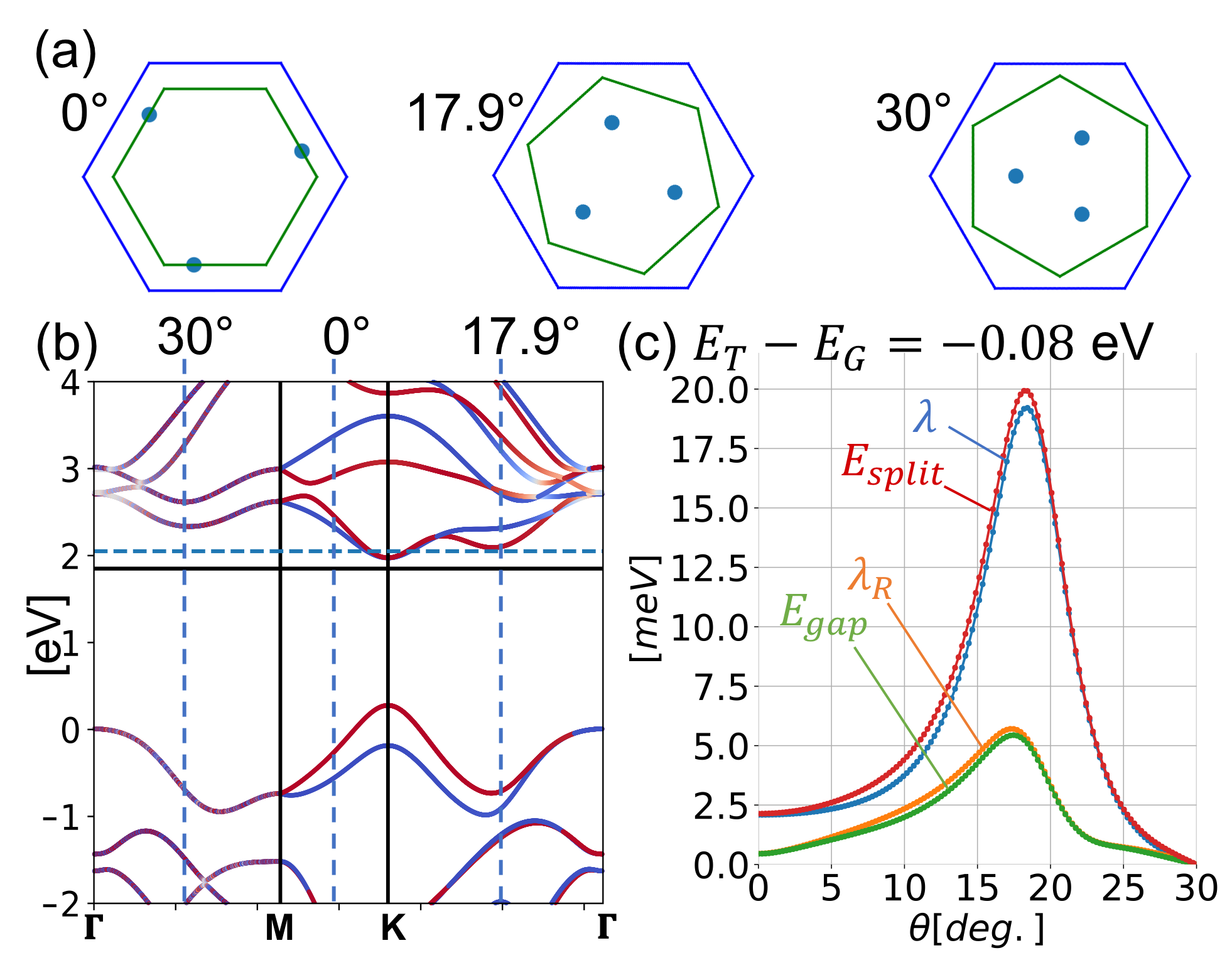 Figure 1
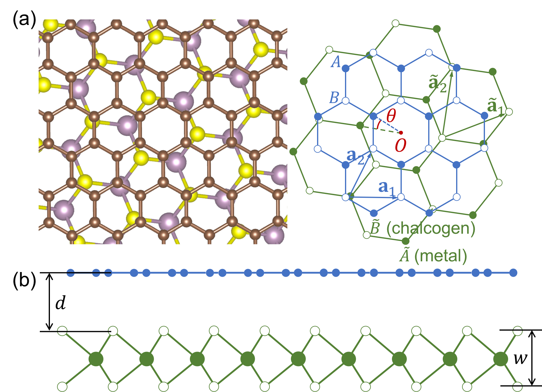 Figure 2
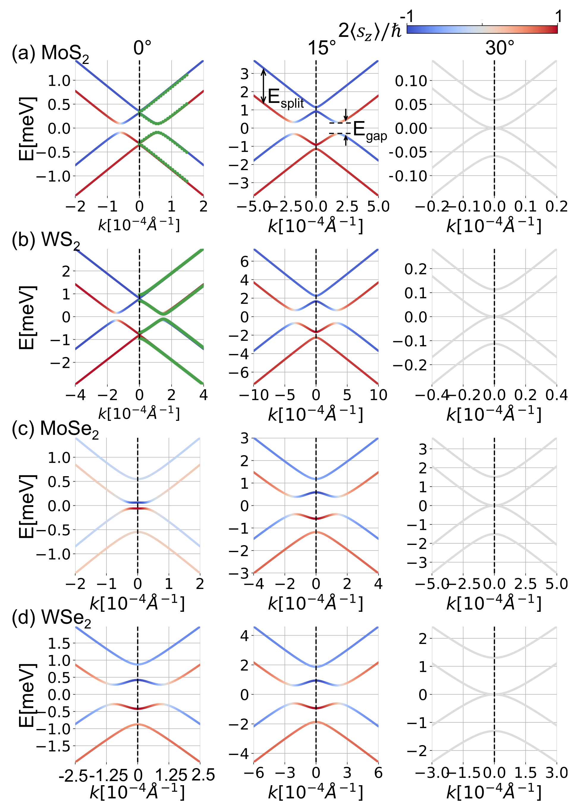 Figure 3
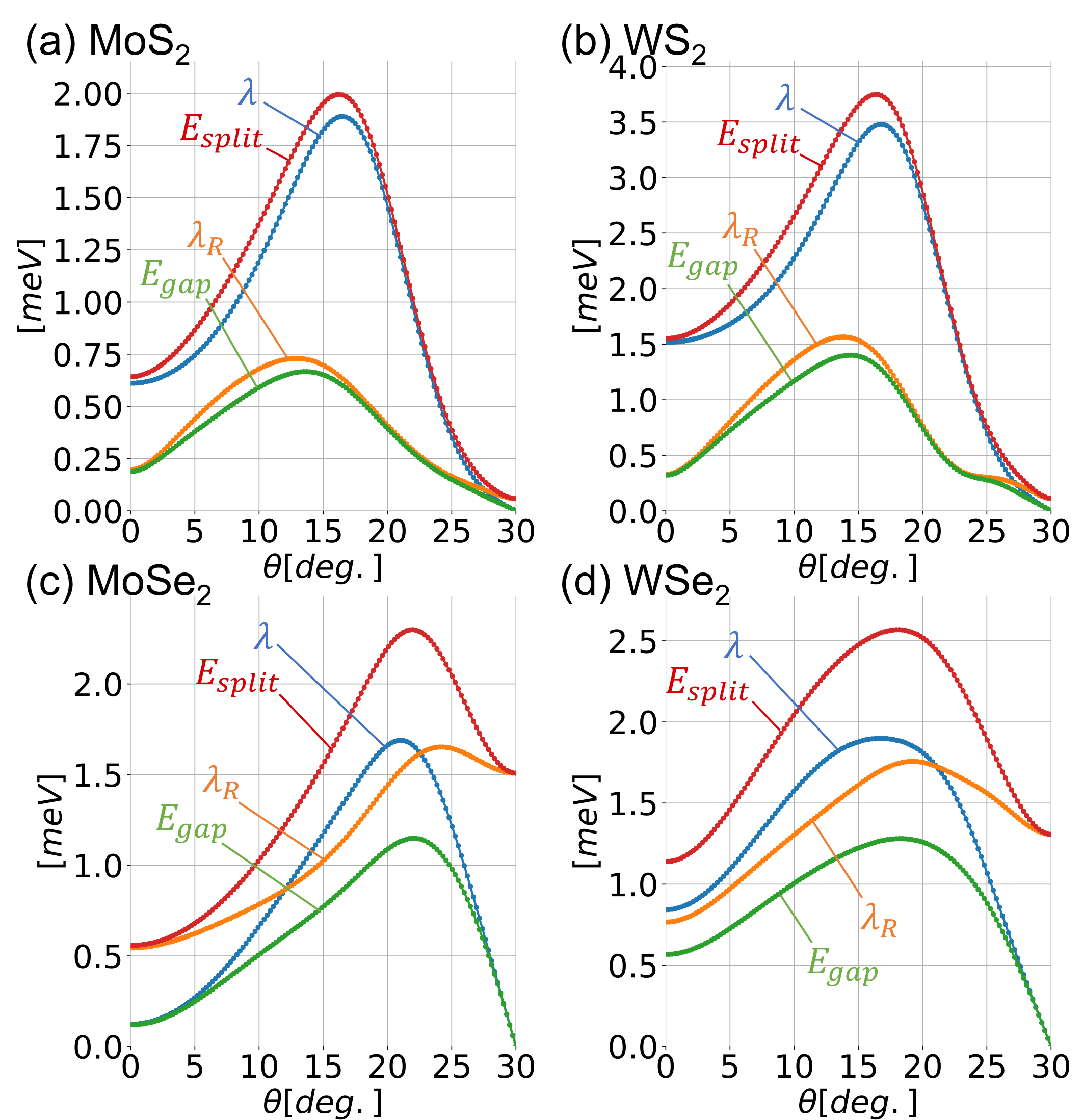 Figure 4
| MoS2 | MoSe2 | WS2 | WSe2 | |
|---|---|---|---|---|
| (Å) | 3.18Fang et al. (2015) | 3.32Fang et al. (2015) | 3.18Fang et al. (2015) | 3.32Fang et al. (2015) |
| (Å) | 3.13Fang et al. (2015) | 3.34Fang et al. (2015) | 3.14Fang et al. (2015) | 3.35Fang et al. (2015) |
| (Å) | 3.37Fang et al. (2015) | 3.41Ma et al. (2011) | 3.41Kaloni et al. (2014) | 3.42Kaloni et al. (2014) |
| (eV) | 0.02Gmitra and Fabian (2015) | 0.6Ma et al. (2011) | 0.12Kaloni et al. (2014) | 1.06Agnoli et al. (2018); Kaloni et al. (2014) |
Peer Reviews
No public reviews on file for this paper yet. If you reviewed it on a platform where reviews are public (OpenReview, ICLR, NeurIPS, ICML), you can paste yours below so the community can read it here.
Videos
No videos yet. Explain this paper in a talk, walkthrough, or lecture? Add one.
Twist-angle dependence of the proximity spin-orbit coupling in graphene on transition-metal dichalcogenides
Yang Li
Department of Physics, Tohoku University.
Mikito Koshino
Department of Physics, Osaka University.
Abstract
We theoretically study the proximity spin-orbit coupling in graphene on transition-metal dichalcogenides monolayer stacked with arbitrary twist angles. We find that the relative rotation greatly enhances the spin splitting of graphene, typically by a few to ten times compared to the non-rotated geometry, and the maximum splitting is achieved around . The induced SOC can be changed from the Zeeman-type to the Rashba-type by rotation. The spin-splitting is also quite sensitive to the gate-induced potential, and it sharply rises when the graphene’s Dirac point is shifted toward the TMDC band. The theoretical method does not need the exact lattice matching and it is applicable to any incommensurate bilayer systems. It is useful for the twist-angle engineering of a variety of van der Waals proximity effects.
††preprint: APS/123-QED
The physical properties of 2D material are generally sensitive to the interference with other materials placed in contact. In recent years, a great deal of experimental and theoretical efforts have been made to explore the proximity-induced phenomena in van der Waals heterostructures consisting of different 2D crystals.Geim and Grigorieva (2013) In particular, it was shown that the negligibly small spin-orbit coupling (SOC) of intrinsic graphene can be significantly enhanced by superimposing on the surface of transition-metal dichalcogenides (TMDC), Avsar et al. (2014); Kaloni et al. (2014); Gmitra and Fabian (2015); Wang et al. (2015a) and it is expected to be useful to realize spintronic manipulation in graphene.
In the studies on the proximity effect on 2D materials, however, the importance of the relative lattice orientation has often been overlooked. The previous theoretical calculations of proximity spin-orbit effects of graphene/TMDC system are limited to the non-rotated geometry. Kaloni et al. (2014); Gmitra and Fabian (2015); Wang et al. (2015a) On the other hand, the sensitive dependence on the relative twist angle was noticed in various 2D hetrostructures, and controlling is expected to be powerful means of manipulating their electronic properties. Carr et al. (2017); Ribeiro-Palau et al. (2018) In graphene on hexagonal BN system, for instance, the moiré interference pattern gives rise to the formation of the secondary Dirac points and the miniband structure. Kindermann et al. (2012); Wallbank et al. (2013); Mucha-Kruczyński et al. (2013); Jung et al. (2014); Moon and Koshino (2014); Dean et al. (2013); Ponomarenko et al. (2013); Hunt et al. (2013); Yu et al. (2014) The twisted bilayer graphene also exhibits the dramatic angle-dependent phenomena, such as the flat band formation Lopes dos Santos et al. (2007); Mele (2010); Trambly de Laissardiere et al. (2010); Shallcross et al. (2010); Morell et al. (2010); Bistritzer and MacDonald (2011); Moon and Koshino (2012); de Laissardiere et al. (2012) and the emergent superconductivity. Cao et al. (2018a, b) For graphene/TMDC hetrostructure, the twist-angle dependent band structure was theoretically simulated for several commensurate angles by the density functional theory (DFT) Wang et al. (2015b); Di Felice et al. (2017); Hou et al. (2017), and it is also experimentally probed. Jin et al. (2015); Pierucci et al. (2016); Du and Yu (2017); Lu et al. (2017) However, the -dependence of spin-orbit coupling induced on graphene remains still unclear. It is generally hard to consider arbitrary twist angles in the DFT calculation, because it requires exact lattice matching to have a finite unit cell.
In this letter, we theoretically study the proximity SOC effect in graphene-TMDC heterostructures with arbitrary twist angles , and reveal the angle dependence of SOC for various different TMDCs. Using the tight-binding model and the perturbational approach, which do not need the commensurate lattice matching, we obtain the effective Hamiltonian of graphene as a continous function of . We find that the relative rotation greatly enhances the spin splitting, typically by a few to ten times compared to the non-rotated geometry , and the maximum splitting is achieved around . We also show that the induced SOC is composed of the Zeeman-like term and the rotated Rashba-like term, and the relative magnitude can be controlled by rotation. Finally, we demonstrate that the spin-splitting is quite sensitive to the relative band energy between graphene and TMDC, and it sharply rises when the graphene’s Dirac point is shifted toward TMDC band by applying the gate voltage. The theoretical method proposed here is applicable to any incommensurate bilayer systems where the DFT calculation cannot be used, and therefore it considerably extends the applicability of the theoretical framework to a wide variety of van der Waals heterostructures.
We consider monolayer graphene placed on the top of a TMDC monolayer. Graphene and TMDC are two dimensional honeycomb lattices with different lattice periods, Å for graphene and for TMDC given in table 1. We define the stacking geometry starting from non-rotated arrangement with parallel bond directions, and then rotating TMDC by the twist angle around the common center of hexagon as in Fig. 1(a). The lattice structure has the (120∘) rotational symmetry with respect to the rotation center. We neglect the degree of freedom of the in-plane parallel translation between TMDC and graphene, since in an incommensurate system it can always be incorporated with the shift of the origin. Koshino (2015)
The lattice vectors of graphene are then given by and , and those of TMDC are by and , where is the rotation matrix. The unit cell area is and for graphene and TMDC, respectively. The reciprocal lattice vectors, , are defined by . We define as the distance between the graphene layer and the top chalcogen layer, and as the distance between top and bottom chalcogen layers. The values of and depend on TMDCs as shown in table 1.
We model graphene by the tight-binding model of carbon orbitals, where the sublattice is labeled as for A and B sites, respectively. For TMDC, we adopt the tight-binding model including three orbitals for a chalcogen atom and five orbitals for a transition metal atom Fang et al. (2015). The orbitals in a TMDC unit cell is labeled by , where and represent top and bottom chalcogen layers. The positions of the orbitals are given by
[TABLE]
where and are integers, and \mbox{\boldmath\tau}_{X} and \mbox{\boldmath\tau}_{\tilde{X}} are the sublattice position inside the unit cell. Specifically, they are expressed as , for graphene, and for the transition metal -orbitals and for the top and bottom charcogen -orbitals, respectively, where and .
The Hamiltonian is spanned by the Bloch bases,
[TABLE]
where are the spin indexes, and are the two-dimensional Bloch wave vectors parallel to the layer, and and are the number of unit cells of TMDC and graphene, respectively, in the total system area .
The total tight-binding Hamiltonian is expressed as where and are the Hamiltonian for the intrinsic graphene monolayer and TMDC monolayer, respectively, and is for the coupling between graphene and TMDC. For , we adopt the hopping parameters based on the first principles calculation Fang et al. (2015) where the spin-orbit coupling is included by on-site term for each atom. The on-site energy of the TMDC atoms relative to the carbon atoms is extracted from the relative energy from the graphene Dirac point to TMDC conduction band edges in the first principles calculationsGmitra and Fabian (2015); Agnoli et al. (2018); Ma et al. (2011, 2011); Kaloni et al. (2014), which are listed in Table 1.
For the interlayer interaction, we assume that the transfer integral from to is expressed as , with the Slater-Koster parameterization Slater and Koster (1954) and the exponential decay in the distance. Here the hopping amplitude and the decay length are determined to fit the first principles calculations. The detailed method is described in the supplementary materials. The coupling between the Bloch state of graphene and that of TMDC is then given by Bistritzer and MacDonald (2011); Koshino (2015)
[TABLE]
Here and are reciprocal lattice vectors of graphene and TMDC, respectively, is the in-plane Fourier transform of the transfer integral defined by
[TABLE]
where z_{\tilde{X}X}=(\mbox{\boldmath\tau}_{\tilde{X}}-\mbox{\boldmath\tau}_{X})\cdot{\bf e}_{z}.
The Hamiltonian of graphene including the TMDC proximity effect can be obtained by the second order perturbation as , where
[TABLE]
Here is the energy of the graphene’s Dirac point, and and are the eigen energy and eigen state of , respectively, with the band index (including the spin degree of freedom) and the Bloch vector . Note that is written as a linear combination of of the same . The summation over in Eq. (5) is taken according to the condition Eq. (3).
The low-energy Hamiltonian is obtained by expanding around the valley center , where is the valley index. Within the linear term, is approximated by , where is the band velocity of graphene, and and are Pauli matrices for the sublattice space . Ando (2009). For the proximity SOC term, we only take the zero-th order . Now that the transfer integral attenuates exponentially and so does its Fourier transform , it suffices to keep only a few ’s in the summation of Eq. (5). For , the dominant contribution comes from three points, , while the effect of other ’s are negligibly small. In this way, the effective proximity potential can be obtained by considering TMDC Bloch states at only three wave points, and the corresponding computing cost is considerably low.
We can show that can be written as,
[TABLE]
where is the Pauli matrix for spin. It is explicitly written in a matrix form,
[TABLE]
where the bases are arranged by order of , , and . The difference in the diagonal elements leads to the spin splitting between spin up and spin down, and the off-diagonal term mixes the different spins. The term with is similar to the Rashba spin-orbit coupling Kane and Mele (2005); Wang et al. (2015a) but here the spin axis can be rotated by an angle on -plane. The energy gap at the charge neutral point is given by . The spin splitting width in large is given by . The effective Hamiltonian is formally equivalent with that of the asymmetric bilayer graphene, McCann (2006); McCann and Koshino (2013) where the spin up and down correspond to layer 1 and 2, respectively, and and to the interlayer coupling and the interlayer asymmetric potential, respectively.
The form of Eq. (6) is forced by the symmetry of the system. The terms in Eq. (6) are generally allowed in the time reversal symmetry and the symmetry. Actually, the term proprotional to (different on-site energies at and sites) is also possible under and Wang et al. (2015a), while it is prohibited by the incommesurability between graphene and TMDC, as explained in Supplementary Material. An additional space symmetry imposes a constraint on . At , the reflection symmetry requires is real. At , the reflection symmetry requires real and also , i.e., the SOC is dominated by the Rashba term. The detailed argument of the symmetry consideration is presented in Supplementary Material.
We numerically calculate for MoS2, WS2, MoSe2 and WSe2. Figure 2 summarizes the results, where , , the central energy gap and the spin splitting are plotted against the twist angle . In Fig. 3, we present the band structures for each system at the rotation angles , and . In the band plots of MoS2 and WS2 at , the dotted green line indicates the first DFT calculations, from which we extract the interlayer hopping parameters. For the DFT calculation, we assume the approximate commensurate lattice structure of which unit cell is comprised of 33 supercell of MoS2 and 44 of graphene, and use Quantum EspressoGiannozzi et al. (2009, 2017) with the generalized gradient approximationPerdew et al. (1996). We can see that the effective model well reproduces the DFT band structure.
For the angle dependence, we find that and are greatly enhanced by rotation, and they take the maximum around . For WS2, in particular, the maximum splitting is about 5 times as large as that of 0∘. At 30*∘*, the parameter vanishes and the is dominated by as expected. There the band structure is formally equivalent to the symmetric AB-stacked bilayer graphene, and the expectation value of spin lies on the -plane.
The enhancement of the spin-splitting near can be understood by considering the second-order process, Eq. (5). The amplitude of is related to the spin splitting of the TMDC bands at points which are hybridized with the graphene’s Dirac point. Figure 4(a) illustrates the positions of the three dominant ’s for , in WS2 with , and . Figure 4(b) presents the band structure of WS2 with the vertical dashed lines indicating the ’s for the three rotation angles. Now the lowest valence band of TMDC makes the greatest contribution to , as it is the closest to the graphene’s Dirac point energy (black horizontal line), leading to a small denominator in Eq. (5). We can see that the point for happens to be very close to the -valley, where the magnitude of the spin splitting much greater than in other angles. This qualitatively explains the sharp rise of and around . Actually, the spin splitting can be even enhanced by shifting the relative energy between graphene and TMDC. Figure 4(c) plots the angle dependence of the spin-splitting of WS2 with eV, where the graphene’s Fermi energy (blue horizontal line) hits the bottom of the Q-valley. Although the Fermi energy is just a little higher than in Fig. 2(b), the maximum spin splitting sharply increases to 20 meV, about 10 times as big as in , because the denominator in Eq. (5) becomes very small. This suggests that tuning of the spin-orbit coupling would be possible using the external gate voltage.
Finally, the graphene under the proximity potential has the non-zero valley Hall conductivity when the Fermi energy lies in the central gap. The Hall conductivity of each valley sector can be calculated using the Berry curvature as
[TABLE]
where is the Berry connection, is the Bloch function (eigenvector of ) of the band , and occ. stands for the occupied valence bands (). As a result, the valley Hall conductivity becomes .
To conclude, we have studied the proximity spin-orbit interaction in graphene-TMDC bilayers stacked with arbitrary twist angles. By using the perturbational approach based on the tight-binding model, we derived the effective Hamiltonian of graphene as a continuous function of the twist angle , and found that the magnitude of SOC is greatly enhanced by the rotation. We also show that the SOC sharply rises when the graphene’s Dirac point is shifted toward TMDC band, by applying the gate voltage. The theoretical method proposed here does not need the exact lattice matching, so that it is applicable to any incommensurate bilayer systems which cannot be treated by the DFT calculation. It would be useful for the twist-angle engineering of a wide variety of van der Waals proximity effects, including ferromagnetism and superconductivty. M. K. acknowledges the financial support of JSPS KAKENHI Grant No. JP17K05496.
The reference list from the paper itself. Each links out to its DOI / PubMed record.
- 1Geim and Grigorieva (2013) A. K. Geim and I. V. Grigorieva, Nature 499 , 419 (2013).
- 2Avsar et al. (2014) A. Avsar, J. Y. Tan, T. Taychatanapat, J. Balakrishnan, G. Koon, Y. Yeo, J. Lahiri, A. Carvalho, A. Rodin, E. O’Farrell, et al. , Nature communications 5 , 4875 (2014).
- 3Kaloni et al. (2014) T. Kaloni, L. Kou, T. Frauenheim, and U. Schwingenschlögl, Applied Physics Letters 105 , 233112 (2014).
- 4Gmitra and Fabian (2015) M. Gmitra and J. Fabian, Physical Review B 92 , 155403 (2015).
- 5Wang et al. (2015 a) Z. Wang, D.-K. Ki, H. Chen, H. Berger, A. H. Mac Donald, and A. F. Morpurgo, Nature communications 6 , 8339 (2015 a).
- 6Carr et al. (2017) S. Carr, D. Massatt, S. Fang, P. Cazeaux, M. Luskin, and E. Kaxiras, Phys. Rev. B 95 , 075420 (2017).
- 7Ribeiro-Palau et al. (2018) R. Ribeiro-Palau, C. Zhang, K. Watanabe, T. Taniguchi, J. Hone, and C. R. Dean, Science 361 , 690 (2018).
- 8Kindermann et al. (2012) M. Kindermann, B. Uchoa, and D. L. Miller, Physical Review B 86 , 115415 (2012).