Branching of Hydraulic Cracks in Gas or Oil Shale with Closed Natural Fractures: How to Master Permeability
Saeed Rahimi-Agham, Viet-Tuan Chau, Huynjin Lee, Hoang Nguyen, Weixin, Li, Satish Karra, Esteban Rougier, Hari Viswanathan, Gowri Srinivasan, Zdenek, P. Bazant

TL;DR
This paper develops a fracture mechanics model explaining how hydraulic cracks in shale can branch laterally along weak layers, significantly enhancing permeability, which is crucial for optimizing gas or oil extraction.
Contribution
It introduces a novel numerical model showing that weak layers with micro-cracking damage enable lateral crack branching during hydraulic fracturing, improving permeability.
Findings
Lateral crack branching occurs along weak layers with increased permeability.
Weak layers with micro-cracking damage facilitate hydraulic crack propagation.
Enhanced transverse Biot coefficient drives lateral fracture development.
Abstract
While the hydraulic fracturing technology, aka fracking (or fraccing, frac), has become highly developed and astonishingly successful, a consistent formulation of the associated fracture mechanics that would not conflict with some observations is still unavailable. It is attempted here. Classical fracture mechanics, as well as the current commercial softwares, predict vertical cracks to propagate without branching from the perforations of the horizontal well casing, which are typically spaced at 10 m or more. However, to explain the gas production rate at the wellhead, the crack spacing would have to be only about 0.1 m, which would increase the overall gas permeability of shale mass about 10,000. This permeability increase has generally been attributed to a preexisting system of orthogonal natural cracks, whose spacing is about 0.1 m. But their average age is about 100 million…
Click any figure to enlarge with its caption.
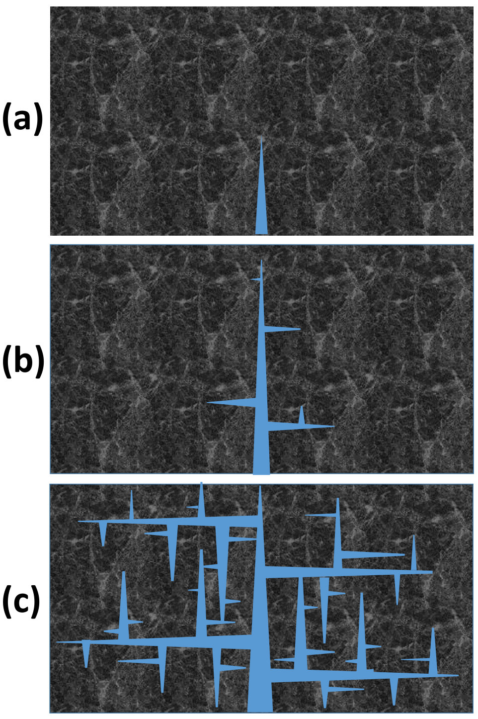 Figure 1
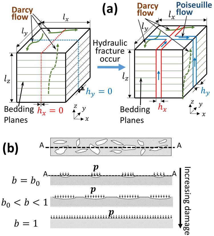 Figure 2
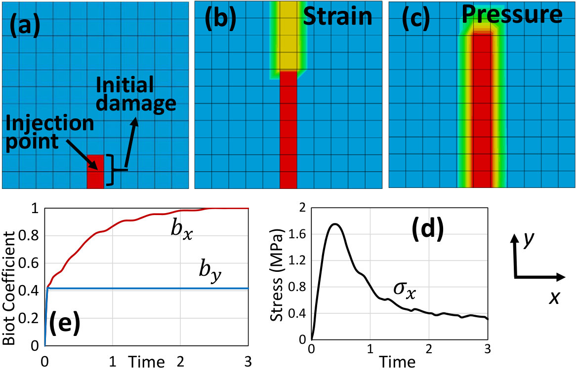 Figure 3
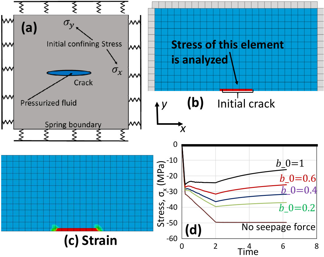 Figure 4
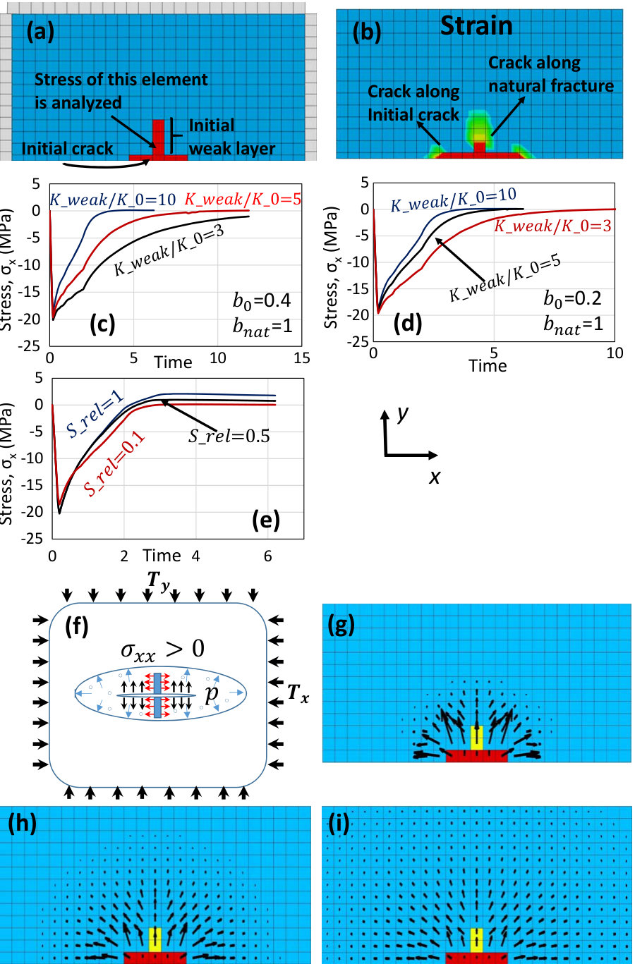 Figure 5
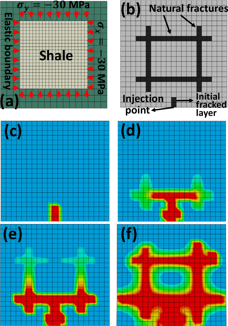 Figure 6
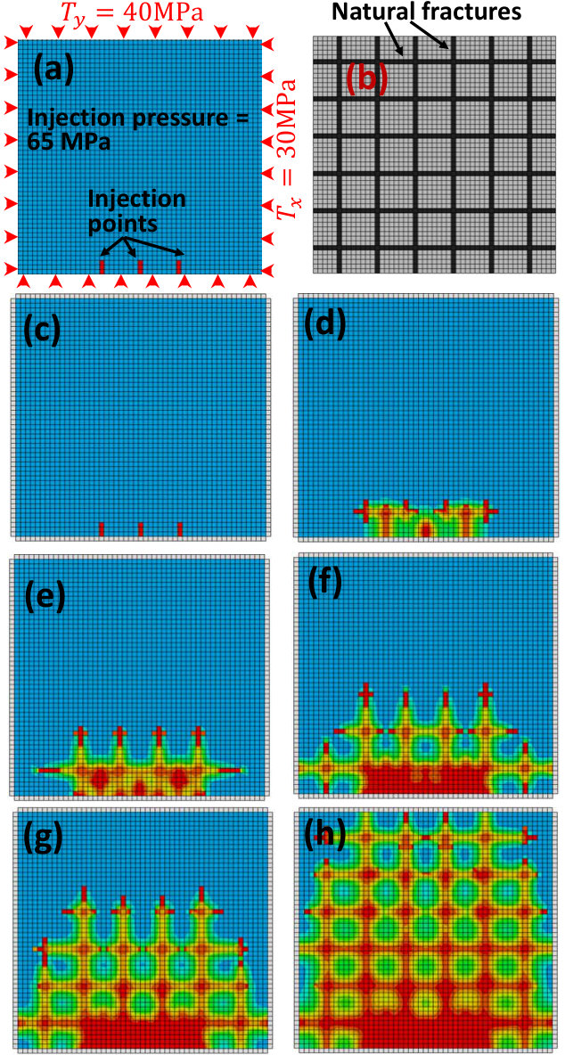 Figure 7
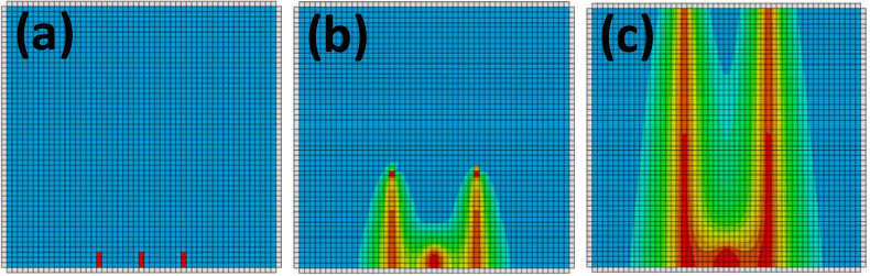 Figure 8
Peer Reviews
No public reviews on file for this paper yet. If you reviewed it on a platform where reviews are public (OpenReview, ICLR, NeurIPS, ICML), you can paste yours below so the community can read it here.
Videos
No videos yet. Explain this paper in a talk, walkthrough, or lecture? Add one.
\templatetype
pnasresearcharticle
Posted on ArXiv, submitted to PNAS
**Branching of Hydraulic Cracks in Gas or Oil Shale with Closed Natural Fractures: How to Master Permeability
**
Saeed Rahimi-Agham, Viet-Tuan Chau, Huynjin Lee, Hoang Nguyen, Weixin Li, Satish Karra, Esteban Rougier, Hari Viswanathan, Gowri Srinivasan, Zdeněk P. Bažant
SPREE Report No. 18-10/076b
Center for Science and Protection of Engineered Environments (SPREE)
Department of Civil and Environmental Engineering
Northwestern University
Evanston, Illinois 60208, USA
November 20, 2018
\leadauthor
Rahimi-Aghdam
\significancestatement
Development of a realistic model of fracking would allow better control. It should make it possible to optimize various parameters such as the history of pumping, its rate or cycles, changes of viscosity, etc. This could lead to an increase of the percentage of gas extraction from the deep shale strata, which currently stands at about 5% and rarely exceeds 15%.
\authorcontributions
Rahimi-Aghdam did the simulations and wrote the first draft, Bažant designed the research and edited the draft. All the other coauthors contributed by discussions. \correspondingauthor2To whom correspondence should be addressed. E-mail: [email protected]
Branching of Hydraulic Cracks in Gas or Oil Shale with
Closed Natural Fractures: How to Master Permeability
Saeed Rahimi-Aghdam
Northwestern University, Department of Civil and Environmental Engineering, 2145 Sheridan road, Evanston, Illinois 60208
Viet-Tuan Chau
Earth and Environmental Sciences Division, Los Alamos National Laboratory, Los Alamos, NM 87545, USA
Huynjin Lee
Northwestern University, Department of Civil and Environmental Engineering, 2145 Sheridan road, Evanston, Illinois 60208
Hoang Nguyen
Northwestern University, Department of Civil and Environmental Engineering, 2145 Sheridan road, Evanston, Illinois 60208
Weixin Li
Northwestern University, Department of Civil and Environmental Engineering, 2145 Sheridan road, Evanston, Illinois 60208
Satish Karra
Earth and Environmental Sciences Division, Los Alamos National Laboratory, Los Alamos, NM 87545, USA
Esteban Rougier
Earth and Environmental Sciences Division, Los Alamos National Laboratory, Los Alamos, NM 87545, USA
Hari Viswanathan
Earth and Environmental Sciences Division, Los Alamos National Laboratory, Los Alamos, NM 87545, USA
Gowri Srinivasan
X Computational Physics Division, Los Alamos National Laboratory, Los Alamos, NM 87545, USA
Zdeněk P. Bažant
McCormick Institute Professor and W.P. Murphy Professor of Civil and Mechanical Engineering and Materials Science, Northwestern University, 2145 Sheridan road, Evanston, Illinois 60208
Abstract
While the hydraulic fracturing technology, aka fracking (or fraccing, frac), has become highly developed and astonishingly successful, a consistent formulation of the associated fracture mechanics that would not conflict with some observations is still unavailable. It is attempted here. Classical fracture mechanics, as well as the current commercial softwares, predict vertical cracks to propagate without branching from the perforations of the horizontal well casing, which are typically spaced at 10 m or more. However, to explain the gas production rate at the wellhead, the crack spacing would have to be only about 0.1 m, which would increase the overall gas permeability of shale mass about 10,000. This permeability increase has generally been attributed to a preexisting system of orthogonal natural cracks, whose spacing is about 0.1 m. But their average age is about 100 million years, and a recent analysis indicated that these cracks must have been completely closed by secondary creep of shale in less than a million years. Here it is considered that the tectonic events that produced the natural cracks in shale must have also created weak layers with nano- or micro-cracking damage. It is numerically demonstrated that a greatly enhanced permeability along the weak layers, with a greatly increased transverse Biot coefficient, must cause the fracking to engender lateral branching and the opening of hydraulic cracks along the weak layers, even if these cracks are initially almost closed. A finite element crack band model, based on recently developed anisotropic spherocylindrical microplane constitutive law, demonstrates these findings.
keywords:
Fracking Poromechanics Biot Coefficient Seepage forces Damage
\dates
This manuscript was compiled on March 9, 2024 www.pnas.org/cgi/doi/10.1073/pnas.XXXXXXXXXX
\dropcap
Significant advances have been made in fracture mechanics of propagation of a single hydraulic crack in elastic rock under tectonic stress (1, 2, 3, 4, 5, 6, 7, 8, 9, 10, 11). They include characterization of the stress singularity at the tip of a water-filled advancing crack, flow of water of controlled viscosity along the crack, with or without proppant grains, and water leak-off into the shale. Interactions of parallel cracks, their stability, closing, and stress-shadow effect, have also been clarified (12, 13, 14, 15). Discrete element models used in most commercial softwares, in which the hydraulic crack was simulated by a band of inter-element separations (16, 17), led to similar results.
These studies, however, predicted no branching of the hydraulic cracks, originally spaced at cca 10 m. This presented a dilemma since branching is the only way to reduce the crack spacing to about 0.1 m, which is necessary to explain the gas production rate. Consequently, it has been universally hypothesized that the preexisting natural cracks, spaced at cca 0.1 m, would somehow increase the overall permeability of the shale mass. A 10,000-fold increase of permeability would be necessary to match the gas production rate. But recent analysis (18, 19) showed that the natural, tectonically produced, cracks, which are on the average about 100 million years old, must have been closed by secondary creep (or viscous flow) of shale under tectonic stress within 10,000 to 1 million years (if not filled earlier by calcite deposit). This invalidated the hypothesis.
It might be objected that water in the cracks could have prevented crack closing. But the open spaces in shear cracks, created (due to shear dilatancy) by a tectonic event, could not have been filled by water immediately. If the water had to seep in from the ground surface, it would take about 10 million years, if from a nearby water-filled rock formation, certainly over a million years. This must have left plenty of time for the creep closing to proceed uninhibited.
A recent paper (20) presented a new model which, by contrast with all the previous studies, took into account: 1) the seepage forces (i.e., the body forces due gradients of pore pressure in Darcy diffusion of water into porous shale), and 2) the variation of effective Biot coefficient for the water pressure on the crack plane, caused by gradually vanishing bridges between the opposite faces of a widening bridged crack (another difference from the previous studies was to abandon the assumption of incompressibility of water in the cracks, since water is about 20-times more compressible than shale). This model (20) did predict extensive lateral crack branching.
Later analysis, however, showed that the branching indicated by the computer program in (20) was, in fact, triggered by the unintended coding of a sudden change of Biot coefficient for transverse water pressure on the crack. This change abruptly increased the water pressure on the solid phase and triggered dynamic response. Such a sudden trigger is probably unrealistic, which represents a vital correction to the preceding study (20) (this correction nevertheless reveals a useful fact, namely that producing shocks in fluid pressure could greatly enhance crack branching).
If the change in Biot coefficient is made gradual, the model from the previous study (20) would predict no crack branching, although the branching must occur to explain the observed gas production rate. This study will show that if the previous model (20) is enhanced by introducing, into the shale mass, significant heterogeneity due to damaged weak layers along preexisting natural cracks, then an extensive and dense crack branching is predicted.
It may be noted that the fracking companies are aware of the necessity of branched cracks running along preexisting natural fractures. Fig. 1 shows a picture similar to what is found on the websites of some companies. However, this awareness seems to be merely intuitive and empirical. The existing commercial softwares, as well as fracture mechanics studies, predict no branching. So an intersecting system of open natural fractures is assumed to either exist a priori or to develop according to some empirical criteria with no basis in mechanics, supported by some recent experiments indicating the possibility of branching (21, 22, 23, 24). A physics-based model for branching, which is our goal, seems lacking.
Fluid flow in porous solid, without or with cracking damage
Two types of flow play a role in hydraulic fracturing: 1) The flow along the hydraulically created cracks, typically a few millimeters wide, and 2) the flow through nano-scale pores and micro- or nano-cracks in shale with preexisting damage. The latter is negligible after continuous hydraulic cracks form, but here it is found to be crucially important for crack initiation and branching. The volume flow, , of water through the pores and nano- or micro-cracks of isotropic material may be approximately calculated from the Darcy law: \mbox{\boldmathq}=-(K/\mu)\mbox{\boldmath\nabla}\psi where = permeability, dynamic viscosity and phase potential calculated as, Here pore pressure, pressure gradient due to gravity, and depth from a datum. However, the permeability in the direction normal to the bedding planes , i.e., in vertical direction ) is much lower than permeability along these planes (horizontal). Therefore, the three-dimensional Darcy law is, in general, anisotropic. In Cartesian coordinates (, the resulting volume flux vector \mbox{\boldmathq}=(q_{x},q_{y},q_{z}) may be written as
[TABLE]
where is the vector of gradient operator; and is the permeability matrix, which is diagonal if (and only if) the cartesian axes are chosen to be parallel and normal to the bedding planes.
Although the natural (or preexisting) cracks in shale strata at 3 km depth must have been closed by hundred million years of creep, the damage bands along these cracks, which always accompany propagation of fracture process zone, certainly remain (in fact, based on the known surface energy of shale, it can be shown that even empty pores and cracks cca 15 nm in size, at depth 3 km, cannot close, and this is confirmed by the known size of pores containing shale gas). Permeability along these bands is surely much higher than it is in the intact shale (but pores 15 nm contribute nothing globally).
To prevent the formation of horizontal cracks, the pumping pressure is assumed not to exceed the overburden pressure, which is about 75 MPa. The hydraulic fracturing is considered to produce a system of mutually orthogonal vertical cracks, normal to the directions of the minimum and maximum principal tectonic stresses. The flow of the second type, along the hydraulically created cracks, may be assumed to follow the Reynolds equations of the classical lubrication theory, which are based on the Poiseuille law for viscous flow. Thus the horizontal and vertical flow vector components in directions along with the cracks may be calculated as
[TABLE]
where ,…; = opening widths of vertical cracks normal to axes and that are positioned into the bedding plane.
An effective way to simulate the hydraulic cracks numerically is the crack band model (25, 26, 27), in which cracking deformation is considered meared over the band (or element) width. The widths of cracks normal to and are:
[TABLE]
(Fig.2) where = damage parts of normal strains due to smeared cracking normal to and directions; = crack band widths, assumed equal to the minimum possible spacing of adjacent parallel hydraulic cracks ( must be treated as a material property, related to fracture energy of shale; here are not changed but if they were the postpeak would have to be adjusted to preserve ). Furthermore,
[TABLE]
where = transversely isotropic elastic compliance tensor of shale (for unloading); are the stress and strain tensors in the rock, calculated from a constitutive model for smeared cracking damage (with a localization limiter (25)), for which the spherocylindrical microplane constitutive model (28) has been used. The coordinates are Cartesian, (). Note that, the same as in (20), water is considered as compressible. It is, in fact, about 20-times more compressible than concrete, and the water pressure during fracking can be high (up to 70 MPa).
Equilibrium in two-phase solid and Biot coefficient
The shale may be modeled as a two-phase medium with water-saturated pores, for which the classical Biot-type relations for the equilibrium of the phases apply. For undamaged shale, they read:
[TABLE]
where pore pressure, Biot coefficient of undamaged shale; = total stress tensor; = stress tensor in the solid phase, and = Kronecker delta. As a special case, where = volumetric total stress, and = volumetric stress in the solid phase.
While typically , the Biot coefficient of shales can vary between and . Test results (29, 30, 31, 32, 33, 34) show that it increases with the cracking damage and depends on the load direction. This requires generalizing the Biot coefficient as a tensor, (35). The following, tensorially consistent, empirical relation, which appears to match test data, is proposed:
[TABLE]
Here refers to undamaged material, = empirical parameter, is the inelastic damage strain tensor, and = natural porosity of shale. For the Biot coefficient in the direction of unit vector , this equation gives (but ), where = inelastic relative volume expansion, and = inelastic normal strain component in direction of vector .
For the special case of micro- or nano-cracking normal to direction only, one has and (but ). This equation can be interpreted graphically as seen in Fig. 2b, which shows section A-A of a band of preexisting, mostly aligned, microcracks and the compressive stresses applied by the pore fluid onto the microcrack faces, resisted by tensile stresses in the ligaments of the solid between the microcrack tips.
The viscous drag of water flowing through a soil imposes a seepage force on the soil in the direction of flow. The seepage forces are body forces defined as
[TABLE]
They are applied on the porous solid and must be balanced by stresses in the solid. Seepage in an upward direction reduces the effective stress within the soil. When the water pressure at a point in the soil is equal to the total vertical stress at that point, the effective stress is zero and the soil has no frictional resistance to deformation (36, 37). They have long been considered in geotechnical engineering to assess the risk of sand liquefaction in cofferdams (38, 39) or under dams. However (except for (20)) they have been ignored in previous studies of hydraulic fracturing, although they do play a crucial role in crack branching. A poromechanical finite element (FE) code for a two-phase solid automatically takes the seepage forces into account in the form of nodal forces.
Two-phase finite element (FE) simulations for a single damage band
To clarify the role of nano- or micro-cracking, consider first a horizontal two-dimensional (2D) square block of shale of dimensions 1.1 m 1.1 m, supported at the sides by springs approximately equivalent to an infinite medium, as shown in Fig. 3a. Water is injected at the center of south side at the constant rate of 2 m3/s. The anisotropic spherocylindrical microplane model, with the default parameters of shale given in (28), is used as the constitutive model; and = 2.1 m. The initial Biot coefficient is . The tectonic stresses are MPa, MPa.
Consider that there is a single preexisting band of nano- or micro-cracks predominantly aligned with axis , represented by the two red elements in Fig. 3a (which is what remains after a crack was closed by up to a million years of secondary creep, or viscous flow). These cracks cause the vertical permeability in these two elements to increase cca 1000-times compared to undamaged shale, while the Biot coefficient increases up to 1 and the initial strength decreases to 10% of intact shale.
Figs. 3b,c show how damage and pressure propagate after water injection. For this case, the crack band with high water pressure is seen to propagate straight forward, without branching. Now look at stress variation. Fig. 3d shows the stress evolution within in the solid part of the first element above the initial damaged elements. Obviously, the damage during post-peak softening is captured in a stable manner. Finally, consider how the Biot coefficient and permeability vary in one cracked element (the first above the initial damaged elements). Fig. 3e contrasts the evolution of Biot coefficient in the transverse direction with its constancy in the forward direction, which agrees with experimental observations.
Do they seepage forces suffice to induce crack branching?
It is well known in classical fracture mechanics that pressurizing a crack cannot produce tension along the crack faces, and thus cannot initiate lateral crack branching (branching is possible only at the tip of a crack propagating at nearly the Raleigh wave speed). In a preceding study (20), it was surmised, under various simplifications, that the seepage forces (Eq. 7) would suffice for produce tension along the crack face and thus initiate lateral crack branching. Let us examine it more rigorously. Consider again a horizontal 2D square domain 2.5 m 2.5 m, containing one line crack (Fig. 4a). By virtue of symmetry, only a half-domain is simulated (Fig. 4b). The water pressure in the line crack is gradually ramped up to reach the maximum of 50 MPa. Water diffusion from the pressurized crack into the shale is simulated via Darcy law. First we neglect the increase of Biot coefficient due to damage (. Fig. 4c shows that the damage, as well as the crack, propagates only in the direct extension of the initial line crack, i.e, there is no branching. Fig. 4d shows the evolution of stress in the solid part, , along the crack face. The results show that the Biot coefficient can have a major effect and cannot be ignored.
Lateral crack branching would happen if the stress in the solid phase became positive (tensile) and attained the tensile strength of shale. The results show that this cannot happen, regardless of the tectonic stress value (even if vanishing). Nevertheless, the seepage forces reduce the magnitude of compressive stress along the crack face significantly.
We must thus conclude (as an update of (18)) that the seepage forces alone do not suffice to explain and model lateral branching of hydraulic cracks. So, what other phenomena could explain the lateral branching? Not surprisingly, the explanation is the natural (preexisting) fractures even though they must have been completely closed due to millions of years of secondary creep, or flow. We demonstrate it next.
Hydraulic crack branching in two-phase porous solid with closed natural fractures
In Fig. 5a we now consider the same 2D domain of two-phase porous solid as before, except that now there are two natural weak layers (or preexisting damage bands) in both and directions. The crack is uniformly pressurized and water diffuses out. The transverse Biot coefficient within the weak layers that represent the closed natural fractures is because the weak layer (or natural fracture) may consist of separate original crack faces in contact (uncemented by limestone deposit), while in the intact shale the -values increase according to Eq. (6) from the initial value (Fig. 5d) or (Fig. 5d).
Fig. 5b reveals that the hydraulic crack tends to propagate simultaneously along the initial crack and along the weak layer. This confirms that branching can occur if transverse weak layers exist. Further, consider the normal stress parallel to the crack in one element of the weak layer. If this stress attains the tensile strength, a lateral crack branch can initiate and shale branching can happen. Fig. 5b shows the spreading of high and lower transverse strains along both weak layers for the case of Biot coefficient , with permeability along the weak band 5-times bigger than for intact shale.
The computed effect of ratio on the evolution in the first element of the weak layer above initial crack is plotted in Fig. 5c,d for the initial Biot coefficients, = 0.4 and 0.2. As water diffuses into the shale, the stress in the weak layer increases from negative to tensile values until it finally reaches the tensile strength of the weak layer. Evidently, a greater difference in Biot coefficient between the weak layer and the shale facilitates, and speeds up the crack branching.
Finally, to clarify the effect of the transverse tensile strength of the weak layer, three relative strength values are considered in Fig. 5e (here is the damaged-to-intact strength ratio of shale). As seen, a smaller leads to smaller stress, but generally, the effect of is almost negligible. Hence, whether or not the natural cracks are cemented by limestone is almost irrelevant.
It is instructive to see the evolution of the seepage force vectors acting on the mesh nodes, as portrayed in Fig. 5. Fig. 5f shows schematically the seepage forces acting on an ellipse around the crack. Fig. 5g-i illustrates the evolution of seepage forces. Their orientations make it intuitively clear that they must produce in the porous solid a biaxial tension.
From all these observations, it transpires that a major stimulus for crack branching is the difference in the Biot coefficient and in the permeability between the weak layers and the intact shale, as well as the shale mass heterogeneity due to the alternation of weak layers and intact porous solid.
It is worth mentioning that the expansion of solid due to the effect of Biot coefficient has been thought to prevent any tension parallel to the crack face, and thus cause the closing of any lateral crack. The preceding results show that this skeptical view does not extend to a heterogeneous shale mass containing weak layers alternating with intact shale.
To demonstrate the present theory on a larger scale, consider a bigger horizontal section of shale, a square domain 5 m 5 m, containing a uniform orthogonal system of closed natural fractures with aligned preexisting weak layers (Fig. 7). To be more realistic, unequal tectonic stresses are considered in and directions; 30MPa and =40MPa.
Water is injected at three points at the bottom of the figure. Figs. 7c–7h show the evolution of water pressure. Water flow and damage strain are seen to follow the path of weak layers. Extensive branching occurs. Obviously, this branching can create closely spaced hydraulic cracks and thus increase the overall permeability of shale stratum by orders of magnitude, compared to non-branching cracks in intact shale.
It has also been checked that omitting the natural fractures leads to no branching. This is evident from the pressure propagation pattern in Fig. 8. This figure also documents the localization instability of parallel crack system (12) (aka the stress shadow effect), which causes that the crack emanating from the middle injection point cannot grow long (the long simultaneous growth of both remaining cracks is made possible by the proximity of the boundaries).
Conclusions
The natural fractures have a major effect on hydraulic fracturing and are crucial for its success (although they are currently neglected by the commercial fracking softwares). 2. 2.
Even though the natural fractures must have been closed by millions of years of creep, or sealed by mineral deposits, a weak layer of nano- and micro-cracks along these fractures must be expected to facilitate water diffusion. 3. 3.
Poromechanics with Biot coefficient depending on the damage of the solid phase must be used in the analysis of fracking. 4. 4.
Increase of the Biot coefficient in the transverse direction, caused by oriented cracking damage inflicted by fracking, is essential to achieve crack branching. 5. 5.
The typical spacing between natural fractures is roughly 0.1 m. This value matches the spacing of hydraulic cracks that is necessary to explain the typical gas production rate at the wellhead. 6. 6.
The widespread opinion that preexisting natural fractures somehow explain why the overall permeability of shale mass, inferred from the gas production rate, appears to be about 10,000 times higher than what is measured on shale cores in the laboratory, has been basically correct. But these fractures are completely closed, do not convey any gas and their role is indirect. 7. 7.
a) No porosity no branching. b) No seepage forces no branching. c) No weak layers no branching. d) Constant Biot coefficient no branching. (Note: consequently, branching in granite is impossible)
\acknow
The work at Northwestern was funded by LANL grant to Northwestern University. The last author thanks Emmanuel Detournay, University of Minnesota, for valuable discussions and a stimulating challenge that provoked part of this study.
\showacknow
The reference list from the paper itself. Each links out to its DOI / PubMed record.
- 1(1) Abe H, Keer L, Mura T (1976) Growth rate of a penny-shaped crack in hydraulic fracturing of rocks, 2. Journal of Geophysical Research 81(35):6292–6298.
- 2(2) Beckwith R, , et al. (2010) Hydraulic fracturing: the fuss, the facts, the future. Journal of Petroleum Technology 62(12):34–40.
- 3(3) Adachi JI, Detournay E (2008) Plane strain propagation of a hydraulic fracture in a permeable rock. Engineering Fracture Mechanics 75(16):4666–4694.
- 4(4) Advani S, Torok J, Lee J, Choudhry S (1987) Explicit time-dependent solutions and numerical evaluations for penny-shaped hydraulic fracture models. Journal of Geophysical Research: Solid Earth 92(B 8):8049–8055.
- 5(5) Carbonell RS (1997) Ph.D. thesis (University of Minnesota, Minneapolis, Minnesota).
- 6(6) Detournay E, Garagash D (2003) The near-tip region of a fluid-driven fracture propagating in a permeable elastic solid. Journal of Fluid Mechanics 494:1–32.
- 7(7) Adachi JI (2002) Ph.D. thesis (University of Minnesota, Minneapolis, Minnesota).
- 8(8) Valko P, Economides MJ (1995) Hydraulic fracture mechanics . (Wiley New York) Vol. 28.