Dispersion enhanced tunability of laser-frequency response to its cavity-length change
Savannah L. Cuozzo, Eugeniy E. Mikhailov

TL;DR
This paper demonstrates how modifying intracavity dispersion in a four-wave mixing regime can controllably enhance or suppress the laser's frequency response to cavity length changes, enabling applications in sensitive measurements and precision metrology.
Contribution
It introduces a method to controllably tune the laser frequency response to cavity length changes by adjusting intracavity dispersion in Rb-based four-wave mixing.
Findings
Response increased by at least 2.7 times
Response can be drastically reduced
Potential applications in sensitive measurements and metrology
Abstract
We report on the controllable response of the lasing frequency to the cavity round-trip path change. This is achieved by modifying the dispersion of the intracavity medium in the four-wave mixing regime in Rb. We can either increase the response by at least a factor of or drastically reduce it. The former regime is useful for sensitive measurements tracking the cavity round trip length and the latter regime is useful for precision metrology.
Click any figure to enlarge with its caption.
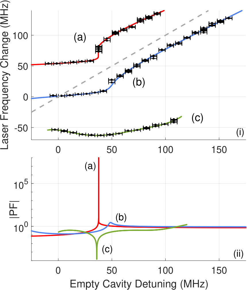 Figure 1
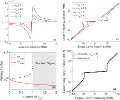 Figure 2
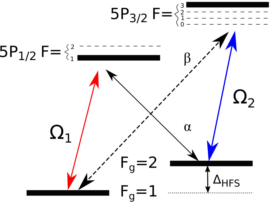 Figure 3
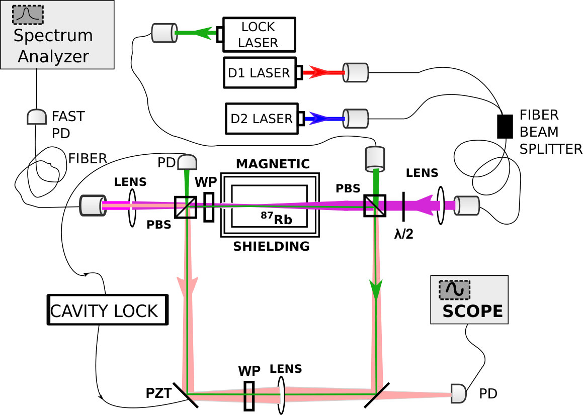 Figure 4
Peer Reviews
No public reviews on file for this paper yet. If you reviewed it on a platform where reviews are public (OpenReview, ICLR, NeurIPS, ICML), you can paste yours below so the community can read it here.
Videos
No videos yet. Explain this paper in a talk, walkthrough, or lecture? Add one.
Dispersion enhanced tunability of laser-frequency response to its
cavity-length change
Savannah L. Cuozzo
Eugeniy E. Mikhailov
Department of Physics, College of William Mary, Williamsburg, Virginia 23187, USA
Abstract
We report on the controllable response of the lasing frequency to the cavity round-trip path change. This is achieved by modifying the dispersion of the intracavity medium in the four-wave mixing regime in Rb. We can either increase the response by at least a factor of or drastically reduce it. The former regime is useful for sensitive measurements tracking the cavity round trip length and the latter regime is useful for precision metrology.
pacs:
42.50.Lc, 42.50.Nn
We control the response of the lasing frequency to the laser cavity length change on demand — allowing for either dramatic enhancement or suppression. The resonant frequency link to the cavity round trip path is the foundation for optical precision measurements such as displacement tracking, temperature sensing, optical rotation tracking Chow et al. (1985), gravitational wave sensing Abbott and et al. (2016), and refractive index change sensing Jiyang Li (2017). In other applications, the laser provides a stable frequency reference, such as precision interferometry Martynov and et al (2016), optical atomic clocks Ludlow et al. (2015), and distance ranging Jang and Kim (2017), where the response of the lasing frequency to the cavity path length change should be reduced. Our findings allow for improved laser assisted precision metrology and potentially make lasers less bulky and immune to the environmental changes in real world applications.
The addition of a dispersive medium to a cavity modifies its frequency response Shahriar et al. (2007) to the geometrical path change () according to
[TABLE]
where is the original resonant frequency, is the total optical round-trip path of the cavity, is the length of the dispersive element, is the length of the empty (non-dispersive) part of the cavity, is the refractive index, and is the generalized refractive group index given by
[TABLE]
We define the pulling factor (PF) as the ratio of dispersive to empty (non-dispersive, ) cavity response for the same path change
[TABLE]
The PF is the figure of merit for the enhancement of the cavity response relative to canonical lasers or passive cavities operating in the weak dispersion regime with .
We tune the PF in the range from -0.3 to at least (see Fig. 1), by tailoring the refractive index of our lasing medium. This is the first demonstration of high and tunable PF in the laser. We can also push our system response further and reach the bifurcating regime.
Due to Kramers-Kronig relationship the negative dispersion is accompanied by local absorption, so it is not surprising that so far the regime was experimentally demonstrated only in passive, non-lasing cavities Pati et al. (2007); Smith et al. (2016, 2018) with PF. For active cavities, Yablon et al. Yablon et al. (2016) inferred a PF via analysis of the lasing linewidth. The increased stability regime (PF) was demonstrated in lasing Kutzke et al. (2017) cavities with the smallest being PF Yablon et al. (2017). Superradiant (“bad-cavity”) lasers, where an atomic gain line is much narrower than a cavity linewidth, exhibit ultra low PF Bohnet et al. (2012); Norcia et al. (2018). Our empty cavity linewidth is about 13 MHz which is larger than any atomic decoherence time, so we operate in the “bad-cavity” regime. However, unlike previously reported work in Bohnet et al. (2012); Norcia et al. (2018), we can also achieve higher than one PF.
Similar to Zhou et al. (2016), we present a simple model of the transmission or amplification spectral line where the index of refraction has the dependence:
[TABLE]
where is the resonance strength, is the detuning from the medium resonance frequency (), and is the resonance width, since for a vapor filled cavity. For transmission or gain resonances with , the minimum and maximum PF are
[TABLE]
where
[TABLE]
is the bifurcating threshold resonance strength.
The analysis of the dispersion (Eq. 4) and its influence on the resonant frequency of the cavity and PF is shown in Fig. 2. As expected, the amplification line has positive dispersion on resonance (see Fig. 2a). Positive dispersion is associated with a large and positive group index, which results in weak dependence (low pulling factor) of the lasing frequency on the cavity path change (empty cavity detuning), as shown in Fig. 2b. Away from resonance, the dispersion is negative leading to high PFs, as shown in Fig. 2b. The stronger the amplification () the smaller the PFmin is at the center of the resonance, as shown in Fig. 2b. Consequently, the PFmax continuously grows and reaches infinity at where the resonant frequency bifurcates (see Fig. 2b).
To track dependence of the cavity resonant frequency on the cavity path length, we solve:
[TABLE]
where is the fixed mode number and is the speed of light in vacuum. In experiment, it is easier to track the empty cavity detuning (i.e. resonance frequency change, ), which is directly linked to the cavity path change via Eq. 1 with . The resulting dependencies are shown in Fig. 2c.
If the negative dispersion is strong enough, the group index could be negative. This would lead to negative PF and to negative dependence of the lasing frequency on the cavity detuning (see line corresponding in Fig. 2c). This behavior is nonphysical, since it corresponds to a bifurcation Zhou et al. (2016): multiple lasing frequencies for the same cavity detuning. Consequently, the laser would ‘jump’ to avoid negative PF region and preserve the monotonic behavior, as shown in Fig. 2d and experimentally in Fig. 1(i)a.
The most important conclusion from the amplifying line analysis is that high pulling (response enhancement) regions exist slightly away from the gain resonance. The precursor of such regime is a reduced PF region in close vicinity to the resonance. The off resonance behavior was overlooked in the literature, while it actually provides the road to high PF. Away from the amplification resonance, the system still has enough gain to sustain lasing, and yet it still has large negative dispersion (see Fig. 2a). As detuning from the resonance increases, the dispersion becomes negligible, PF approaches unity (see Fig. 2c and experimental data in Fig. 1 a and b), amplification drops and eventually lasing ceases.
To experimentally demonstrate the modified lasing response to the cavity path change, one needs a narrow gain line to achieve the highest positive dispersion. We utilized the N-level pumping scheme depicted in Fig. 3. The theory and preliminary experimental study of this arrangement are covered in references Kutzke et al. (2017); Mikhailov et al. (2014); Phillips et al. (2013). The strong pumping field creates a transmission line for the field due to electromagnetically induced transparency. However, the field alone is not enough to create the amplification. To create the gain for the field, we apply another strong repumping field (). There is also gain for the field, which completes the four-wave mixing arrangement of fields , , , and . But the cavity is tuned to sustain lasing only for .
Our lasing cavity is similar to the one used in Kutzke et al. (2017). The ring cavity is made of two polarizing beam splitters (PBS) and two flat mirrors. The round trip path of the cavity is 80 cm. A 22 mm long Pyrex cylindrical cell with anti-reflection coatings on its windows is placed between the two PBSs and filled with isotopically pure 87Rb. The cell is encased in a 3-layer magnetic shield and its temperature is set to 100 degrees C. The optical stability of the cavity is increased by adding a 30 cm focal length lens placed between the two mirrors. This lens also places the cavity’s mode waist inside the 87Rb cell.
To produce experimental data sets (a) and (b) shown in the Fig. 1, two pump lasers are tuned near D1 (795 nm) and D2 (780 nm) corresponding to and fields in Fig. 3. The pump fields are coupled to a fiber beam splitter and amplified by a solid state tapered amplifier to powers ranging between 100 mW for set (a) and 170 mW for set (b), and then injected into a ring cavity through a polarizing beam splitter (PBS). The D1 laser is tuned 700 MHz below the Fg=1 F=1 transition, and D2 is set to 500 MHz below the F F=3 87Rb transition, as seen in Fig. 3. They provide amplification for fields and , which are generated orthogonal to pump fields polarization. Only the field resonantly circulates in the cavity, since the pumps exit the cavity via the second PBS and is kept off-resonance with the cavity.
Since the D1 pump laser is fixed, the beatnote of the pump () and the lasing field () with its frequency close to 87Rb hyperfine splitting ( GHz) is related to the frequency of the ring cavity laser and allows us to monitor the dispersive laser frequency change (). We control the cavity length by locking it to an auxiliary laser (called the lock laser) with a wavelength of 795 nm that is far detuned from any atomic resonances and senses a “would be empty” (dispersion-free) cavity detuning (). This lock laser beam counter propagates relative the pump beams and the lasing field to avoid contaminating the detectors monitoring the ring cavity lasing. Two wave plates (WP) are placed inside the cavity. One is to spoil polarization of the lock field and allow it to circulate in the cavity. The other rotates the lasing field polarization by a small amount. This allows it to exit the cavity and mix in with the pump field on the fast photodetector.
The maximum response has the lower bound of PF at the 90% confidence level for the data set (a), shown in Fig. 1. The upper bound for PFmax is infinity since the data set belongs to the bifurcating regime. However, one can smoothly approach this limit by carefully controlling the cavity detuning as our analysis shows in Fig. 1(ii)a. The PFmin range is to for this data set.
We can avoid bifurcation by increasing the pumps’ powers (i.e., we increase via power broadening), as shown in the data set (b) of Fig. 1. This data demonstrates PFmax in the range (2.3 to 3.2). Also, the range of detuning with PF is wider. To estimate confidence bounds, we use the modified smoothed bootstrap method Efron and Tibshirani (1994).
We are able to make our dispersive laser insensitive to its path change, as shown in data set (c) of Fig. 1. We tune tune the D1 laser to 400 MHz above the Fg=1 F=1 transition, and keep D2 at 500 MHz below the F F=3 87Rb transition, while maintaining combined pump power at 95 mW. Assuming a smooth dependence on the empty cavity detuning, the PF at the bottom of the U-like curve is exactly zero, as the laser frequency decreases and then increases, while the cavity path (the auxiliary laser detuning) changes monotonically. Our model governed by Eq. 4 cannot explain the arching behavior, since it does not account for the dependence of the dispersion on the lasing power. However, a more complete model which solves density matrix equations of the N-level scheme predicted such a possibility Kutzke et al. (2017).
There is an ongoing debate whether or not the modified cavity response leads to improved sensitivity (signal to noise ratio) of path-change sensitive detectors. However, laser-based sensors in certain applications might benefit either from enhanced PF (for example gyroscopes Shahriar et al. (2007)) or reduced PF, since sensitivity, i.e. the ratio of the response to the lasing linewidth (uncertainty), scales as 1/PF Kuppens et al. (1994); Bohnet et al. (2012); Henry (1982). The tunability and versatility of our system allows to probe either case.
In conclusion, we achieved about increase of the laser response to the cavity-path length change relative to canonical lasers. We also can significantly reduce the response, making our laser vibration insensitive. These findings broadly impact the fields of laser sensing and metrology, including laser ranging, laser gyroscopes, vibrometers, and laser frequency standards.
EEM and SLC are thankful to the support of Virginia Space Grant Consortium provided by grants 17-225-100527-010 and NNX15AI20H. We would like to thank M. Simons, O. Wolfe, and D. Kutzke for assembling the earlier prototype of our laser. We also thank S. Rochester and D. Budker for their earlier work on N-level theoretical model.
The reference list from the paper itself. Each links out to its DOI / PubMed record.
- 1Chow et al. (1985) W. W. Chow, J. Gea-Banacloche, L. M. Pedrotti, V. E. Sanders, W. Schleich, and M. O. Scully, Rev. Mod. Phys. 57 , 61 (1985).
- 2Abbott and et al. (2016) B. P. Abbott and et al. (LIGO Scientific Collaboration and Virgo Collaboration), Phys. Rev. Lett. 116 , 061102 (2016) . · doi ↗
- 3Jiyang Li (2017) Y. X. N. Jiyang Li, Haisha Niu, Optical Engineering 56 , 050901 (2017) . · doi ↗
- 4Martynov and et al (2016) D. Martynov and et al , Phys. Rev. D 93 , 112004 (2016) . · doi ↗
- 5Ludlow et al. (2015) A. D. Ludlow, M. M. Boyd, J. Ye, E. Peik, and P. O. Schmidt, Rev. Mod. Phys. 87 , 637 (2015) . · doi ↗
- 6Jang and Kim (2017) Y.-S. Jang and S.-W. Kim, Int. J. Precis. Eng. Manuf. 18 , 1881 (2017) . · doi ↗
- 7Shahriar et al. (2007) M. S. Shahriar, G. S. Pati, R. Tripathi, V. Gopal, M. Messall, and K. Salit, Phys. Rev. A 75 , 053807 (2007) . · doi ↗
- 8Pati et al. (2007) G. S. Pati, M. Salit, K. Salit, and M. S. Shahriar, Phys. Rev. Lett. 99 , 133601 (2007) . · doi ↗