Electrostatic deflector studies using small prototypes
K. Grigoryev, F. Rathmann, A. Stahl, H. Str\"oher

TL;DR
This paper investigates small-scale electrostatic deflector prototypes to evaluate materials and electric field performance, aiding the development of deflectors for particle storage rings used in electric dipole moment experiments.
Contribution
It introduces scaled-down prototypes for electrostatic deflectors, enabling material and electric field studies at reduced sizes for particle physics applications.
Findings
Material performance varies at small scales
Electric fields comparable to larger prototypes achieved
Insights into design optimization for deflectors
Abstract
The search for electric dipole moments of particles in storage rings requires the development of dedicated deflector elements with electrostatic fields. In these rings, electric deflectors shall be used as bending elements for the charged particles. This paper presents studies on scaled-down prototypes, a few cm in size, to investigate different deflector materials at similar electric fields but much smaller distances than real size prototypes.
Click any figure to enlarge with its caption.
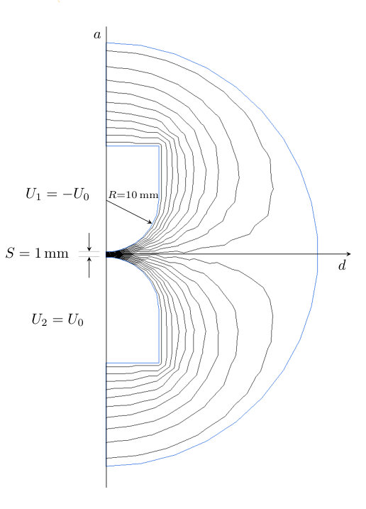 Figure 1
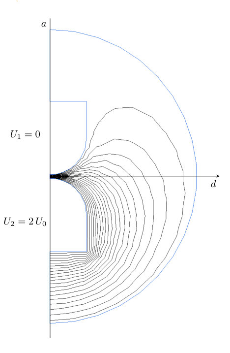 Figure 1
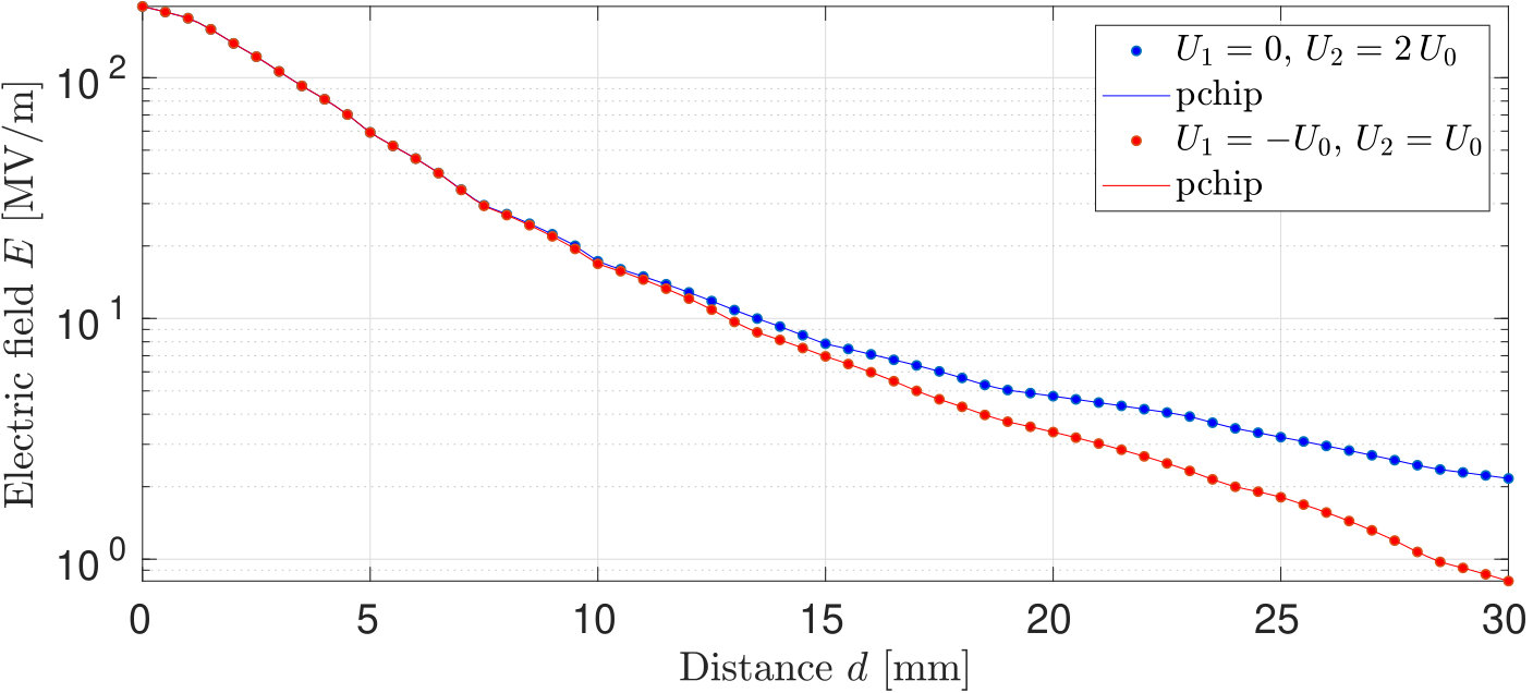 Figure 1
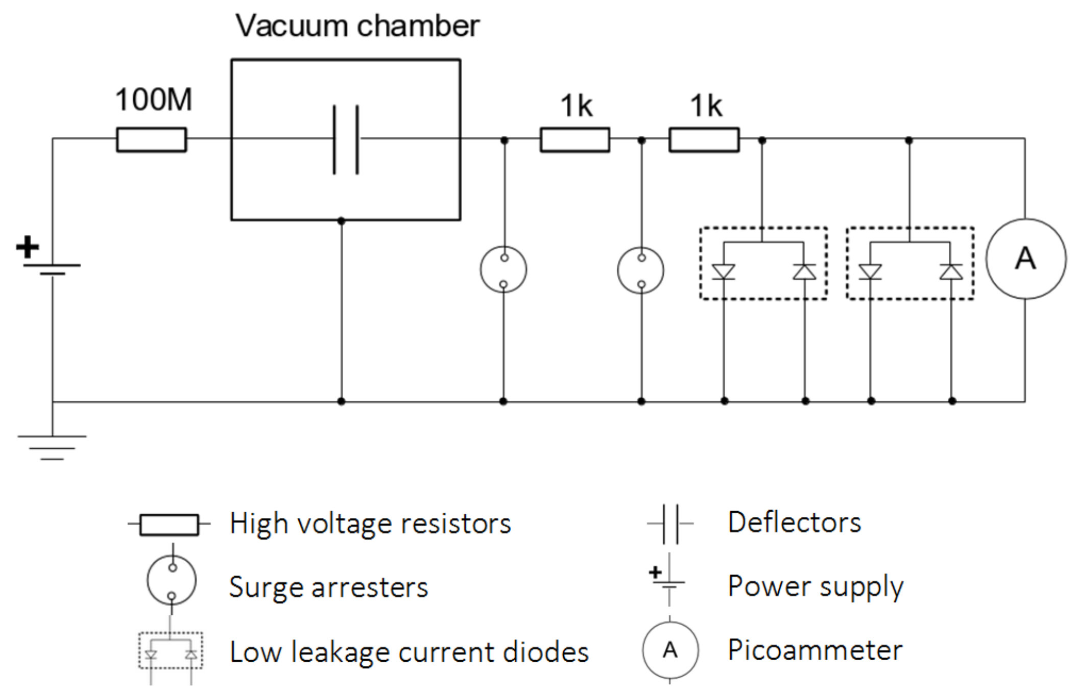 Figure 2
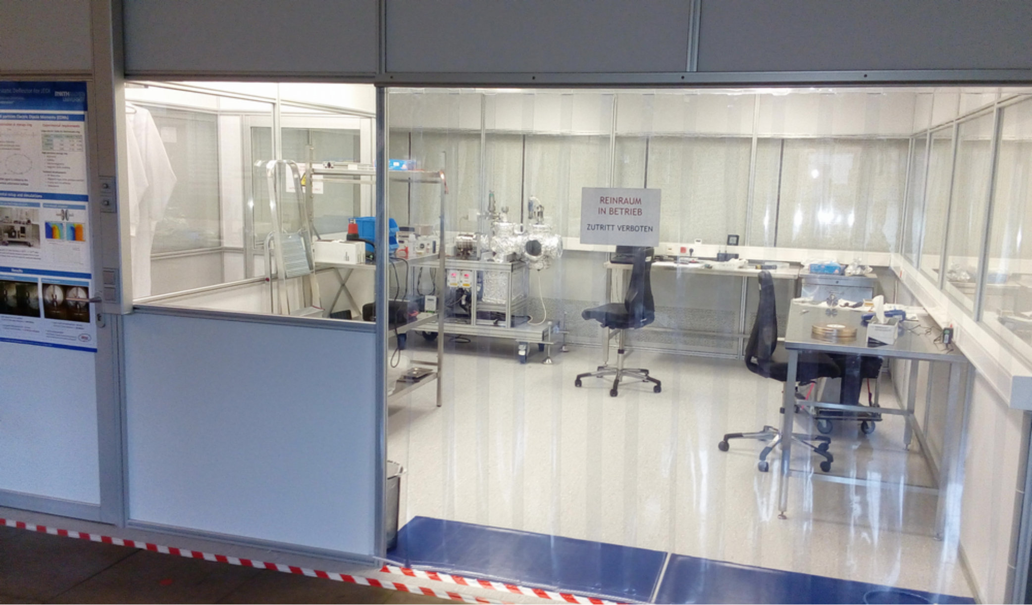 Figure 3
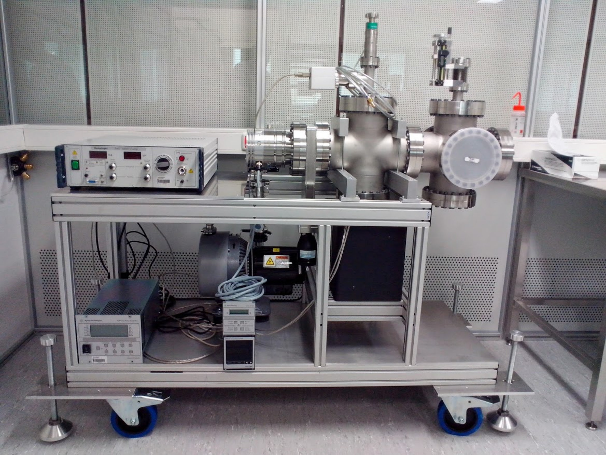 Figure 4
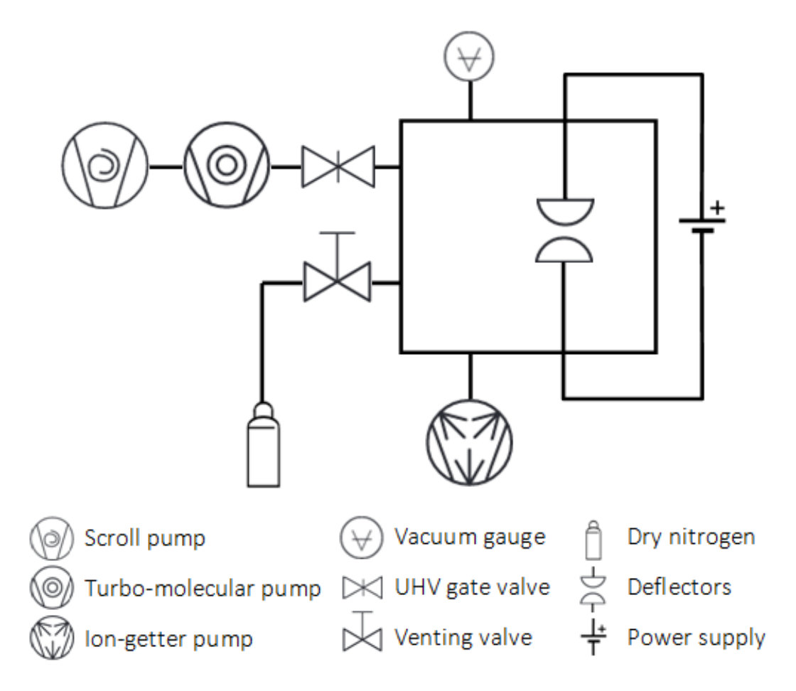 Figure 4
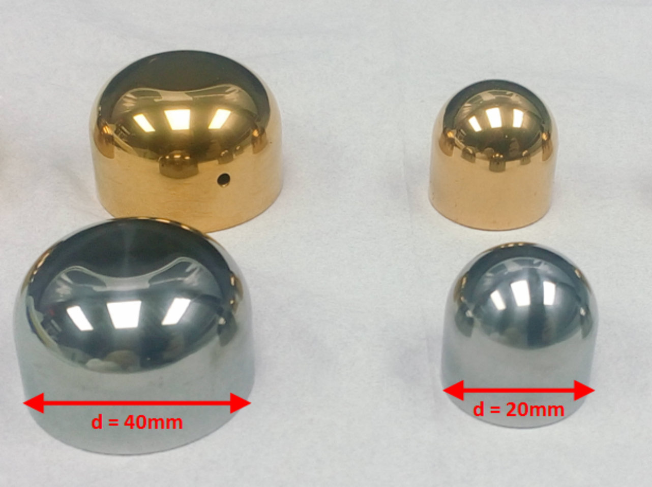 Figure 5
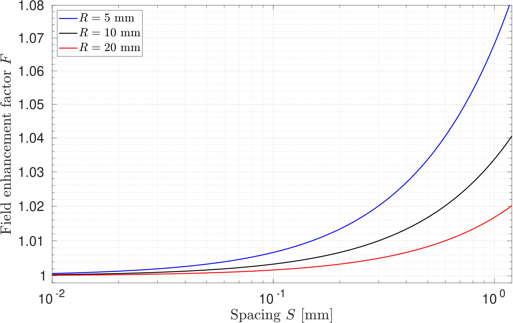 Figure 6
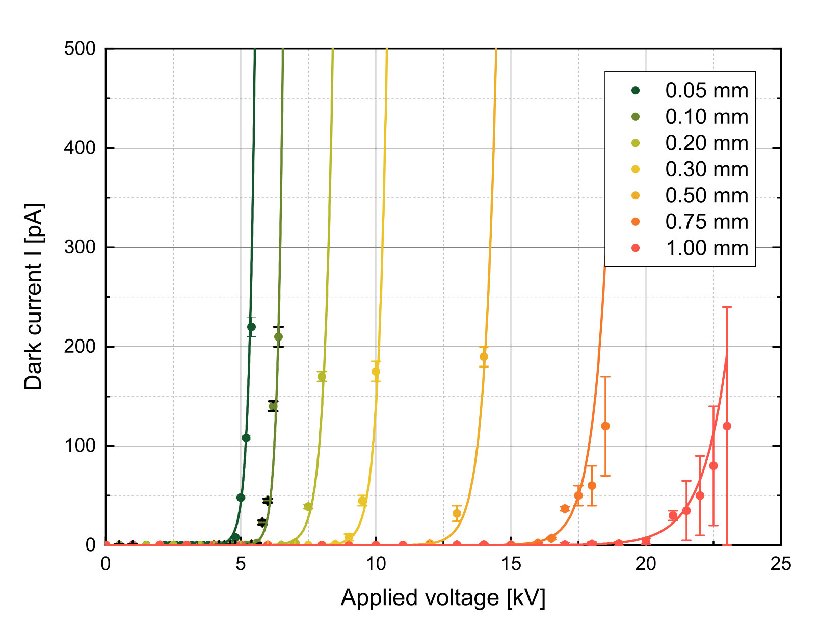 Figure 7
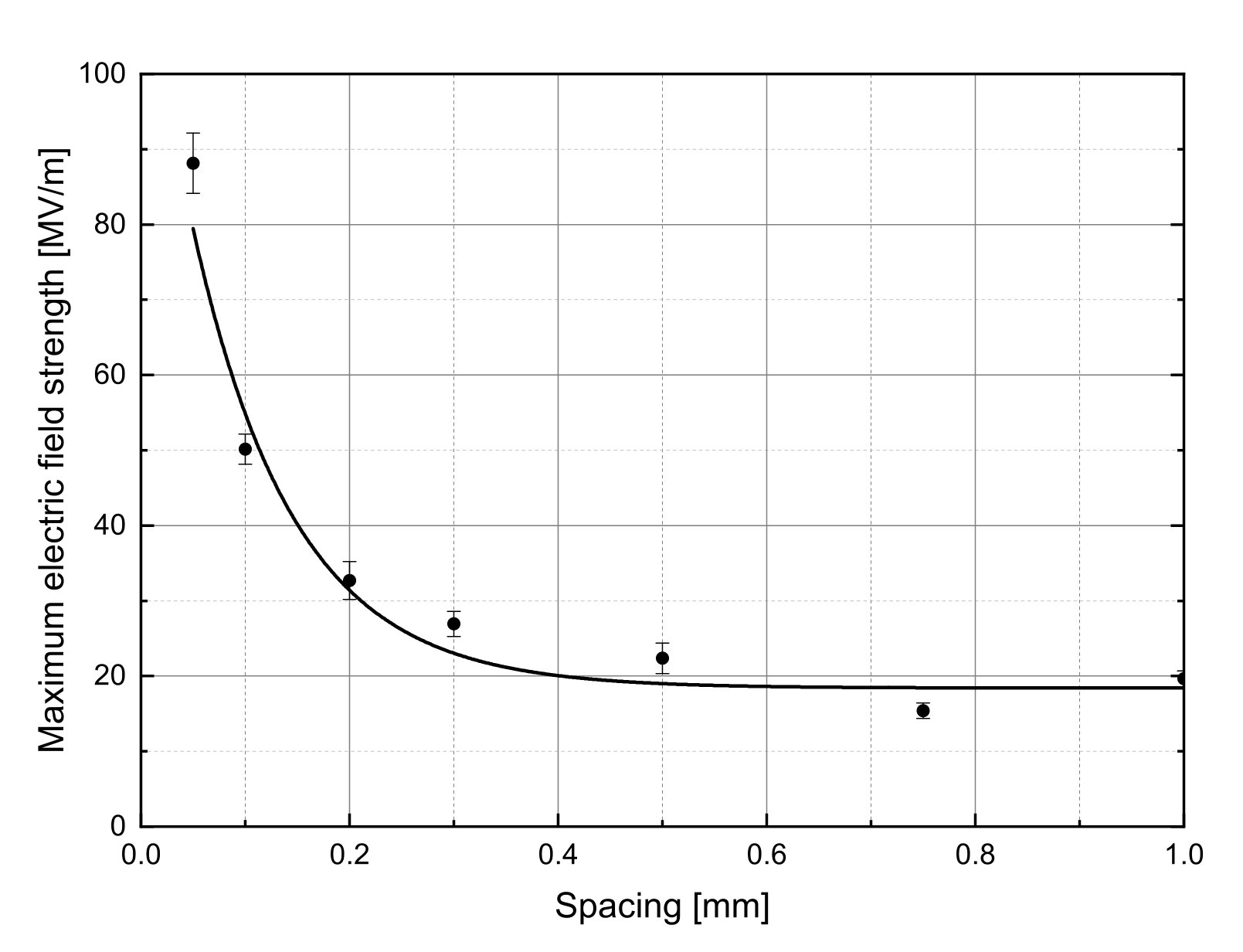 Figure 8
Peer Reviews
No public reviews on file for this paper yet. If you reviewed it on a platform where reviews are public (OpenReview, ICLR, NeurIPS, ICML), you can paste yours below so the community can read it here.
Videos
No videos yet. Explain this paper in a talk, walkthrough, or lecture? Add one.
Electrostatic deflector studies using small-scale prototype electrodes
K. Grigoryev
Institute for Nuclear Physics, Forschungszentrum Jülich, 52425, Jülich, Germany
F. Rathmann
Institute for Nuclear Physics, Forschungszentrum Jülich, 52425, Jülich, Germany
A. Stahl
III Physics Institute B, RWTH Aachen University, 52074, Aachen, Germany
H. Ströher
Institute for Nuclear Physics, Forschungszentrum Jülich, 52425, Jülich, Germany
Abstract
The search for electric dipole moments of particles in storage rings requires the development of dedicated deflector elements with electrostatic fields. The JEDI prototype-ring design consist of more than 50 electric deflectors of length with spacing between the plates with electric field gradients of . This paper presents studies of scaled-down uncoated prototype electrodes of in diameter made from stainless steel. The electric field at distances from down to increased from 15 to . In future investigations we will also study different materials and coatings at similar distance between the electrodes. Preparations are underway to study also large deflector elements.
I Introduction
The JEDI collaboration111Jülich Electric Dipole moment Investigations, http://collaborations.fz-juelich.de/ikp/jedi is searching for permanent electric dipole moments (EDM) of charged particles, such as protons Anastassopoulos et al. (2016) and deuterons Rat (2011). One of the technical challenges is the development of electric bending elements that provide high electric fields. A purely electrostatic EDM ring of radius, for instance, requires electric fields of about Rathmann et al. (2014). The present limit for the electric field of bending elements at accelerators is below Reiser (2008). The electrostatic separators at CESR222Cornell Electron-positron Storage Ring, https://www.classe.cornell.edu/public/lab-info/cesr.html Wel (1999) and Fermilab333Fermi National Accelerator Laboratory, http://www.fnal.gov Tevatron Lebedev and Shiltsev (2014); Shiltsev et al. (2005), and the CERN septa Bor (2003) are routinely operated at smaller electric fields.
In order to study different electrode materials and coatings, the investigations described here made use of scaled-down prototypes and a dedicated UHV test stand installed inside a clean room at RWTH Aachen University. The operation in the laboratory with respect to radiation protection was simplified, because the applied voltages were always below . Nevertheless, by scaling down the applied voltage and by reducing at the same time the spacing between the electrodes, large electric fields could be obtained.
In Sec. II, the experimental setup is described. General considerations of the deflector development are given in Sec. II.1. The electrical scheme using a high-voltage power supply is discussed in Sec. II.2, and the set up of the vacuum system inside a clean room is described in Sec. II.3. The electrodes are presented in Sec. III, and the measurements in Sec. IV. The results are summarized in Sec. V.
II Experimental setup
II.1 Small-scale prototype electrodes
Initial investigations about the shape of electrostatic deflectors were based on existing elements used at the Fermilab Tevatron Prokofiev (2005). The plates of the Tevatron electrostatic separators were designed to provide a field of at distances of 60\text{,}\mathrm{mm}$$ with a length of about . The transverse profile of the Tevatron separators represents a Rogowski profile Trinh (1980). For a specific electrode configuration (i.e., plate separation and height) the surface contour of the electrodes is designed to follow the equipotential lines. Such a profile ensures a high homogeneity of the electric field in the flat region between the deflector plates, and, according to Refs. Rogowski (1923, 1926), a discharge will occur outside of that region.
In order to simplify the mechanical production of prototype elements for the test setup at RWTH Aachen University, all elements were manufactured with round corners rather than with Rogowski profiles. The smallest elements consist of half-spheres with a radius of 10\text{,}\mathrm{mm}$$. Small test samples also served to minimize weight which eliminated the need for a sophisticated support structure.
II.2 Electrical scheme
Numerical simulations of the electric field , performed with the QuickField FEA software444QuickField simulation software, Tera Analysis Ltd, https://quickfield.com, showed that for our studies there is essentially no difference between using the same but opposite potentials between the electrodes or having one of the electrodes powered with twice the voltage , while the other one is grounded (see Fig. 1).
The option with one grounded electrode (see Fig. 1(b)) is more attractive, because the measurements can then be performed with a single high-voltage power supply. In addition, common ground for every device minimizes the measurement noise and makes the dark current detection with a picoammeter555Keithley picoammeter 6485, https://www.tektronix.com more reliable.
The electrical circuit, shown in Fig. 2, consists of two discharge protection elements. The resistor serves to limit the current to ground during HV breakdown. The gas discharge boxes666EPCOS AG, type EPCOS EC90X and EC600X, https://tdk-electronics.tdk.com and the low-leakage diodes777Diodes Incorporated, https://www.diodes.com, type BAV199 protect the picoammeter from high currents during a discharge.
To ensure safe operation, the high-precision high-voltage power supply888Heinzinger PNC 30000, https://www.heinzinger.com/products/high-voltage/universal-high-voltage-power-supplies was equipped with a rapid discharge circuit. A fast discharging capacitor within the power supply reduces the voltage to less than 1% of the applied value in less than . The measured voltage ripple of the power supply was below the specified value of at and was stabilized to better than 0.05% over a time interval of .
II.3 Clean room and vacuum system
To perform the test measurements, a class ISO7999A class ISO7 clean room allows inside of air, a maximum of of size 0.1\text{,}\mathrm{\SIUnitSymbolMicro m}, and not more than $352\,000\text{\,}\mathrm{p}\mathrm{a}\mathrm{r}\mathrm{t}\mathrm{i}\mathrm{c}\mathrm{l}\mathrm{e}\mathrm{s}$ of size $>$0.5\text{\,}\mathrm{\SIUnitSymbolMicro m}. clean room was installed in the experimental hall at RWTH Aachen University with a gateway and a strip curtain for rolling the test apparatus (see Fig. 3). The clean area inside was sufficiently large to place a few tables besides the test stand for the prototypes.
A dust-free vacuum system was designed and built using UHV components, mounted on a movable support for easy access and flexibility during the tests measurement (see Fig. 4(a)). An oil-free turbo-molecular pump101010Agilent TwisTorr 304, https://www.agilent.com with pumping speed and air cooling, backed by a dry scroll pump111111Agilent TriScroll 300, https://www.agilent.com with pumping speed allowed us to reach good vacuum conditions within a few minutes. Simultaneous heating of the chamber to the maximum operating temperature of the turbo-pump () removed water from the stainless-steel walls of the vacuum chamber and brought the pressure down to about .
A ion-getter pump121212Agilent Vaclon Plus 300, https://www.agilent.com, installed directly on the vacuum chamber, equipped with its own heater, was used to activate the ion-getter pump at the same time when the vacuum chamber was baked out. After activation of the ion-getter pump, the vacuum chamber was isolated from the scroll and turbo-molecular pumps using a UHV gate-valve131313Vacom 5GVM-160CF-MV-S, copper sealed ultra-high vacuum hand gate-valve, https://www.vacom.de (see Fig. 4(b)), and the pressure reached about . During the tests the scroll and turbo-molecular pumps were turned off to minimize vibrations. The pressure in the vacuum chamber, measured directly by the ion-getter pump, was typically of the order of .
III Test electrodes
The electrodes for the tests were made of stainless steel in two different sizes. The small ones are half-spheres of radius 10\text{,}\mathrm{mm}$$. The large electrodes additionally possess a flat central region of diameter. Based on the experience reported in Furuta et al. (2005); Mamun et al. (2015), for further investigations a set of stainless-steel samples prepared in the same way was coated by TiN (see Fig. 5). The results of the measurements using stainless steel and aluminum coated with TiN will be described in a forthcoming publication.
The test electrodes were produced and mechanically polished in the RWTH Aachen workshop. The average roughness of the surface was smaller than with a maximum nonuniformity of . Prior to installation into the vacuum chamber, all parts were cleaned in an ultrasonic propanol bath.
For precise positioning, each measurement started by mechanically setting the distance between the electrodes to zero. This was accomplished by applying a small voltage and observation of a large current at the picoammeter when the electrodes touched each other. From there, one of the electrodes was moved to the measurement position using a manual UHV-compatible linear drive141414Compact linear drive CLSM38-50-H-DLA from UHV Design, http://www.uhvdesign.com with positioning accuracy.
The electric field between the two half-spherical electrodes can be written as Russell (1927)
[TABLE]
where denotes the so-called field enhancement factor, the voltage, and the spacing between the electrodes. The field enhancement factor can be calculated for known shapes. For half-spherical electrodes with radius of curvature Dean (1913),
[TABLE]
where denotes the spacing between the two spheres, so that the distance between the centers of the half-spheres is given by
[TABLE]
At the employed distances between and , the field enhancement factor changes only by about 3% (see Fig. 6).
IV Dark current measurements
For the measurements the experimental setup was transferred to the COSY hall at Forschungszentrum Jülich. The first high-voltage tests were performed with well-polished stainless-steel half-sphere electrodes over a wide range of distances ranging from 30\text{,}\mathrm{m}\mathrm{m} to $0.05\text{\,}\mathrm{m}\mathrm{m}$ (see Fig. [7](#S4.F7)). Being limited by the $30\text{\,}\mathrm{kV}$ power supply, the discharges mainly happened in the test conditions with small gaps between the electrodes. No discharge was observed at a distance $S=$10\text{\,}\mathrm{m}\mathrm{m} with an applied voltage of which leads to 4.1\text{,}\mathrm{MV}\text{,}{\mathrm{m}}^{-1}$$. Discharges at larger distances can only be observed when higher voltages are applied which requires a new experimental setup.
For completeness, tests were also carried out by replacing one of the half-sphere electrodes with the larger stainless-steel electrodes with flat surface (see Fig. 5). In that case, the measured electric field behaved in a similar way and reached values which likely correspond to vacuum breakdown conditions Werner (2004); Meek and Craggs (1978).
The measured minimal dark currents were compatible with zero to a tens of a picoampere (see Fig. 7). The maximum values of the electric field , shown in Fig. 8 and calculated using Eq. (1) and from Eq. (2), are taken at the measurement points when the dark current was still compatible with zero within errors. The measurements showed that with half-sphere electrodes of radius at distances of less than a millimeter, electric fields above the required values of 17\text{,}\mathrm{MV}\text{,}{\mathrm{m}}^{-1}$$ could be reached.
The maximum electric fields obtained at a distance 0.05\text{,}\mathrm{mm}, however, are still an order of amplitude smaller than achieved elsewhereDescoeudres *et al.* ([2009](#bib.bib33)) at much smaller distances of $S=$0.02\text{\,}\mathrm{mm}. It should be noticed that with respect to the development of electrostatic deflector elements for the future EDM ring, the region of interest ranges from a few cm to about distance, which can be studied only with large deflectors and much higher applied voltages.
V Summary
Mechanically polished stainless-steel electrodes at distances less than a millimeter demonstrate that electric fields close to the breakdown limit in ultra-high vacuum can be reached. The maximum electric fields obtained in the measurements using scaled-down electrodes look promising. They are clearly above the required values for an electrostatic deflector of for a future EDM ring of radius. The improvement of the HV breakdown capability using different electrodes materials and coatings as well as gas conditioning will be further investigated in the future.
We will now move on to measurements with real-size deflector elements of a length 1020\text{,}\mathrm{mm} at distances of $S\approx$20\text{\,}\mathrm{-}120\text{,}\mathrm{mm}$$ between the plates. A suitable experimental infrastructure with two power supplies is presently set up at IKP of Forschungszentrum Jülich.
Acknowledgements.
This work has been performed in the framework of the JEDI collaboration, and is financially supported by an ERC Advanced-Grant (srEDM # 694390) of the European Union.
The reference list from the paper itself. Each links out to its DOI / PubMed record.
- 1Note (1) Jülich Electric Dipole moment Investigations, http://collaborations.fz-juelich.de/ikp/jedi.
- 2Anastassopoulos et al. (2016) V. Anastassopoulos, S. Andrianov, R. Baartman, S. Baessler, M. Bai, J. Benante, M. Berz, M. Blaskiewicz, T. Bowcock, K. Brown, B. Casey, M. Conte, J. D. Crnkovic, N. D’Imperio, G. Fanourakis, A. Fedotov, P. Fierlinger, W. Fischer, M. O. Gaisser, Y. Giomataris, M. Grosse-Perdekamp, G. Guidoboni, S. Hacıömeroğlu, G. Hoffstaetter, H. Huang, M. Incagli, A. Ivanov, D. Kawall, Y. I. Kim, B. King, I. A. Koop, D. M. Lazarus, V. Lebedev, M. J. Lee, S. Lee, Y. H. Lee, A. · doi ↗
- 3Rat (2011) 8th International Conference on Nuclear Physics at Storage Rings (STORI 11), Po S STORI 11 (2011) 029 (2011). · doi ↗
- 4Rathmann et al. (2014) F. Rathmann, A. Saleev, and N. N. Nikolaev, Physics of Particles and Nuclei 45 , 229 (2014) . · doi ↗
- 5Reiser (2008) M. Reiser, Theory and Design of Charged Particle Beams , 2nd ed. (Wiley Series in Beam Physics and Accelerator Technology, Wiley, 2008).
- 6Note (2) Cornell Electron-positron Storage Ring, , https://www.classe.cornell.edu/public/lab-info/cesr.html.
- 7Wel (1999) 1999 Particle Accelerator Conference (PAC’99): New York, New York, March 29-April 2, 1999 (1999).
- 8Note (3) Fermi National Accelerator Laboratory, http://www.fnal.gov.