Propagation of surface plasmons on plasmonic Bragg gratings
A. J. Chaves, N. M. R. Peres

TL;DR
This paper uses coupled-mode theory to analyze how surface plasmon polaritons interact with finite plasmonic Bragg gratings on metal-dielectric or graphene-covered interfaces, revealing stop-bands and transmission properties.
Contribution
It provides analytical solutions for SPP scattering on finite gratings, including reflectance, transmittance, and Fabry-Pérot oscillations, extending understanding of plasmonic bandgap phenomena.
Findings
Presence of complete back-scattering in stop-bands
Fabry-Pérot oscillations outside stop-bands
Analytical expressions in electrostatic limit
Abstract
We use coupled-mode theory to describe the scattering of a surface-plasmon polariton (SPP) from a square wave grating (Bragg grating) of finite extension written on the surface of either a metal-dielectric interface or a dielectric-dielectric interface covered with a patterned graphene sheet. We find analytical solutions for the reflectance and transmittance of SPP's when only two modes (forward- and back-scattered) are considered. We show that in both cases the reflectance spectrum presents stop-bands where the SPP is completely back-scattered, if the grating is not too shallow. In addition, the reflectance coefficient shows Fabry-P\'erot oscillations when the frequency of the SPP is out of the stop-band region. For a single dielectric well, we show that there are frequencies of transmission equal to 1. We also provide simple analytical expression for the different quantities in the…
Click any figure to enlarge with its caption.
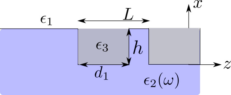 Figure 1
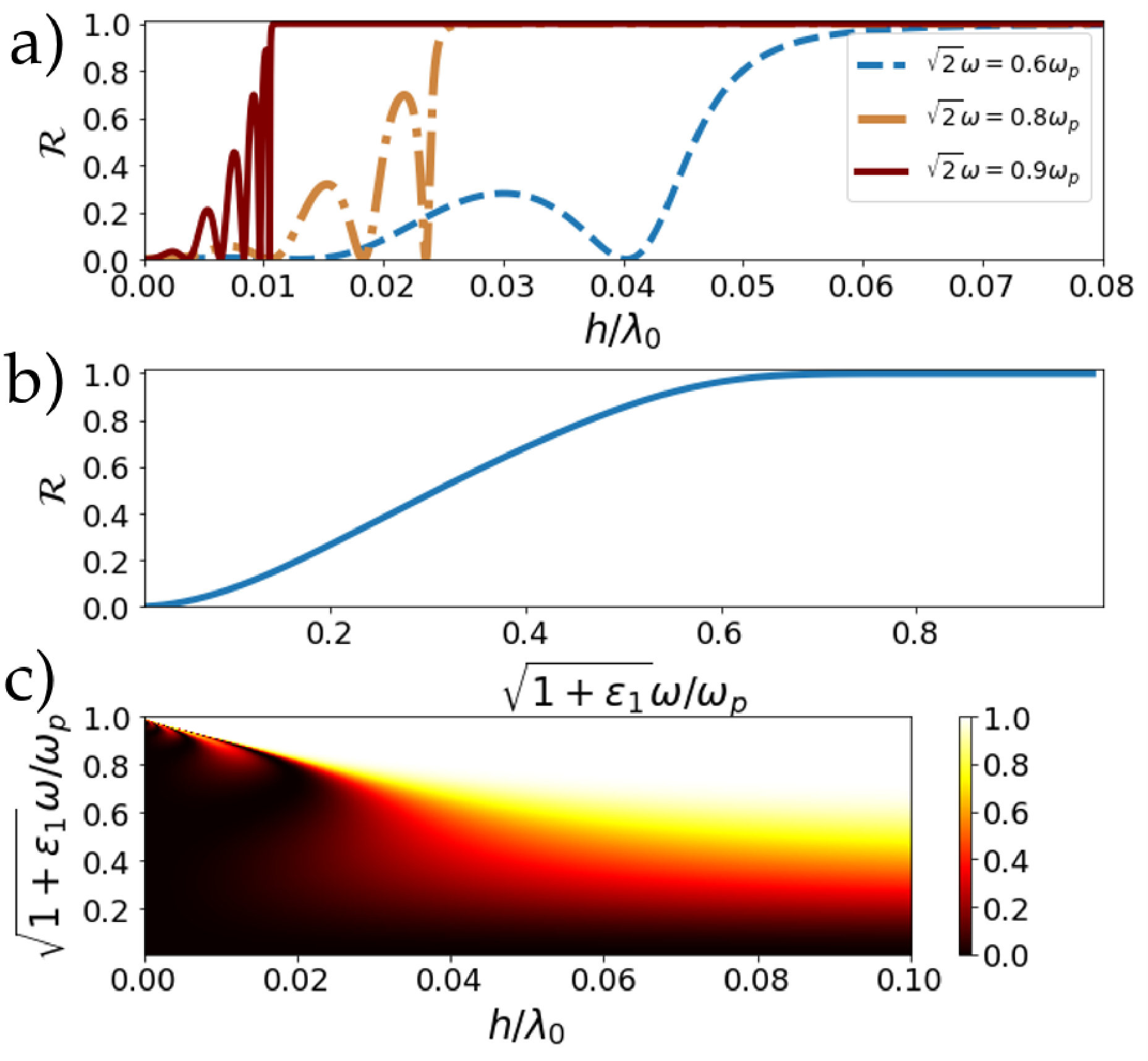 Figure 2
 Figure 3
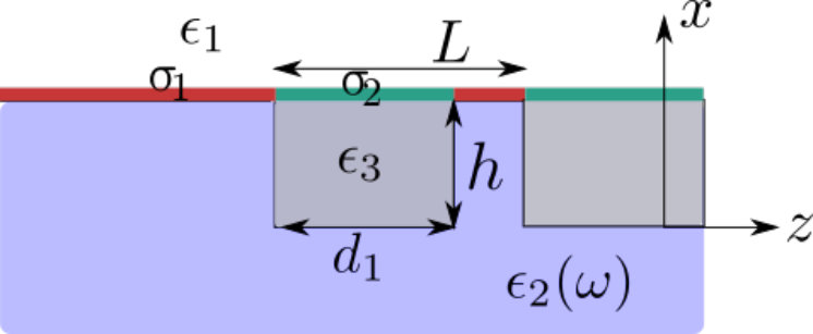 Figure 4
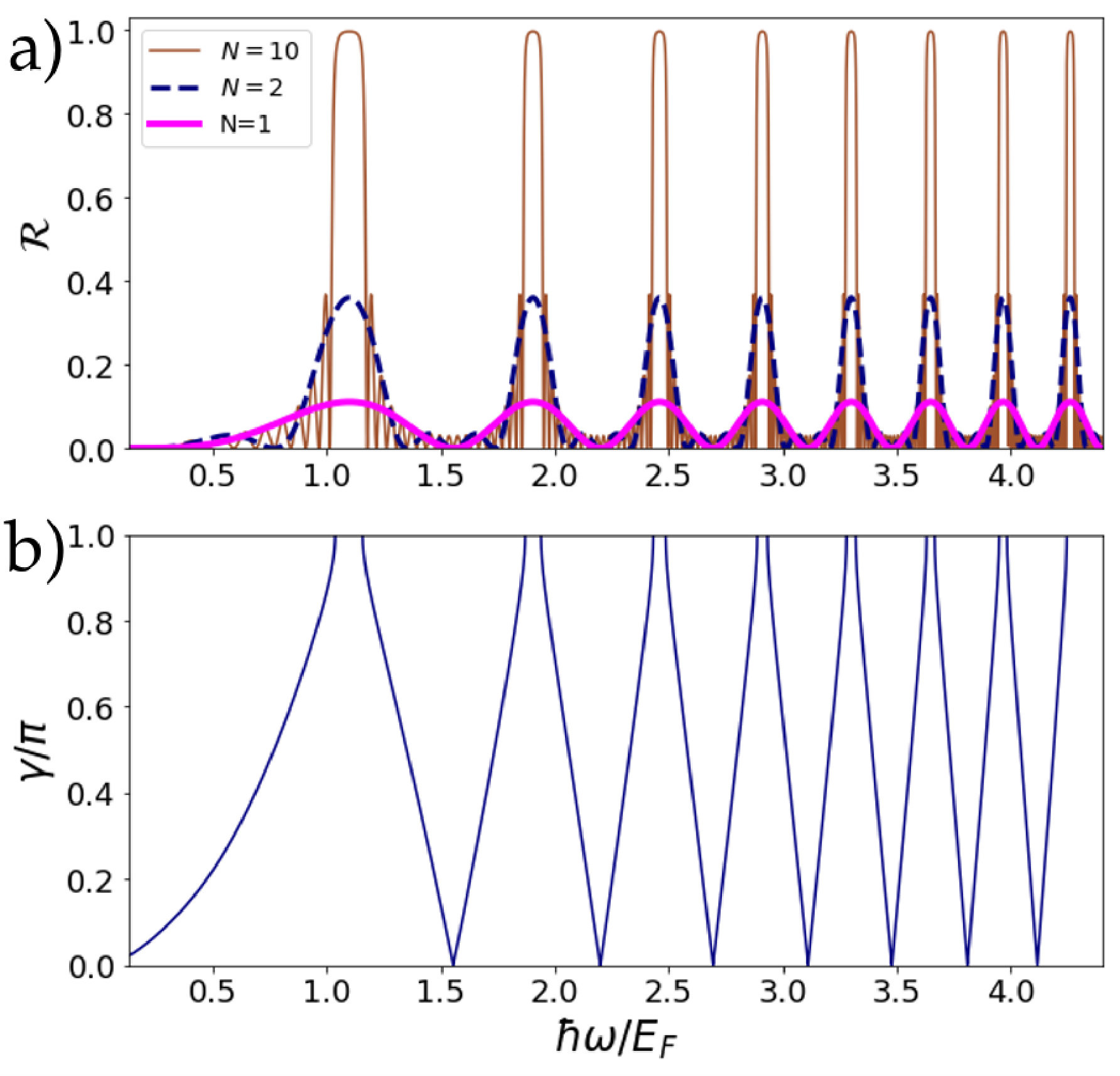 Figure 5
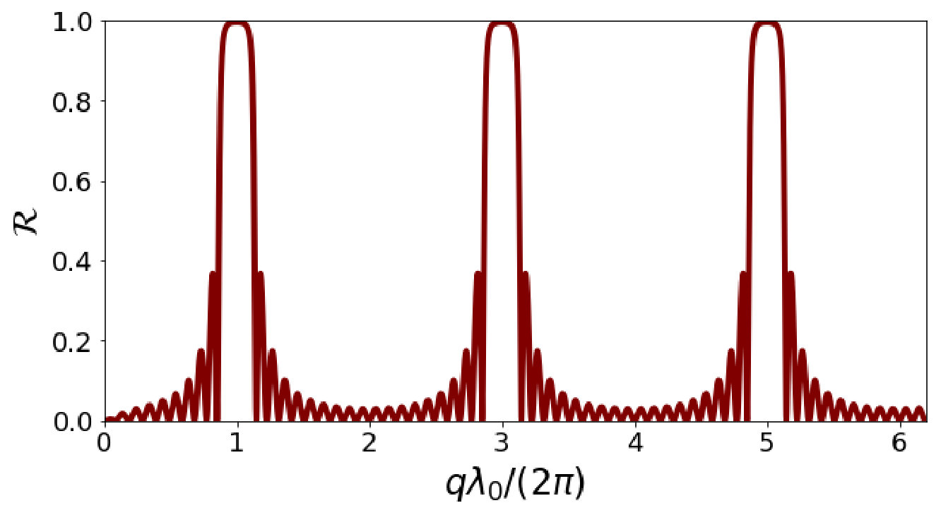 Figure 6
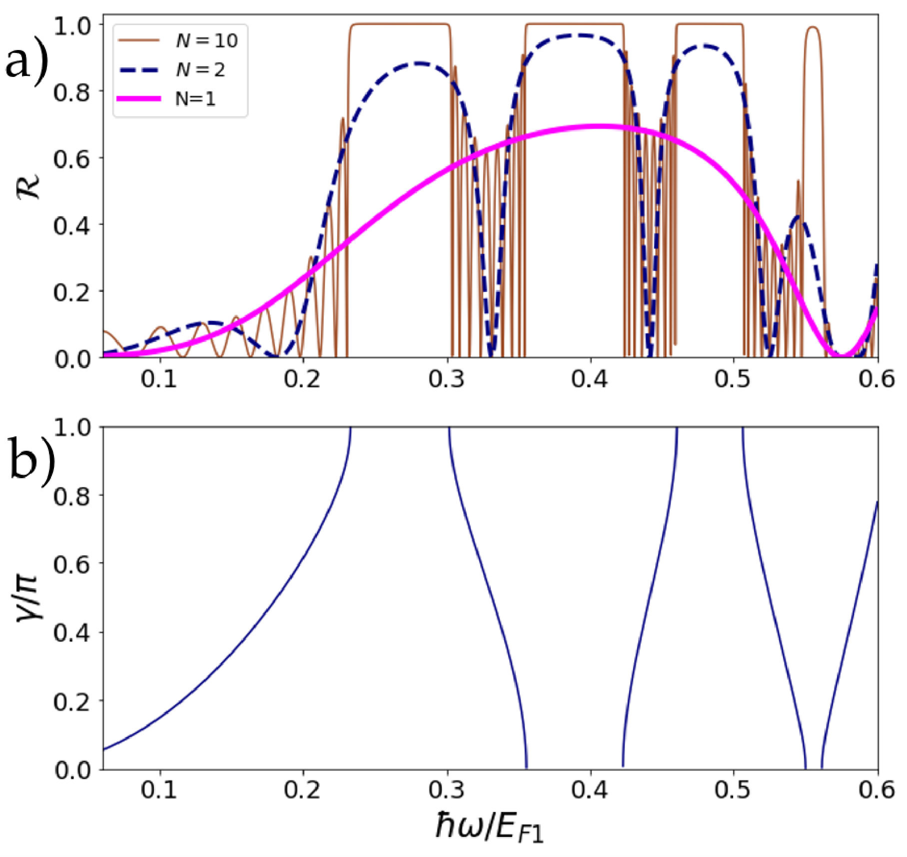 Figure 7
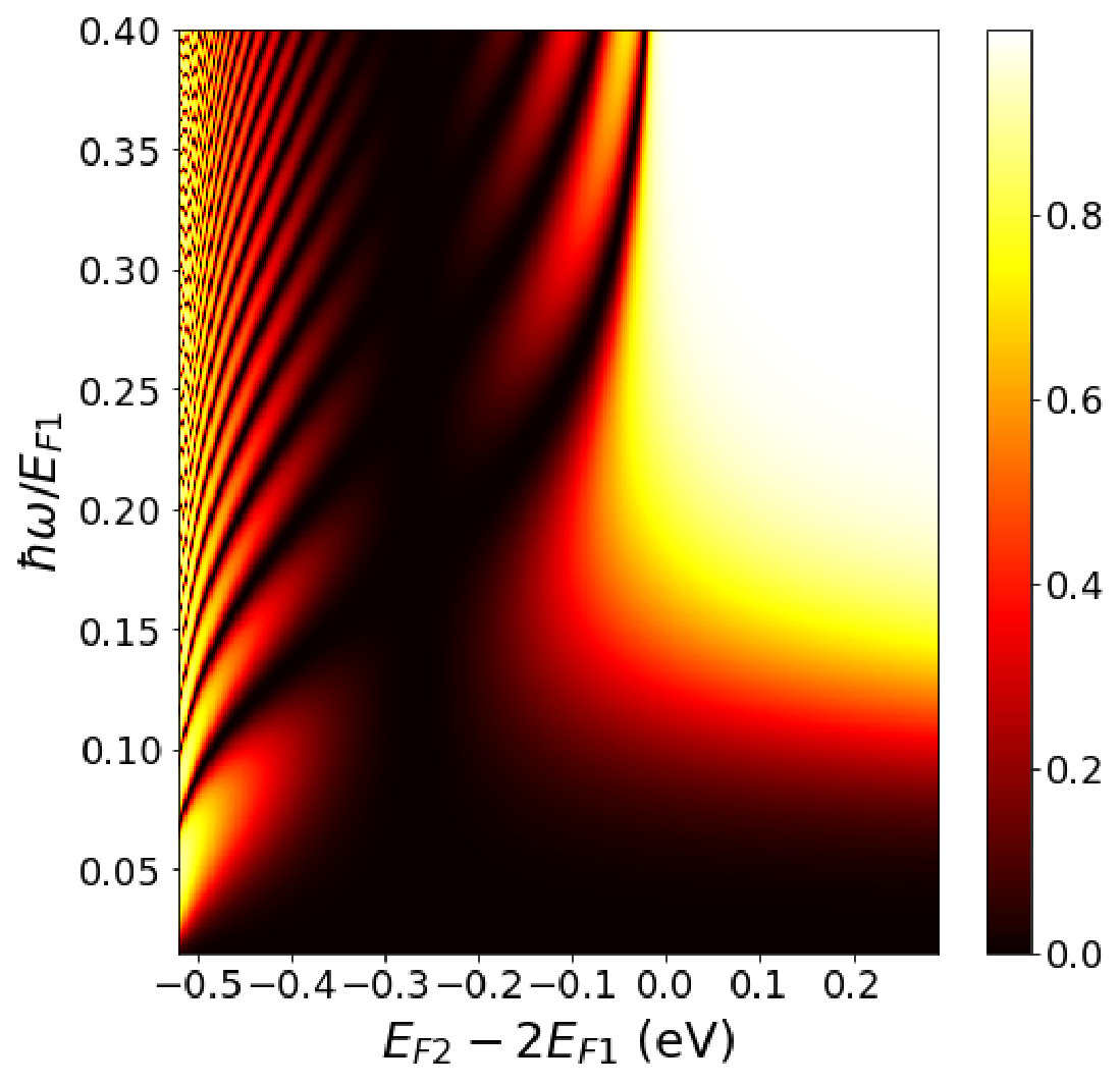 Figure 8
Peer Reviews
No public reviews on file for this paper yet. If you reviewed it on a platform where reviews are public (OpenReview, ICLR, NeurIPS, ICML), you can paste yours below so the community can read it here.
Videos
No videos yet. Explain this paper in a talk, walkthrough, or lecture? Add one.
Propagation of surface plasmons on plasmonic Bragg gratings
A. J. Chaves
Department of Physics, Instituto Tecnológico de Aeronáutica, DCTA, 12228-900 São José dos Campos, Brazil
Department and Centre of Physics, and QuantaLab, University of Minho, Campus of Gualtar, 4710-057, Braga, Portugal
N. M. R. Peres
Department and Centre of Physics, and QuantaLab, University of Minho, Campus of Gualtar, 4710-057, Braga, Portugal
International Iberian Nanotechnology Laboratory (INL), Av. Mestre José Veiga, 4715-330 Braga, Portugal
Abstract
We use coupled-mode theory to describe the scattering of a surface-plasmon polariton (SPP) from a square wave grating (Bragg grating) of finite extension written on the surface of either a metal-dielectric interface or a dielectric-dielectric interface covered with a patterned graphene sheet. We find analytical solutions for the reflectance and transmittance of SPP’s when only two modes (forward- and back-scattered) are considered. We show that in both cases the reflectance spectrum presents stop-bands where the SPP is completely back-scattered, if the grating is not too shallow. In addition, the reflectance coefficient shows Fabry-Pérot oscillations when the frequency of the SPP is out of the stop-band region. For a single dielectric well, we show that there are frequencies of transmission equal to 1. We also provide simple analytical expression for the different quantities in the electrostatic limit.
I Introduction
The usage of plasmonic technology depends on the possibility of controlling the propagation of surface-plasmon polaritons. Bragg grattings are a relatively simple way to control the propagation of light in both optical fibers hill1997 and metal-dielectric plasmonic interfaceshan2007 . When the conditions for destructive interference are fulfilled, the grating acts as a perfect mirror. In traditional Bragg gratings, the stop-band frequency can be engineered through the grating geometric parameters and a judiciously choice of dielectrics. For plasmonic graphene Bragg grattings, the stop-band depends on the carrier density (or the equivalently the Fermi energy of graphene) tao2014graphene , thus giving a new tool for in-situ control of the stop-band through a gate potential. We show in this paper that coupled-mode theory can be used to obtain analytic expressions describing the propagation of graphene plasmons as they propagate along the Bragg grating.
In a recent paper Feng coupled-mode theory Huang-94 was used for describing a set of experimental results showing unidirectional reflectionless in parity-time metamaterial at optical frequencies (see also Ref. Ramezani-2011 ). The metamaterial was itself made of a periodic arrangement of metallic nanostructures in an optical fiber. Coupled mode theory was quite popular in the seventies and the eighties of the last century and to our best knowledge it was first discussed by Yariv in the context of coupled waveguides Yariv-73 . However, with the advent of powerful numerical methods its use has declined. The paper of Feng et al. Feng gives a nice example where coupled-mode theory allows an analytical analysis of a scattering experiment with the obvious insight that an analytical solution provides over a fully numerical one.
In the context of guided wave optics, Taylor and Yariv provided Taylor-74 a detailed analysis of co- and contra-directional coupling, which corresponds to forward- and back-scattering of a single propagating mode induced by a periodic perturbation. Such perturbation can be introduced as a change of the dielectric function along the propagation direction or a Bragg grating imposed on the surface of the waveguide. The theory of electromagnetic propagation in periodic stratified media was first discussed by in great detail by Yeh, Yariv, and Hong Yeh . In the context of the theory of lasers, a comparison between the transfer matrix method and coupled-mode theory was given by MakinoMakino-94 . Recently, coupled-mode theory was used for studying the scattering of electromagnetic modes in a waveguide with corrugated boundaries Otto-2015 .
In this work, we discuss the application of coupled-mode theory to the back-scattering of a surface-plasmon polariton from a one-dimensional Bragg grating imposed on the surface of a metal-dielectric interface. As a second example, we consider a graphene sheet covering a finite Bragg grating and the back-scattering of a graphene surface-plasmon polariton is discussed. To our best knowledge, coupled-mode theory has not been applied so far to discuss the scattering of SPP’s. However, a recent work has used this approach to discuss the excitation of SPP in gratings by far-field coupling Lou-2016 . The coupling of a Gaussian laser beam to a SPP in a metallic film using coupled-mode theory was discussed by Ruan et al. Ruan-2014 . In the context of graphene physics, coupled-mode theory was recently used to discuss the excitation of localized plasmons of a graphene-based cavity with a Silver waveguide Chen-2018 .
Also, problems in the context of nonlinear optics can be treated using coupled-mode theory Hong-2018 . Integrating numerically the coupled-mode equations, Petracek and Kuzmiak have described Anderson localization of channel SPP’s in a disordered square-wave grating Petracek-2018 . In a different context, Graczyk and Krawczyk have studied Graczyk-2017 the propagation of magnetoelastic waves using the methods described in this article. The nonlinear interaction, promoted by a nonlinear second-order susceptibility tensor, between SPP’s was considered first by Santamato and Maddalena Santamato-1982 . Interesting enough, coupled-mode theory was adapted for describing coupling of Bose-Einstein condensates Kivshar-2000 . The same type of approach has been used for describing the field enhancement near plasmonic nanostructure under the effect of an external field Sun-2011 . The extension of the theory to chiral waveguides was achieved by Pelet and Engheta Pelet-1990 , and constitutes a nice application of Lorentz’s reciprocity theorem.
Coupled-mode equations are able to give both numeric and analytical results,that is, they can either be numerically integrated, thus giving exact results, or they can be solved in an approximate manner, thus giving approximate results. Both approaches have their own advantages. In this paper, our analytical results are approximated in the sense that only two modes, forward- and back-scattered modes, of the same frequency, are considered. This is a good approximation, since in the wave-guide only two SPP modes exist (forward and backward propagating SPP modes). However we do neglect the possible emission of radiation when the SPP impinges on the grating. Indeed, in the context of scattering of graphene’s SPP’s by abrupt interfaces, it has been shown that the coupling of the SPP to the radiation modes is weak Bludov ; Chaves and, therefore, the same is expected here. In Ref. [Chaves, ], we have found that for graphene plasmons the losses due to radiative emission is proportional to the contrast of the refractive index (or the conductivities ), but even when , the losses due to the radiative emission were less than 2%. In these systems, the main mechanism for losses is the intrinsic damping in the material. We note, however, that the formalism is general and there is no impediment to the inclusion of both radiative and evanescent modes in it. The price to pay may be the lack of an analytical solution.
The paper is organized as follows: in Sec. II we simplify the coupled-mode equations, expressing them in terms of forward and back-scattered amplitudes. In Sec. III we particularize coupled-mode equations to the case where only two degenerate modes in frequency are coupled and find a general solution using transfer-matrix method for a square-wave Bragg grating. In Sec. IV (Sec. V) the scattering of metallic SPP’s (graphene SPP’s) from a Bragg grating is discussed. We conclude the paper with a brief discussion in Sec. VI.
II Coupled-mode theory equations
The reader interested in a detailed derivation of the coupled-mode theory is invited to read the supplementary information. Here, we study a metal-dielectric or dielectric-dielectric interface, where a Bragg grating, extending over a finite region, is written on the surface of the metal/dielectric. In addition, we also study the case of alternating graphene strips with different conductivities deposited a the surface, as can be seen in Fig. 1.
For solving the scattering problem, we firstly solve the unpatterned waveguide problem, i.e., with translation symmetry along the axis. From this we obtain the corresponding electromagnetic normalized modes (see supplementary material) such that the power per unit length transported along the direction is . Afterwards, we decompose the propagating field inside the patterned heterostructure as function of the eigenmodes of the unperturbed waveguide:
[TABLE]
where the sum over has implicit summation and integration over both discrete and continuous modes, respectively. Each mode coefficient , can be decomposed as function of right and left propagating coefficients:
[TABLE]
and
[TABLE]
Substituting back Eqs. (1–4) in the Maxwell equations, we obtain the following coupled-mode equations:
[TABLE]
[TABLE]
where the coupling coefficients are
[TABLE]
where and
[TABLE]
Here, the power per unit length transported along the direction reads
[TABLE]
Equations (5) and (6) describe the propagation of a plasmonic wave along a heterostructure containing graphene layers. The specific geometry and dielectric information of the patterned heterostructure is encoded into the coupling coefficients and . For the specific case of a square-wave grating (Bragg grating), the integrals in (8) and (9) are analytical and they will be given in the following sections. As we will see in the next sections, for a square-wave grating it is possible to find an exact analytical solution of the system of equations (5) and (6).
III Solution for a square-wave Bragg grating
For a Bragg grating described by alternating dielectrics (where inside each dielectric slab the permittivity depends only on the transverse direction ) an exact solution can be obtained when only two modes are involved, a situation appropriate to our case. Let us consider:
[TABLE]
with an integer. The Bragg lattice has unit cells. In the lattice described by Eq. (11), the coefficient will be constant inside each slab. From now on we will consider only two modes, the forward and back-scattered with label . We simplify the notation so and . We define and when . Therefore, Eqs. (5) and (6) can be written as a set of coupled differential equations:
[TABLE]
The transmission and reflection coefficients can be defined as usual:
[TABLE]
Next, we solve Eqs. (12) and (13) for . From (13) we obtain:
[TABLE]
which can be combined into a single equation for using Eq. (12):
[TABLE]
and defining:
[TABLE]
the solution of Eq. (17) can be written as:
[TABLE]
with and constants. Substituting back in Eq. (16) we obtain:
[TABLE]
For obtaining the transfer matrix of the propagation between and , we need to write the components and as function of and . Therefore, using Eqs. (19) and (20) for we obtain:
[TABLE]
where we have defined . For we find:
[TABLE]
From Eqs. (21) we have:
[TABLE]
and using Eqs. (24) in Eqs. (22) we obtain after some algebra:
[TABLE]
where we have defined and , with . This defines the propagation along any unit cell from to . The propagation from to is given from the solution of:
[TABLE]
where the coupling constants vanishes because of the dielectric function (11). Therefore, we have the trivial solution: and . The total transfer matrix of the propagation along an entire unit cell is:
[TABLE]
where we defined and , such that the transfer matrix relating the right and left propagating fields impinging on each face of a unit cell is (the super-index refers to the transpose operation):
[TABLE]
From the eigenvalues of the above matrix we can obtain the Bloch phase :
[TABLE]
and from the Chebyshev identity Soukoulis we can obtain the transmission and reflection coefficients for the propagation along unit cells:
[TABLE]
Therefore, we have obtained analytical formulas for the propagation of two coupled modes. This formalism will be used in the next two sections to obtain the propagation properties of SPPs in metallic and graphene gratings.
IV SPP scattering from a metallic grating
In this section we consider the scattering of a SPP from a Brag grating whose unit cell is represented in Fig. 1. The dielectric function is vacuum, the dielectric represents the optical response of the metal below the plasma frequency, and is another dielectric, in principle different from and .
IV.1 SPP fields and dispersion relation
Let us consider an interface between a metal and a dielectric. The relative dielectric function of the metal is in the spectral range where and that of the dielectric is , and is assumed constant. The dispersion relation of a surface-plasmon polariton at a metallic interface with a dielectric is given by Peres
[TABLE]
The field of the SPP has the form Peres
[TABLE]
where defines the medium where the field is located. Using Maxwell’s equations, we obtain
[TABLE]
We note that and are the transverse fields, whereas is the longitudinal component. The usual boundary conditions for the fields at an interface, and , lead to the dispersion relation (30). Note that and must have different signs for satisfying the first boundary condition. Therefore, an SPP mode only exists when its frequency is below the plasma frequency. Indeed, we can show from Eq. (30) that the frequency region for the existence of the SPP obeys the condition
[TABLE]
where is the plasma frequency of the metal. The determination of the magnitude follows from the normalization condition (see the supplementary information for a review), which has the form
[TABLE]
or, in the case of the SPP field,
[TABLE]
which leads to
[TABLE]
IV.2 Dielectric profile
The system upon which the SPP will scatter is a square dielectric grating of period . As a function of , the dielectric profile reads
[TABLE]
with . Once the dielectric profile is known, we can compute the coupling constants and using Eqs. (8) and (9). Since , the coupling constants are also periodic. In this case, because the dielectric functions vary in a step-like manner, they can be computed analytically, reading
[TABLE]
and
[TABLE]
from where the coupling constant (7) follows; the parameter is the height of the dielectric well/barrier. We note that the coupling constants and are zero when or , which corresponds to the perfect interface. Therefore, the reflectance coefficient is zero in these cases.
IV.3 Results for a single barrier
We first consider the case of a single well of width and height . The results for the reflectance coefficient are given in Fig. 2. In the first panel we see that when , as discussed above. Also there are heights different from zero for which there is perfect transmission. A similar phenomenon occurs when electrons are scattered from a potential well. From the central panel of the same figure we see that when , which makes sense since in this case we have essentially free radiation of very large wavelength and, therefore, unable to see the dielectric well. As approaches we have . The last panel shows a study of as function of and , showing that for the reflectance becomes insensitive to further increases in the well height. The almost absence of oscillations of the reflectance comes from the fact that [see Eq. (18)] for the parameters used, such that the fields inside the well are evanescent, as discussed in detail in the next subsection.
IV.4 Results for a Bragg grating
For a Bragg grating the transmission and reflection can be obtained from Eqs. (28) and (29), with the Bloch phase given by Eq. (27). The propagation inside the dielectric well is determined by the value of . For we have sinusoidal transmission while for we have evanescent transmission, with determining the crossing between those two regimes. When and the function will always be negative, resulting in evanescent transport inside the dielectric well. In this section we will study the case when the dielectric is also given by a metal with a corresponding dielectric function .
We show the results for the reflectance and dispersion relation in Fig. 3. We consider eV and eV. The Bragg grating has , , , where is the wavelength of the plasmon (30) for a frequency of and eV. We have that for and . The divergence in explains the large number of bands slightly below the energy of eV in the bottom panel of Fig. 3. Note the correlation between the presence of stop-bands in the spectrum of the SPP and the value of 1 for the reflectance.
V Scattering of graphene plasmons from a dielectric Bragg grating
Now we consider a system with the geometry of Fig. 1 but with a graphene sheet on top. Also, we consider that conductivity of graphene is () when on top of the dielectric (), as shown in Fig. 1 . The presence of a graphene sheet corresponds to including a surface current in the Maxwell equation:
[TABLE]
where is the 2D graphene conductivity and the sheet is located at the plane .
We consider, for simplicity, that the graphene conductivity is given by the Drude formula Peres :
[TABLE]
with , () the Fermi energy in the graphene sheet relative to the Dirac Point, and is the relaxation rate. From now on we will consider as we are not interested in studying the effect of intrinsic losses. In this case, the boundary condition at the graphene interface leads to a different dispersion relation (when compared to the metallic case) given by Peres
[TABLE]
whose solution in the electrostatic limit reads Peres
[TABLE]
where is the fine structure constant and is the Fermi energy of doped graphene. We note that, in addition to a modification of the dispersion relation, graphene plasmons exist as well defined excitation for energy scales smaller than the Fermi energy, and therefore in a different frequency range from that observed for noble metal plasmonics.
We can define a new dielectric tensor taking in account the graphene’s conductivity:
[TABLE]
with the unit vector along the plane that contains the graphene sheet and where the last dot means a inner product when applied to a vector field. Therefore Eq. (43) becomes .
With the presence of a graphene sheet, the tangential magnetic field is no longer continuous. Thus, we need to calculate the new normalization in the sense of Eq. (37), reading:
[TABLE]
and the other components of the electromagnetic field can be calculated from:
[TABLE]
with . Using Eqs. (48) and (49) in Eqs. (8) and (9) we obtain:
[TABLE]
[TABLE]
where , with , is the Drude conductivity (44).
In the following we will show how the formalism works for two examples. First when and . Next we show the results for and .
V.0.1 Different substrates and same conductivity
Firstly we show the results in Fig. 4 for a grating with and and . We can see that the bandwidths decreases as we increase the SPP frequency. In the electrostatic limit and we can simplify the coefficients , to:
[TABLE]
[TABLE]
with and when . In this case we have that the functions and are:
[TABLE]
and we can calculate from Eq. (18):
[TABLE]
with:
[TABLE]
and thus the functions and that appear inside the transfer matrix (III) are given by:
[TABLE]
note that as (or ) increases we have . If we ignore the dependence on frequency of the dielectrics constants, the functions and will become frequency independent and also do the propagation properties that are expressed in the transfer matrix approach by Eq. (28). This depends only on the angles , both proportional to . We show the periodic dependence of the reflection as function of in Fig. 5. In the same figure the stop-band appears for , with an integer. As before, there is a correlation between the presence of stop-band and the reflectance equal to 1.
V.0.2 Different conductivities and same substrate
Next we show in Fig. 6 the results for a grating of alternating strips of graphene with different Fermi energies deposited on the same substrate with dielectric constant . For the widths we used , where m is the graphene plasmon wavelength obtained from Eq. (46) for eV and . We can see that the first stop-band is centered in the frequency . Compared to the previous section, we did not impose the phase matching condition. Therefore, there is no simple relation between the stop-band frequency and for the chosen parameters. However, we will show in the following that such condition can also be obtained in this case.
In the electrostatic limit we can obtain , , and when as:
[TABLE]
with obtained using with in Eq. (46).
In this limit the functions do not depend on the plasmon frequency and , with . As we discussed in the previous section, we can also find the condition for the phase matching :
[TABLE]
Thus, we can engineer a stop-band for any given frequency adjusting . Also, as discussed in the previous subsection, the spectra for becomes periodic with respect to , a result that comes from the parameters becoming frequency independent.
In Fig. 7 we show the reflectance as function of and the plasmon frequency. When , we have that , given by Eq. (60), is negative, implying evanescence transport and explaining the large bright area with .
For , we have that , meaning that the wavelength in the region with will be significantly smaller than the wavelength of the incoming plasmon, making the system acting as a Fabry-Pèrot cavity, explaining the large number of fringes around eV, that is, when . When , that happens for eV and the reflectance goes to zero, as expected. We can also see that in respect to the difference the reflectance is asymmetric. This also happens for an electron scattering through a square well: the reflectance have different behavior if the square well is positive or negative.
VI Conclusions
We have used coupled-mode method and transfer matrix theory for describing the scattering of a metallic SPP and a graphene SPP from a square-wave Bragg grating written on the interface between a metal and a dielectric and between two different dielectrics, respectively. The method allows for simple analytical expressions for the reflection coefficient and the dispersion relation of the Bragg grating. Our results are valid within the approximations that the coupling of the SPP mode to radiation and evanescent modes is small. Relaxing this approximation is possible, but analytical results are no longer available.
We used the analytical results to study the reflection and dispersion relation for different plasmonic Bragg gratings. We characterized the condition for having sinusoidal or evanescent transport. For a Bragg grating consisting of alternating metals with different plasmonic frequencies, we show that there will be an infinite number of bands when the grating metal has a lower plasmonic frequency than the substrate metal.
We have also shown that the transfer matrix parameters for graphene SPPs are frequency independent in the electrostatic limit. With this result we could find the condition for phase matching of the traveling wave inside each component of the Bragg grating, thus finding the condition for engineering a stop-band for any given frequency.
Finally, comparing our model with a fully numerical calculation tao2014graphene we find the same qualitative behavior, with two small differences: 1) the reflection obtained with our method is larger; 2) the stop band frequency is slightly different. These small differences are due to the consideration of losses in Ref. tao2014graphene . On the other hand, it is well known that graphene plasmons on h-BN have very low losses woessner2015highly . Therefore, if we consider a h-BN buffer layer between graphene and the Bragg grating we expect our model to show a fully quantitative agreement with numerical solver software.
VII Suplementary material
A detailed presentation of coupled mode theory is given in the supplementary information.
Acknowledgments
N.M.R.P. acknowledges Bruno Amorim for discussions in the early stage of the this work. Both authors thanks D. T. Alves for corrections. N.M.R.P. acknowledges support from the European Commission through the project “Graphene-Driven Revolutions in ICT and Beyond” (Ref. No. 785219), COMPETE2020, PORTUGAL2020, FEDER and the Portuguese Foundation for Science and Technology (FCT) through project POCI-01-0145-FEDER-028114 and in the framework of the Strategic Financing UID/FIS/04650/2013.
The reference list from the paper itself. Each links out to its DOI / PubMed record.
- 1(1) K. Hill and G. Meltz, Fiber Bragg grating technology fundamentals and overview , Journal of lightwave technology 15 , 8 (1997).
- 2(2) Z. Han, E. Forsberg, and S. He, Surface plasmon Bragg gratings formed in metal-insulator-metal waveguides , IEEE Phot. Tech. Lett. 19 , 2 (2007).
- 3(3) J. Tao, X. Yu, B. Hu, A. Dubrovkin and Q. J. Wang, Graphene-based tunable plasmonic Bragg reflector with a broad bandwidth , Optics letters 39 , 2 (2014).
- 4(4) L. Feng, Y.-L. Xu, W. S. Fegadolli, M.-H. Lu, J. E. B. Oliveira, V. R. Almeida, Y.-F. Chen, and A. Scherer, Experimental demonstration of a unidirectional reflectionless parity-time metamaterial at optical frequencies , Nat. Matt. 12 , 108 (2013).
- 5(5) W.-P. Huang, Coupled-mode theory for optical waveguides: and overview , J. Opt. Soc. Am. A 11 , 963 (1994).
- 6(6) Z. Lin, H. Ramezani, T. Eichelkraut, T. Kottos, H. Cao, and D. N. Christodoulides, Unidirectional Invisibility Induced by PT-Symmetric Periodic Structures , Phys. Rev. Lett. 106 , 213901 (2011).
- 7(7) A. Yariv, Coupled-Mode Theory for Guided-Wave Optics , IEEE Journal of Quantum Electronics QE-9 , 919 (1973).
- 8(8) H. F. Taylor and A. Yariv, Guided Wave Optics , Proceedings of the the IEEE 62 , 1044 (1974).