Analytical and numerical $K_u - B$ phase diagrams for cobalt nanostructures: stability region for a Bloch skyrmion
A. Riveros, N. Vidal-Silva, F. Tejo, J. Escrig

TL;DR
This paper analytically and numerically constructs phase diagrams for cobalt nanostructures, identifying stability regions for skyrmions, vortices, and ferromagnetic states under varying anisotropy and magnetic fields.
Contribution
It introduces a method to calculate magnetic phase diagrams for cobalt nanostructures, highlighting stability regions for skyrmions and other magnetic configurations.
Findings
Stability regions for Bloch skyrmions, vortices, and ferromagnetic states identified.
Phase diagrams constructed as functions of anisotropy and magnetic field.
Results enable control of skyrmion formation in cobalt nanostructures.
Abstract
In this letter we calculate the energies corresponding to the different magnetic phases present in a ferromagnetic cylinder by means of analytical calculations. From the comparison of these energies, it is possible to construct magnetic phase diagrams as a function of the uniaxial anisotropy of the sample and the external magnetic field applied. As proof of concept, we analyzed the magnetic phase diagrams for a cobalt dot of 240 nm in diameter and 70 nm in length, with an easy axis parallel to the dot axis, and with a magnetic field applied towards or perpendicular to this axis. From these diagrams we have obtained the stability regions for a Bloch skyrmion (Sk), a vortex core (VC) and a ferromagnetic (F) configuration, which can point in any direction. Our results provide a pathway to engineer the formation and controllability of a skyrmion in a ferromagnetic dot to different…
Click any figure to enlarge with its caption.
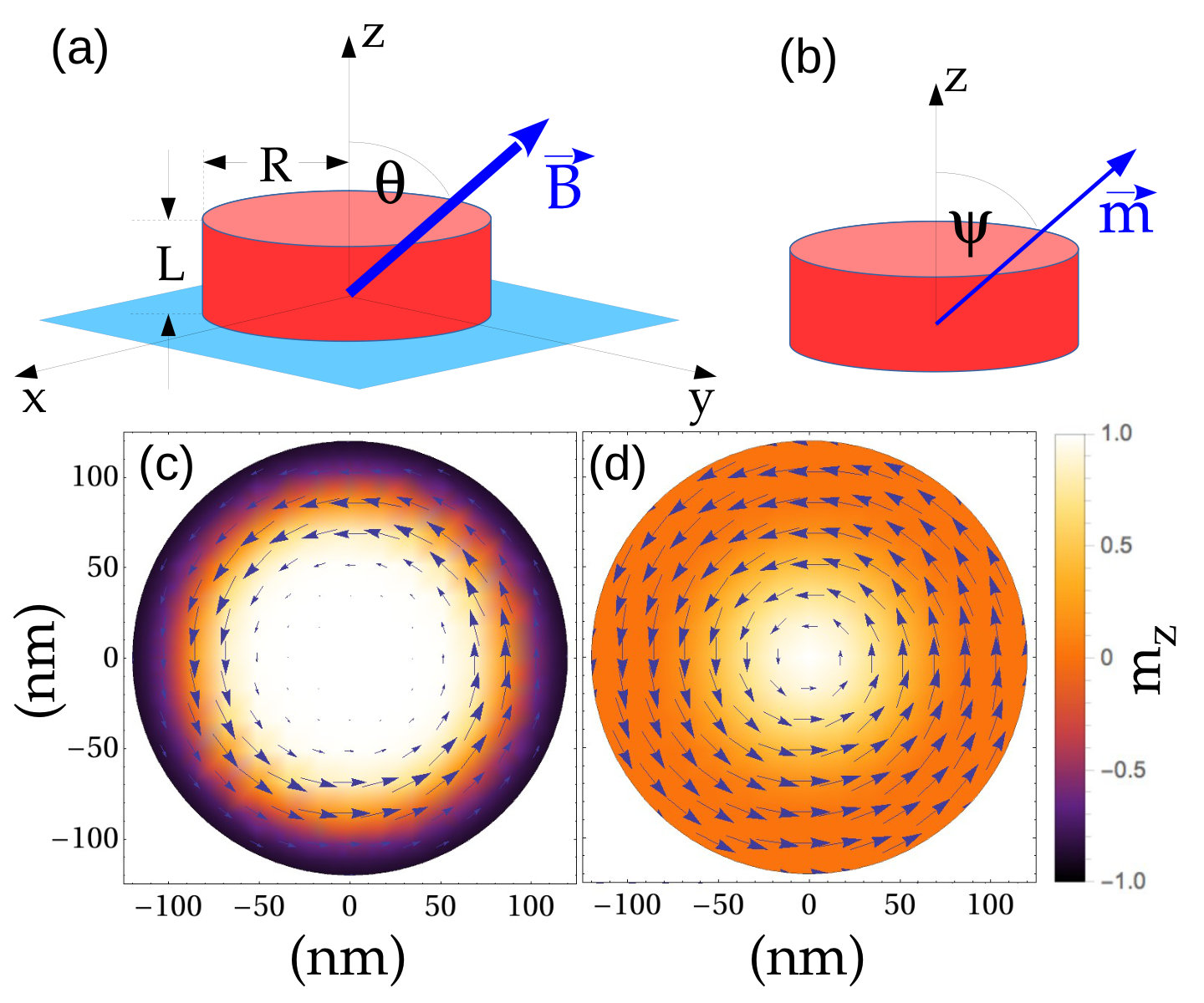 Figure 1
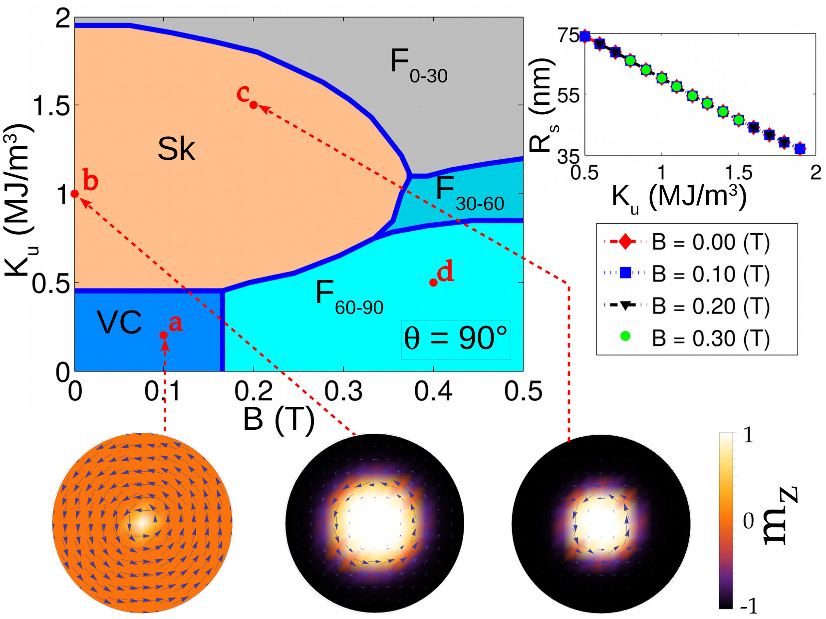 Figure 2
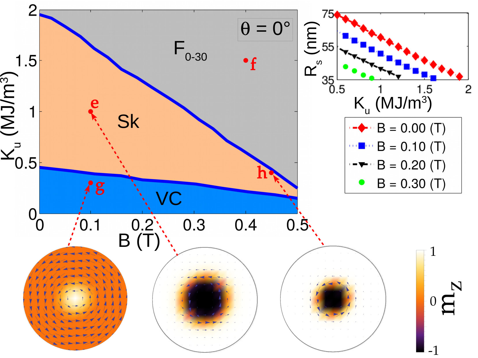 Figure 3
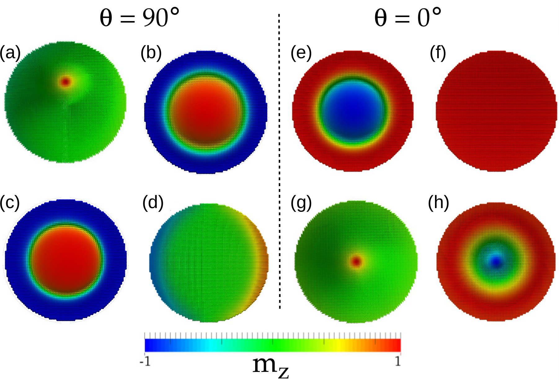 Figure 4
Peer Reviews
No public reviews on file for this paper yet. If you reviewed it on a platform where reviews are public (OpenReview, ICLR, NeurIPS, ICML), you can paste yours below so the community can read it here.
Videos
No videos yet. Explain this paper in a talk, walkthrough, or lecture? Add one.
Analytical and numerical phase diagrams for cobalt nanostructures: stability region for a Bloch skyrmion
A. Riveros1
N. Vidal-Silva1
F. Tejo1
J. Escrig1,2
1Departamento de Física, Universidad de Santiago de Chile (USACH), Av. Ecuador 3493, 9170124 Santiago, Chile
2Center for the Development of Nanoscience and Nanotechnology (CEDENNA), 9170124 Santiago, Chile
Abstract
In this letter we calculate the energies corresponding to the different magnetic phases present in a ferromagnetic cylinder by means of analytical calculations. From the comparison of these energies, it is possible to construct magnetic phase diagrams as a function of the uniaxial anisotropy of the sample and the external magnetic field applied. As proof of concept, we analyzed the magnetic phase diagrams for a cobalt dot of 240 nm in diameter and 70 nm in length, with an easy axis parallel to the dot axis, and with a magnetic field applied towards or perpendicular to this axis. From these diagrams we have obtained the stability regions for a Bloch skyrmion (Sk), a vortex core (VC) and a ferromagnetic (F) configuration, which can point in any direction. Our results provide a pathway to engineer the formation and controllability of a skyrmion in a ferromagnetic dot to different anisotropy constants and magnetic fields.
I Introduction
Skyrme was the first to describe the baryons as topological defects of continuous fields skyrme62 . Since then, skyrmions have been found in various systems, such as ferroelectrics NPL+15 , liquid crystals ATS+14 , magnetic materials NYT12 , among others. For example, topological magnetic skyrmions FBT+16 have been observed in several bulk MBJ+09 ; MNA+10 ; YOK+10 ; SYI+12 and thin film YKO+11 ; FSK+13 ; JUZ+15 ; MMR+16 ; WLK+16 ; WZX+16 systems, and have been proposed for potential applications in non-volatile magnetic memories RHM+13 because the spin texture topology protects the skyrmions from scattering with structural defects, allowing them to be moved by small current densities, opening a new paradigm for the manipulation of magnetization at the nanoscale JMP+10 . Besides, skyrmions exhibit emergent electromagnetic phenomena, such as topological Hall effect and the skyrmion Hall effect NT13 ; LLK+17 , and have been proposed as information carriers in novel magnetic sensors and spin logic devices ZEZ15 .
Isolated skyrmions confined in cylindrical nanostructures WLK+16 ; MMR+16 ; SCR+13 ; RT13 ; DWT+13 ; Guslienko15 ; BCW+15 ; SA16 ; BVY+16 ; GG16 are considered to be promising for implementations in information storage and processing devices on the nanoscale FCS13 ; SCF+13 . In these nanostructures both the Dzyaloshinskii-Moriya interaction (DMI) and the magnetic anisotropy are required to stabilize a Neel skyrmion (NS) RT13 ; SCR+13 ; BCW+15 , where the magnetic profile has a magnetic component in the radial direction, so they cannot be seen in conventional ferromagnetic materials (Co, Ni, etc.). On the other hand, the Bloch skyrmions (BS), which do not have magnetic component in the radial direction, can be stabilized in the absence of DMI, provided there is a magnetic anisotropy Guslienko15 ; SA16 ; DWT+13 . These systems show potential for room temperature control of skyrmions MWY+15 ; GMB+15 .
In this letter, we are interested in obtaining analytical expressions for the energies of different magnetic configurations (ferromagnetic pointing in any direction, vortex core and Bloch skyrmion without DMI) in a cobalt nanodot that allow us to generate magnetic phase diagrams with regions of stability for each configuration as a function of the uniaxial anisotropy and the external magnetic field. In addition, we will carry out micromagnetic simulations for some particular cases, in order to be able to support the theoretical model used.
II Analytical model
We adopt a simplified description of the system, where the discrete distribution of the magnetic moments is replaced with a continuous one characterized by a slow variation of the magnetization Aharoni96 , whose direction is given by the unitary vector while that corresponds to the saturation magnetization. Due to the cylindrical symmetry of the nanoparticle, it is convenient to rewrite the magnetization vector as , where , and are the unitary vectors of the cylindrical coordinates.
We consider a cylindrical nanoparticle of radius and length which exhibits an uniaxial anisotropy whose axis of easy magnetization is parallel to the symmetry axis of the particle (chosen as the z-axis), and which is under the action of an external magnetic field applied at an angle with respect to the -axis, as shown in Fig. 1a. The total energy for this nanoparticle is given by
[TABLE]
wherein the first, second, third and fourth term corresponds to the uniaxial anisotropy, the dipolar energy, the exchange energy and the Zeeman energy, respectively. Here , and are the anisotropy constant, stiffness constant and magnetic permeability, respectively, while is the well-known magnetostatic potential defined as Aharoni96 , with being the Green function. In the previous definition of , the first integral is over the surface of the nanoparticle, while the second is on its volume.
We are interested in obtaining phase diagrams showing the stability regions for the following magnetic configurations: skyrmion (Sk), ferromagnetic (F) and vortex core (VC).
II.1 Skyrmion configuration (Sk)
For the description of a skyrmion configuration we have used the Ritz model proposed in VRE17 :
[TABLE]
where is the radius of skyrmion and is a positive even integer number, . It is important to mention that the components in the plane of the magnetization are given by and . As an example, in Fig. 1c we show the profile of the magnetization of a skyrmion, in a nanoparticle of nm, obtained from the Eq. 2 for and nm. The component is shown as a density color plot, while the component is represented by arrows.
II.2 Ferromagnetic configuration (F)
As we have considered a competition between the uniaxial anisotropy (which favors the magnetization to point along the -axis) and the external magnetic field, which forms an angle with respect to the -axis, as shown in Fig. 1a, we have used a ferromagnetic configuration whose direction is allowed to point at an angle with respect to the -axis, as shown in Fig. 1b.
[TABLE]
II.3 Vortex core configuration (VC)
Finally, we have also considered a vortex core configuration, for which we have used the Ritz model previously investigated by LEA+05 ; MAL+10 ; RVL+16
[TABLE]
where and , while corresponds to the core size. As an example, in Fig. 1d we show the profile of the magnetization of a vortex core, in a nanoparticle of nm, obtained from the Eq. 4 for nm.
To obtain the minimum energy configuration for a given set of geometric parameters ( and ) and magnetic (, , and ), we calculate the energy of each magnetic configuration, for which we replace the corresponding ansatz (Eqs. 2, 3 and 4) within Eq. 1, and we minimize with respect to , and , respectively. In the case of skyrmion, we have to choose a value of , for which we have performed an analysis similar to the one performed in VRE17 , obtaining that is a reliable value to correctly describe a skyrmion state.
III Micromagnetic simulations
In order to validate the analytical calculations, we have investigated the minimum energy configuration of a cobalt dot of radius nm and length nm by micromagnetic simulations oommf . In this article we have considered an out-of-plane magnetic anisotropy, which is generally obtained when the cobalt is deposited on a platinum or palladium substrate Fang2013 ; OMS+99 ; KMZ+17 ; MOV+17 . We have used a saturation magnetization A/m, an exchange stiffness J/m and a Gilbert damping constant = 0.5. In addition, we use four possible initial magnetic configurations (skyrmion, vortex core, ferromagnetic out of plane and ferromagnetic in plane), which are allowed to relax as a function of and values, to finally compare the total energies between the different final configurations to which the system evolved. In order to obtain the results in a reasonable time, the discretization of the system was nm3. The phase diagrams showed in Section IV were obtained using the analytical equations of Section II, nevertheless some points of these diagrams were also obtained through micromagnetic simulations.
IV Results and phase diagrams
The equations presented in section II are quite general and allow to investigate a magnetic dot with different geometric and magnetic parameters. As an example, and by comparing the energy curves for the different magnetic configurations, we have obtained the phase diagrams for the studied cobalt nanostructures ( A/m and J/m) of radius nm and length nm, in the range of MJ/m3 and T for both and , which are shown in Figs. 2 and 3, respectively. In these phase diagrams we have called , and to the ferromagnetic configuration with , and , respectively. The transition lines between two magnetic configurations were obtained analytically using steps of T and MJ/m3 for and , respectively.
As can be seen from Fig. 2, when the magnetic field is in the in-plane direction, for values of MJ/m3 and T the cobalt nanostructure presents a VC configuration, whereas if the uniaxial anisotropy constant increases, a Sk-phase is reported, which is stable even for magnetic fields close to T. On the other hand, due to the competition between uniaxial anisotropy (which favors a magnetization parallel to the -axis) and the external magnetic field (which favors a magnetization perpendicular to the -axis), a stable ferromagnetic phase appears, whose magnetization points in the whole range of angles, that is, .
On the other hand, in Fig. 3 we analyze the situation if the magnetic field points in the same direction as the uniaxial anisotropy (-axis). In this case, and although the VC phase is still present only for low values, it is now stable for the entire range of magnetic fields investigated. If we increase the value of , a fairly extensive region appears where the Sk-phase is stable, covering the entire range of magnetic fields investigated. It is important to mention that when , the only surviving ferromagnetic phase is . From both figures, we can conclude that for , the Sk-phase is not stable, regardless of whether the magnetic field is applied at or at .
The inset plots of Figs. 2 and 3 show the behavior of the Sk-radius as a function of the uniaxial anisotropy constant , for different values of when and , respectively. As can be seen decreases as increases, nevertheless for , does not depend on the intensity of the magnetic field, instead for , where the -curves change for different -values. Indeed decreases as increases, due to the core of the Sk-magnetization () points in the opposite direction of the magnetic field, in order to minimize its energy. We have compared the Sk-energy curves for cores pointing in both directions ( and ), founding that in the whole Sk-phase of Fig. 3, the Sk-energy curve with core in the opposite direction of is always below of the corresponding Sk-energy curve with core in the same direction of the field, while for , both Sk-energy curves have the same values.
Importantly, from the developed micromagnetic simulations, and for the geometric and magnetic parameters investigated in this paper, we have only obtained the theoretically proposed magnetic configurations, and we have not observed complex phases such as the helical magnetic phase. In addition, it is worth mentioning that the numerical results (showed in Fig. 4) for the marked red points in Figs. 2 and 3 have an extraordinary agreement with the analytical phase diagrams. Figure 4a shows that the vortex core is slightly offset from the center of the cylinder, which could slightly reduce the energy of this configuration. This breaking of azimuthal symmetry is out of the focus of this article.
Conclusions
In conclusion, by the analytical calculation of the energies corresponding to the different magnetic phases present in a ferromagnetic dot, we were able to prepare the magnetic phase diagrams for a cobalt dot of radius nm and length nm presenting the stability region for a Bloch skyrmion (Sk), a vortex core (VC) and a ferromagnetic (F) configuration. In general, and regardless of the angle at which the external magnetic field is applied, a cobalt dot will exhibit a Bloch skymion for MJ/m3 and low magnetic field values. It is important to mention that the radius of the skyrmion decreases with an increase in the uniaxial anisotropy constant, and as the magnetic field intensity increases (for a magnetic field pointing towards the -axis), for which case we found that the skyrmion core points in the opposite direction of the magnetic field. This preferred core direction disappears when the magnetic field points in the direction perpendicular to the symmetry axis, and the skyrmion radius becomes independent of the intensity of the magnetic field. In addition, the results have been validated by micromagnetic simulations, which exhibit an excellent agreement with the analytical results. Finally, these analytical results which allow to obtain magnetic phase diagrams with the stability region of Bloch skyrmions, will be key for the design of future devices based on the manipulation of the magnetic skyrmions.
Acknowledgements
We thank V. Salinas-Barrera for his insightful commments. This work was supported by Fondecyt Grant 1150952, DICYT Grant 041731EM-POSTDOC from VRIDEI-USACH, Financiamiento Basal para Centros Científicos y Tecnológicos de Excelencia FB0807, and Conicyt-PCHA/Doctorado Nacional/2014.
The reference list from the paper itself. Each links out to its DOI / PubMed record.
- 1(1) T. H. R. Skyrme, Nucl. Phys. 31 , 556 (1962).
- 2(2) Y. Nahas, S. Prokhorenko, L. Louis, Z. Gui, I. Kornev, and L. Bellaiche, Nat. Commun. 6 , 8542 (2015).
- 3(3) P. J. Ackerman, R. P. Trivedi, B. Senyuk, J. van de Lagemaat, and I. I. Smalyukh, Phys. Rev. E 90 , 012505 (2014).
- 4(4) N. Nagaosa, X. Z. Yu, and Y. Tokura, Philos. Trans. A 370 , 5806 (2012).
- 5(5) G. Finocchio, F. Buttner, R: Tomasello, M. Carpentieri, and M. Klaui, J. Phys. D: Appl. Phys. 49 , 423001 (2016).
- 6(6) S. Muhlbauer, B. Binz, F. Jonietz, C. Pfleiderer, A. Rosch, A. Neubauer, R. Georgii, and P. Boni, Science 323 , 915 (2009).
- 7(7) W. Munzer, A. Neubauer, T. Adams, S. Muhlbauer, C. F Ranz, F. Jonietz, R. Georgii, P. Boni, B. Pedersen, M. Schmidt, A. Rosch, and C. Pfleiderer, Phys. Rev. B 81 , 041203(R) (2010).
- 8(8) X. Z. Yu, Y. Onose, N. Kamazawa, J. H. Park, J. H. Han, Y. Matsui, N. Nagaosa, and Y. Tokura, Science 336 , 198 (2012).