On-Site Wireless Power Generation
Y. Ra'di, B. Chowkwale, C. A. Valagiannopoulos, F. Liu, A. Alu, C. R., Simovski, and S. A. Tretyakov

TL;DR
This paper proposes a novel on-site wireless power generation method where the receiver itself acts as part of a self-oscillating microwave generator, enhancing robustness and eliminating the need for dynamic tuning.
Contribution
It introduces a new paradigm where the entire system, including the receiver, forms a unified microwave power generator, reducing tuning complexity and improving robustness.
Findings
Eliminates the need for dynamic tuning in wireless power transfer.
Creates microwave oscillations directly at the receiver location.
Connects with parity-time symmetric systems for electromagnetic response.
Abstract
Conventional wireless power transfer systems consist of a microwave power generator and a microwave power receiver separated by some distance. To realize efficient power transfer, the system is typically brought to resonance, and the coupled-antenna mode is optimized to reduce radiation into the surrounding space. In this scheme, any modification of the receiver position or of its electromagnetic properties results in the necessity of dynamically tuning the whole system to restore the resonant matching condition. It implies poor robustness to the receiver location and load impedance, as well as additional energy consumption in the control network. In this study, we introduce a new paradigm for wireless power delivery based on which the whole system, including transmitter and receiver and the space in between, forms a unified microwave power generator. In our proposed scenario the load…
Click any figure to enlarge with its caption.
 Figure 1
 Figure 2
 Figure 3
 Figure 4
 Figure 5
 Figure 6
 Figure 7
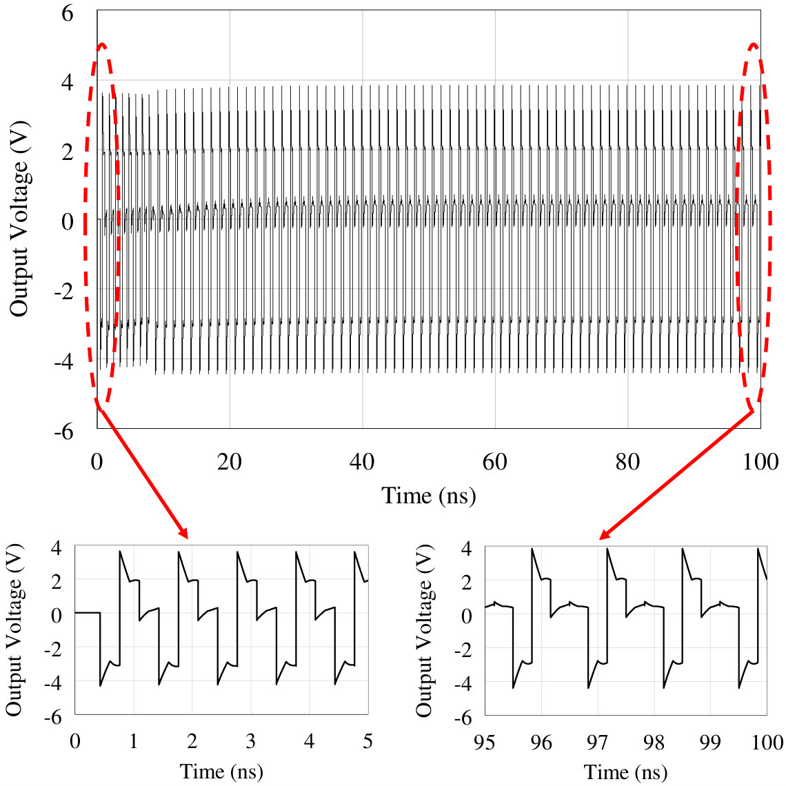 Figure 10
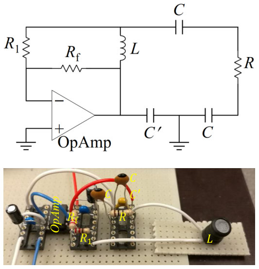 Figure 11
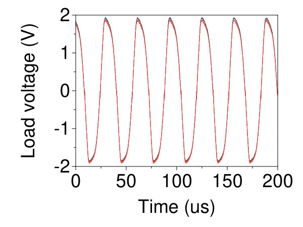 Figure 11
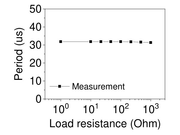 Figure 12
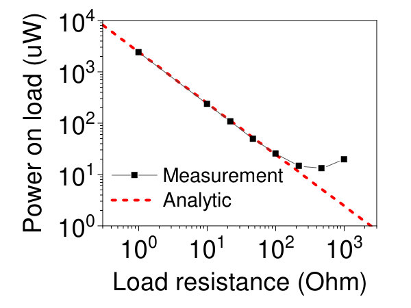 Figure 12
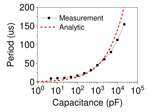 Figure 13
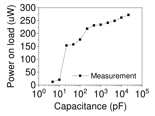 Figure 13
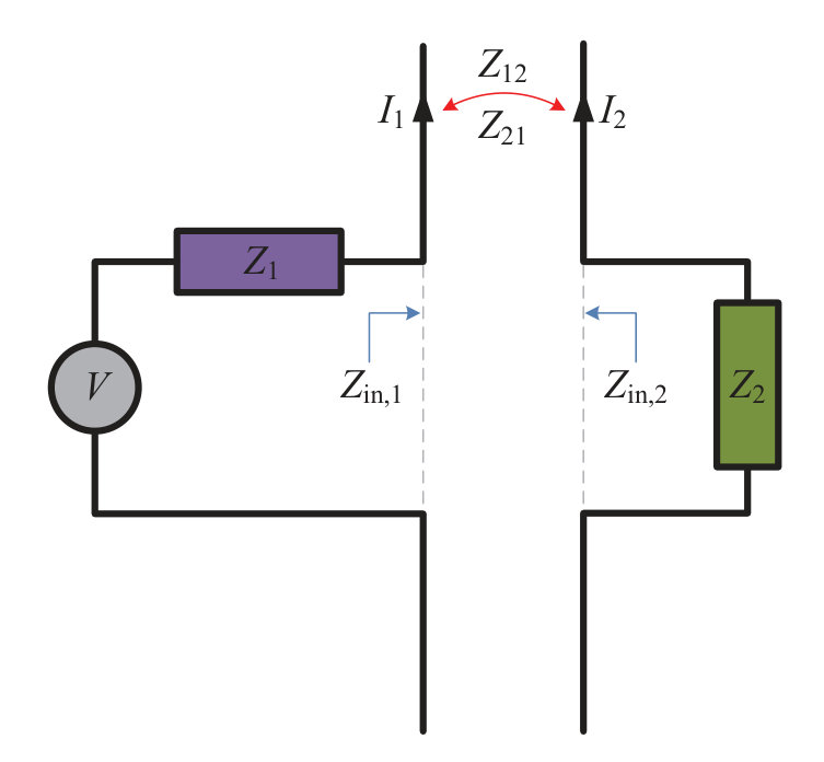 Figure 1
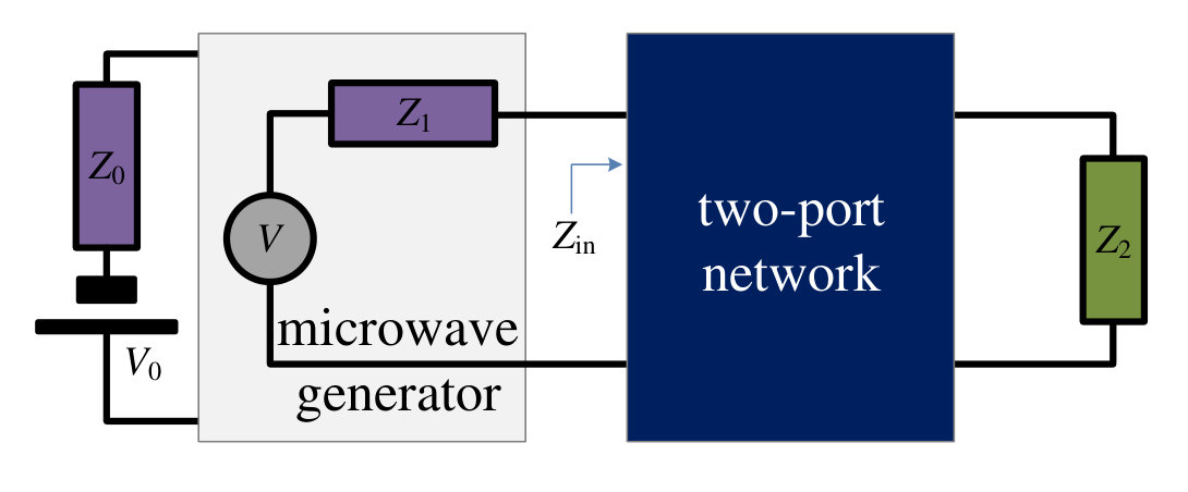 Figure 1
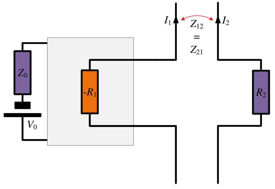 Figure 2
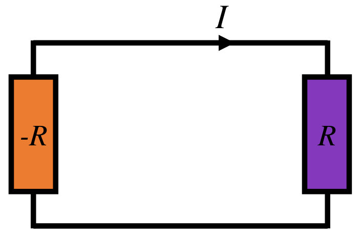 Figure 2
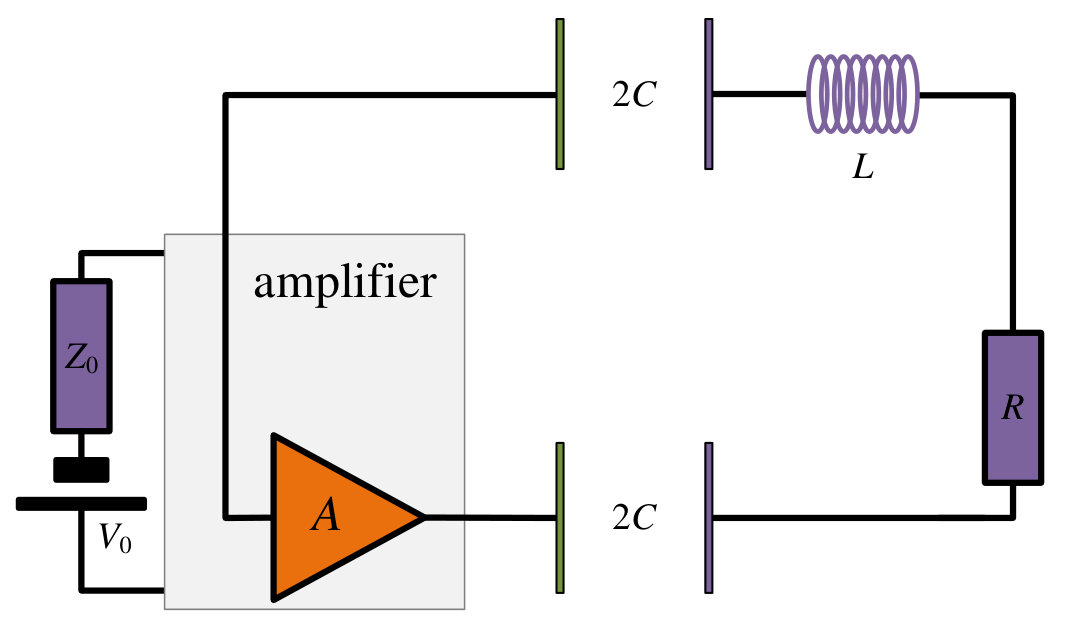 Figure 3
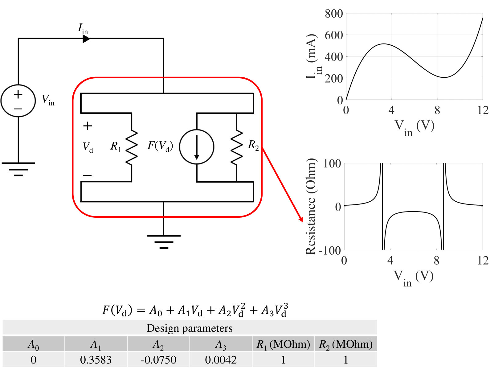 Figure 4
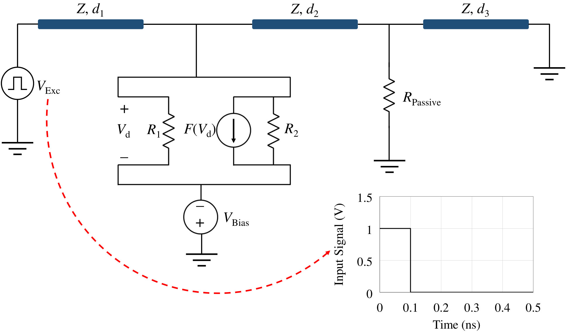 Figure 5
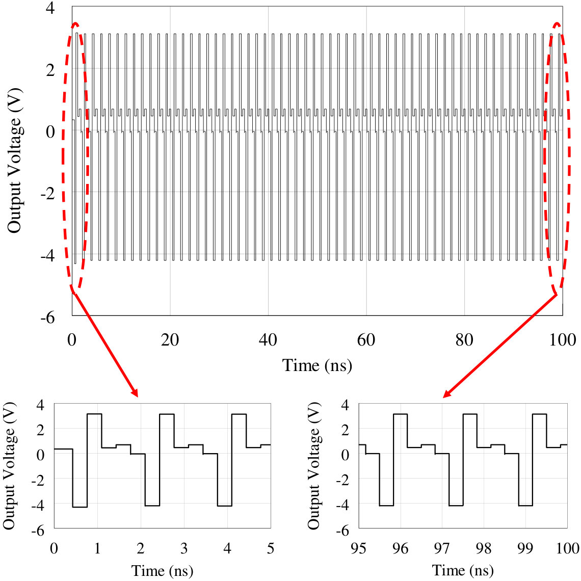 Figure 6
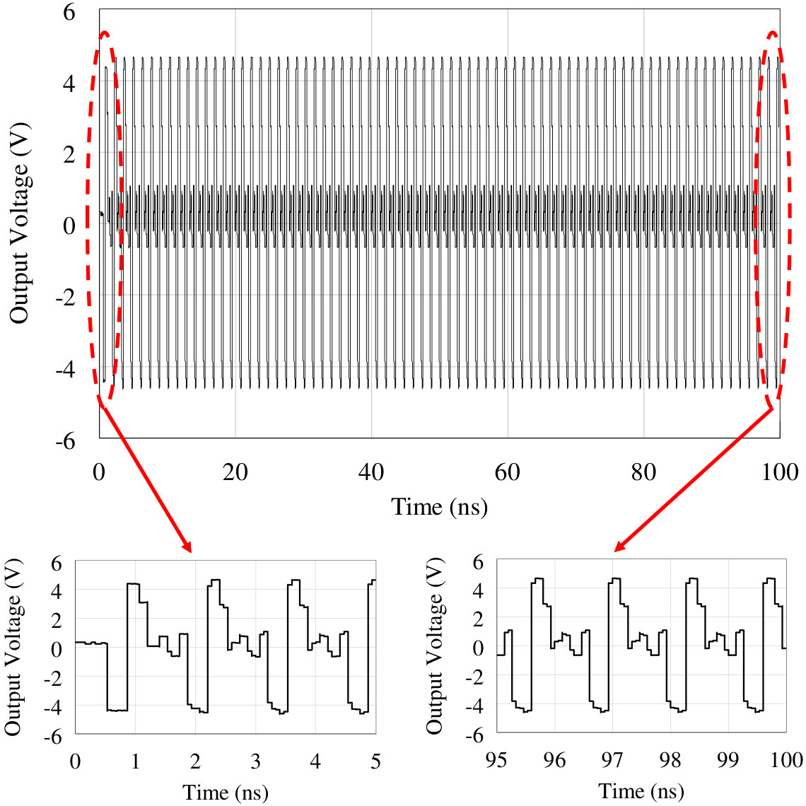 Figure 7
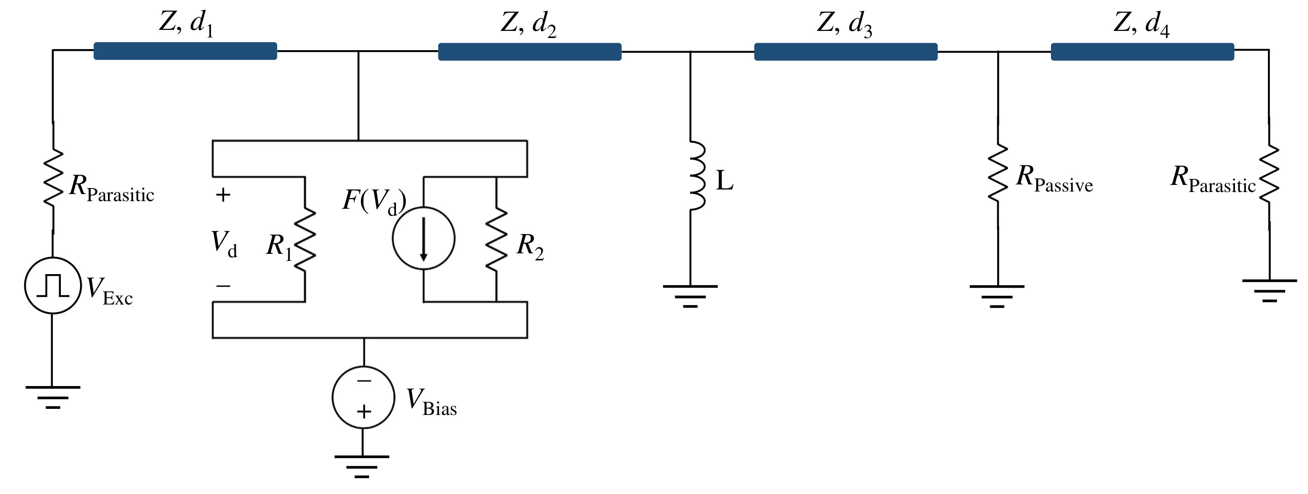 Figure 8
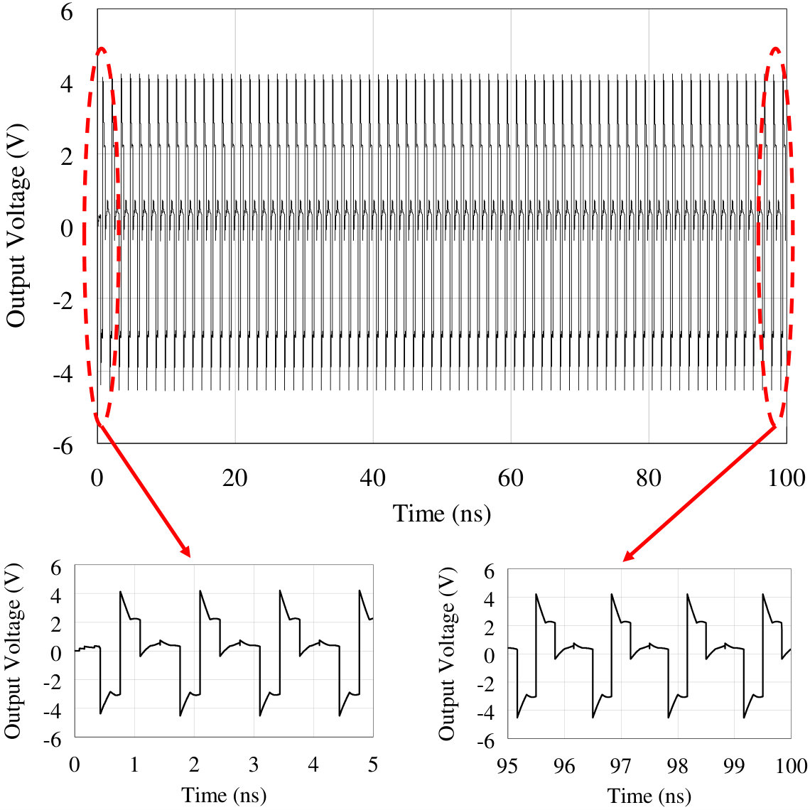 Figure 9
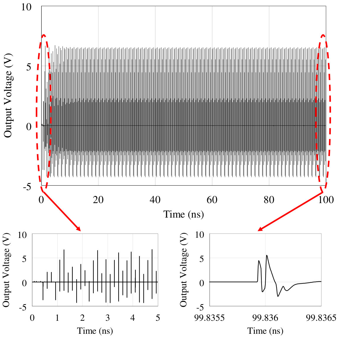 Figure 9
Peer Reviews
No public reviews on file for this paper yet. If you reviewed it on a platform where reviews are public (OpenReview, ICLR, NeurIPS, ICML), you can paste yours below so the community can read it here.
Videos
No videos yet. Explain this paper in a talk, walkthrough, or lecture? Add one.
On-Site Wireless Power Generation
Y. Ra’di, B. Chowkwale, C. A. Valagiannopoulos, , F. Liu, A. Alù, , C. R. Simovski, and S. A. Tretyakov Y. Ra’di and A. Alù are with the Department of Electrical and Computer Engineering, University of Texas at Austin, Austin, TX 78712 USA (e-mail: [email protected]). A. Alù is also with the Advanced Science Research Center, City University of New York, New York, NY 10031, USA. C.A. Valagiannopoulos is with the Department of Physics, School of Science and Technology, Nazarbayev University, Astana, KZ-010000, Kazakhstan. B. Chowkwale, F. Liu, C. R. Simovski, and S. A. Tretyakov are with the Department of Electronics and Nanoengineering, School of Electrical Engineering, Aalto University, P. O. Box 15500, FI-00076 Aalto, Finland.
Abstract
Conventional wireless power transfer systems consist of a microwave power generator and a microwave power receiver separated by some distance. To realize efficient power transfer, the system is typically brought to resonance, and the coupled-antenna mode is optimized to reduce radiation into the surrounding space. In this scheme, any modification of the receiver position or of its electromagnetic properties results in the necessity of dynamically tuning the whole system to restore the resonant matching condition. It implies poor robustness to the receiver location and load impedance, as well as additional energy consumption in the control network. In this study, we introduce a new paradigm for wireless power delivery based on which the whole system, including transmitter and receiver and the space in between, forms a unified microwave power generator. In our proposed scenario the load itself becomes part of the generator. Microwave oscillations are created directly at the receiver location, eliminating the need for dynamical tuning of the system within the range of the self-oscillation regime. The proposed concept has relevant connections with the recent interest in parity-time symmetric systems, in which balanced loss and gain distributions enable unusual electromagnetic responses.
Index Terms:
Wireless power transfer, parity-time symmetry reflection, transmission, resonance.
I Introduction
The practical importance of wireless power transfer (WPT) systems has been obvious since the time of N. Tesla, and recent advances in this field (see e.g. [1, 2, 3, 4, 5]), accompanied by the exponential growth in the request for fast and efficient wireless charging of battery-powered devices, has made these systems especially topical. In conventional WPT systems, the first stage of wireless power transport from the source to the load is a microwave generator, which transforms DC or 50/60 Hz power into microwave oscillations. This power transformation is necessary because wireless power links can operate efficiently only at reasonably high frequencies [1, 2, 3, 5]. Next, the microwave power available from this generator is sent into space using some kind of antenna. This energy is received by another antenna at the receiving end, and finally converted back to the DC or 50/60 Hz form and used there.
This conventional paradigm is illustrated in Fig. 1. In order to minimize power losses, the equivalent two-port network of the antennas and the free-space link between them should be reactive, which means that the antennas should be made of perfect conductors or other lossless materials, and the currents flowing on the antenna pair should form a non-radiating current distribution [6, 7], which is typically achieved operating in the very near field. In this way, radiation into free space is suppressed which, in the antenna engineering terminology [8], is translated into nullifying the total radiation resistance of the antenna system. This nullifying is achieved by optimizing the geometry and positions of the two antennas [9, 10].
The overall efficiency of this power transfer is limited by the internal resistance of the generator \mathop{\mathrm{missing}}{Re}\nolimits(Z_{1}), which constitutes an inevitable factor of power loss. In this conventional paradigm for WPT, there are actually two parasitic internal resistances where energy is lost, because the generator in Fig. 1 is fed by a DC source or from the mains, which are also not ideal voltage sources and therefore contain some non-zero internal resistance \mathop{\mathrm{missing}}{Re}\nolimits(Z_{0}).
Two scenarios of power transfer optimization are usually considered. In one of them, the system is tuned to maximize efficiency, minimizing power absorption in all parts of the system except at the receiver load. To this end, all resistors except the load resistor at the receiving end must be made as small as possible, including the internal resistance of the generator. In this scenario, the power efficiency can be large, however, the power output is not maximized, and the power extracted from the DC or 50/60 Hz supply and transferred to the load is relatively low. In the second scenario, the system is tuned to maximize the power transfer into the receiver load, which requires conjugate matching of the load to the source. In this case, half of the power is lost in the internal resistance of the source and the other half, in the ideal case, is delivered to the load. Therefore, even in the case of the ideal lossless coupling (e.g. via ideally conducting coils on a common lossless magnetic core of negligible electrical size) when the overall WPT efficiency in its traditional definition [5] is equal 100% the overall efficiency of the system cannot exceed 50%.
In both scenarios, maximization of delivered power requires mutual compensation of the reactive parts of the source, of the connecting two-port network, and of the load impedances, i.e., operating at resonance. Tuning the power transfer system to resonance as the load positions, environment, and impedance values vary requires complex control systems [11, 12, 13]. Besides the complexity, and, therefore, reduced reliability, the power consumed in these systems decreases the overall WPT efficiency.
In this paper, we introduce a different paradigm for wireless power transfer, in which the entire WPT system, including two antennas and the free-space link, forms a unified microwave generator. In this proposed scenario the load becomes an essential part of a microwave self-oscillating system. The optimal resonant regime is realized automatically as in a self-oscillating circuit. If we move or vary the receiving part of the system, the microwave frequency at which the self-oscillations are established automatically shifts, and no external tuning is actually needed. Since the intermediate step of converting DC or 50/60 Hz power into microwave oscillations is not needed, there is no parasitic resistance at the transmitting end, meaning that one of the two parasitic loss resistances is effectively eliminated. This inherent resilience is rooted in the suitable balance between loss and gain characterizing the system, and it is consistent with recent work in the area of parity-time symmetric systems [14, 15].
II Self-Oscillating Wireless Power Transfer Systems
The self-oscillating wireless power transfer concept that we introduce here can be understood after considering the equivalent circuit of a conventional wireless transfer system, illustrated in Fig. 1. A basic circuit analysis shows that the currents induced on the two antennas satisfy the linear system
[TABLE]
[TABLE]
Assuming that the mutual coupling is reciprocal, we can denote . Here the minus sign corresponds to the definition of the positive direction for currents as in Fig. 1. The current at the load reads
[TABLE]
and the power delivered to the load is equal to . The delivered power is maximized when the imaginary part of the denominator is zero, which corresponds to the resonance of the circuit. Furthermore, the real part of the mutual impedance (mutual resistance) should be made as large as possible in order to minimize the real part of the denominator and increase the numerator. By increasing the real part of the mutual impedance, we compensate the radiation resistance of the two antennas (the real parts of ) and, accordingly, we minimize the parasitic radiation into surrounding space. In the ideal limiting case (not realizable except the case of an ideal transformer mentioned in the introduction), which corresponds to the non-radiating condition for the coupled antenna system, i.e., when , all the power radiated by the generator antenna 1 is received by antenna 2, and the delivered power at resonance is limited only by the resistances of the source and the load.
We propose instead a wireless power delivery system that forms a self-oscillatory system in which microwave power is directly generated at the load, eliminating the limitation due to the source internal resistance . Considering the same conceptual equivalent scheme in Fig. 1, this regime can be realized if we assume that the internal resistance of the first circuit can be actually negative and that there is no voltage source, as illustrated in Fig. 2. In this case, the denominator of Eq. (3) can be made identically equal to zero, which implies that the current amplitude in the load is limited only by the non-linear properties of the negative resistor.
The necessary conditions for the existence of self-oscillations can be found equating the determinant of the system (1)–(2) to zero (with ). Let us assume for simplicity that the two antennas are identical and denote their input impedances by
[TABLE]
We write the results for real values of the two impedances and , (the reactances can be incorporated into and ). Denoting and equating the imaginary part of the determinant to zero, we get
[TABLE]
Minimization of radiation into free space corresponds to the situation when the mutual resistance nearly compensates the antenna radiation resistance, that is, (note that cannot be larger than since the antennas are passive). In this case equation (5) simplifies into
[TABLE]
Equating the real part of the determinant to zero gives
[TABLE]
Obviously, there are solutions with . At resonance, , the self-oscillation regime corresponds to
[TABLE]
In this system, there is only one power transformation from the primary power source (DC or mains) to microwave frequency oscillations. If the load practically needs to be fed by a DC or 50/60 Hz voltage, the backward transformation from the microwave range is, of course, necessary. However, it is not a necessary condition for a WPT system. The only unavoidable parasitic loss is in the inevitably nonzero internal resistance of the battery or of the main power supply, used to create negative resistance. Moreover, there is no need to manually or electronically tune the system to resonance, optimizing delivered power. The self-oscillating system generates microwave power in the load at the frequency or frequencies dictated by Eq. (8). If the load or antenna reactance varies, due to changes in the environment or in the location of the load, the frequency of self-oscillations will be modified accordingly. For the purpose of power transfer, such a change in the frequency is irrelevant: the delivered power is defined by the oscillations amplitude, which is mainly determined by the nonlinearity of the negative resistor and is weakly affected by the frequency change. In the ideal case, the schematic in Fig. 2 can be simplified to the one in Fig. 2. It is interesting to note that the system shown in Fig. 2 is indeed parity-time symmetric, and this property of resilience is similar to recent works focusing on parity-time symmetric systems [14, 15].
Although the above explanation is based on the use of negative-resistance circuits, the same proposed principle can be realized using other self-oscillating circuits. For example, consider a generator formed by a microwave amplifier with an appropriate positive feedback network. In this alternative scenario the wireless link can be a part of the feedback circuit of a generator, which creates microwave radiation directly where the power is needed. In other words, we include the near-field wireless link as an integral part of the microwave amplifier, and generate the microwave oscillations directly at the receiver. Depending on the operational frequency, this feedback channel can be for instance in the form of a waveguide or a coaxial cable or a microwave transmission line. Conceptually, to convert such a conventional generator into a wireless power delivery system, one can let a part of the feedback signal propagate in space, and position the power-receiving object into the field of the feedback wave.
As a particular example, consider a radio-frequency generator, where the positive feedback signal goes through a metal wire. Let us cut this feedback wire and connect the two ends to two metal plates, positioning them on the same plane one next to the other. Since the impedance between the two plates is large, the feedback loop is effectively disconnected, and there are no oscillations. Thus, in this regime, very little energy is consumed from the power source that feeds the amplifier on stand-by. To deliver energy to a resistive load, we equip the receiving device with other two metal plates of an appropriate size. If we now position this receiver on top of the two metal plates of the feedback circuit, at the frequency where the receiver plates, receiver connecting wires, and the feedback plates are in series resonance, the feedback loop closes and the self-oscillating system generates oscillations. Nearly all generated power is dissipated in the receiver only, if we use a high-efficiency amplifier.
This version of the proposed concept is illustrated in Fig. 3. Note that the only parasitic resistances are the loss resistances of the amplifier and the internal resistance of the primary power source which feeds the amplifier. The internal resistance of the microwave generator [resistor in the previous discussion] has been eliminated. If the reactances or the load impedance change within a reasonable range, so that the series resonance of the circuit falls within the frequency range where the amplifiers can operate, the same power will be delivered, even if the oscillation frequency changes.
III Numerical Demonstration of Wireless Power Generation
As a proof of concept demonstration of the potential of self-oscillating wireless power delivery, we consider a conceptually simple, one-dimensional numerical model. The active element is a non-linear negative resistor, realized as a voltage-controlled current source (see Fig. 4.) The non-linear dependence of the current on the voltage is modeled by a third-order polynomial, with coefficients given in Fig. 4. The same picture shows the corresponding volt-ampere curve and the associated differential resistance.
Free-space propagation between the active element and the load , sustained by two antennas, is modeled by a transmission line of length and characteristic impedance (see Fig. 5). In this circuit, pulse serves as the ignition that initiates self-oscillations in the circuit and dies out in less than ns (see subset in Fig. 5). This initial push source models thermal noise in conventional negative-resistor oscillators, which is present at any frequency. In order to model the non-radiating mode of the two antennas of the wireless power transfer system we terminate the transmission line by short circuits at both ends. In this ideal case, there is no parasitic radiation into space. Obviously, this model is appropriate also for wireless power transfer between two objects inside a shielded room, or in the near-field of each other. Note that the characteristic impedance of the transmission line here can be arbitrary. As a proof of concept example, here we assume the characteristic impedance of the transmission line to be Ohm. It should be noted that the proposed concept is perfectly applicable for more general scenarios where this impedance may be different depending on the particular realization. Note that for different scenarios the non-linear resistance is determined through equation (8).
The bias voltage of the negative-resistor subcircuit () should be chosen properly so that the non-linear subcircuit provides the required differential negative resistance and consequently the oscillations in the circuit can be initiated and continue after the push signal dies out. It can be seen from Fig. 4 that the differential resistance of the negative-resistor subcircuit depends on the applied bias voltage . Let us set the bias voltage of the subcircuit to V. As it can be seen from Fig. 4, such a choice fixes the operational point of the subcircuit in the negative-resistance region. At this point, the differential resistance of the subcircuit is about Ohm which, in the absolute value, is a bit higher than the resistance of the passive sheet ( Ohm in our example). Figure 6 shows the output voltage, that is, the voltage at the passive load. It is seen that the system is self-sustained after the push signal dies out, meaning that the negative resistor continues to deliver power to the passive load via the free-space propagation channel modeled by the transmission line.
The result of Fig. 6 corresponds to the ideal scenario where the two antennas form an ideal transmission channel, without any parasitic radiation into space, and when there is no unwanted dissipation. Recently, a few studies have shown that the operation of the conventional WPT systems can be dramatically affected by perturbations in their environment [9, 16]. Thus, it is important to study the influence of the load positions, parasitic losses and energy leakage to free space. Let us first demonstrate that the proposed design is robust with respect to changes of the distance between the active element and the passive load. As an example, Fig. 7 shows the results for the case where the distance between the loads is increased. The results confirm that the oscillations continue in the circuit despite the change in distance, delivering power from the active element to the passive one. As expected, the frequency spectrum of the output signal changes, but the self-oscillation power delivery regime is very stable.
Next, we study the effects of presence of reflecting obstacles in between the source and the load. In the one-dimensional transmission-line model this corresponds to a reactive element, inductance , inserted into the transmission-line path between the active element and the load (see Fig. 8). In the plane-wave propagation scenario, such an inductive obstacle corresponds to a metal wire mesh or a metal screen perforated with electrically small holes, which strongly reflect the waves back to the source. In the same figure, we show parasitic resistors that model parasitic radiation into surrounding space and dissipation losses. Figure 9 shows the results for the case in which an inductive element is located between the active and passive elements (here, ). The structure is still able to deliver power from the active load to the passive one. Considering an even more extreme scenario, Fig. 9 shows the results for a highly reflective inductive element with inductance pH located in between the active and passive impedances. For plane waves in free-space, this inductive element is equivalent to an ideally conducting sheet perforated with circular holes of mm diameter and period mm, provided that the wavelength is considerably larger than the period. Results in Fig. 9 show that, although the inductive element reflects almost (numerical estimation at 10 GHz) of the impinging wave, the system will still establish and continue self-oscillations, self-tuning itself during the transient to the optimal condition for power delivery. Note that even in this extreme scenario, the amplitude of voltage oscillations in the load is not significantly affected.
Figures 7 and 9 demonstrate that if the radiation into the surrounding space is suppressed, the proposed self-oscillating power delivery system is extremely robust with respect to positions of the receiver and insensitive to the presence of obstacles between the transmitting and receiving antennas. This feature resembles the effect of “teleportation” of waves through nearly perfectly reflective walls, recently proposed in [15].
Finally, we study the detrimental effects of parasitic radiation and dissipation in the system. The results of Fig. 10 show the voltage oscillations in the load resistor when the perfectly conducting boundaries at the two ends of the propagation channel model are replaced by resistors ( Ohm in this example). We see that degradation of the voltage amplitude in the load is rather small. The presence of the parasitic loss resistor has stronger effect on the shape of the pulses (the frequency spectrum) than on the amplitude of the voltage oscillations in the load.
IV Experimental Demonstration of a Self-oscillating Wireless Power Transfer System
In the preceding sections we have shown that self-oscillating circuits (comprising microwave power generators) can be used as wireless power transfer devices if the positive feedback loop passes energy through space to the load. There exists a great variety of generators and most of them can be appropriately modified for the wireless transfer use. It is clear that different types of self-oscillating circuits will offer different advantages and the choice of a particular realization will depend on the application requirements. For example, the structure shown in Fig. 2 offers extremely good stability with respect to the position of the receiver and the presence of obstacles (as discussed above); however, it is difficult to realize high overall efficiency, because creation of negative resistance usually requires driving significant current through an Ohmic resistor (for example, in impedance inverter circuits). On the other hand, for the topology shown in Fig. 3, both the overall efficiency and stability with respect to the receiver position can be very good, but changes of the value of the load resistor will modify the self-oscillation regime. To make the study more complete and demonstrate the versatility of the proposed paradigm, for an experimental demonstration we have selected an alternative topology of self-oscillating systems which is immune to changes of the load impedance, while the delivered power somewhat changes when the transfer distance changes.
The circuit which we study is a modified basic oscillating circuit based on an operational amplifier (we use an LM7171 amplifier from Texas Instruments). The schematic and the photo of the analyzed, constructed, and tested circuit are shown in Fig. 11. In this design, the two capacitors model the wireless channel (when they are replaced by metal plate pairs) through which the power is transferred to the load. For a simple demonstration, we used lumped elements with values MOhm, Ohm, mH, and nF. In the following, we study the oscillation period and the power consumption by the load with different load resistances and capacitances (modeling possibly varying loads and wireless transfer distances). The black and red curves in Fig. 11 (values close to each other) show the voltages at the two ends of the load when Ohm and pF (modeling power transfer between two metal plates with dimensions of 50 cm50 cm and separation of mm). We can see that quasi-sinusoidal oscillations are created at the load and the oscillation period is s. Moreover, knowing the voltage drop across the load, we can calculate the averaged power consumption by the load by calculating , which gives 2.4 mW. However, the overall efficiency is low, as the total power supplied from the DC source equals 375 mW. There are two main reasons for this high power consumption in the circuit. One is the chosen operational amplifier, which consumes a significant amount of energy. The other reason is the chosen topology of the self-oscillating circuit in which the capacitor directly connects the output of the amplifier to the ground. As the output is an oscillating wave, there is a non-negligible AC current passing through to the ground, leading to high power loss in the output resistance of the amplifier. We note that the power consumption by the other lumped elements (, , and ) is very low compared to the load resistance. Therefore, the overall efficiency of the WPT system based on self-oscillating circuit can be improved by using a better amplifier and alternative topologies of self-oscillating circuits.
Next, we perform the same measurements for different load resistances while keeping pF (modeling a fixed distance to the load). The measured oscillation period and power consumption for different are shown in Fig. 12. It is clear that the period exhibits remarkable stability with respect to which admits operation at a fixed frequency with a changing load. We see that the wireless system creates a virtual near-ideal voltage source at the load position, and the power consumption at the load decreases as when Ohm simply because the oscillating voltage across is almost unchanged. When Ohm, the electromotive force at the load increases. The red dashed curve in Fig. 12 is the plot of with mV, showing that the WPT system indeed realizes a nearly ideal voltage source at the load position, for load resistances smaller than Ohm.
Finally, we study the power transfer when we vary the capacitance value , corresponding to changes of the transfer distance in actual WPT implementations. In this case, we keep the load resistance constant at Ohm and change the capacitance values from 4.7 pF to 22 nF (i.e., corresponding to change of the wireless transfer distance from 0.471 m to 0.1 mm for capacitors realized based on metal plates with area cm2). The experimental results are shown in Fig. 13. As we observe, the oscillation period increases when we increase . Actually, the self-oscillation period can be obtained by analyzing the tank circuit, which gives . This analytical period is plotted as the red dashed curve in Fig. 13, explaining the experimental results. On the other hand, the power delivered to the load increases as the capacitance gets larger (corresponding to decreasing distance to the load). It is due to the fact that a larger capacitance supports more charge accumulation inside the capacitor leading to a higher voltage drop across the load. The aforementioned results clearly show that this version of the proposed self-oscillating wireless transfer wireless systems is very efficient and extremely robust against changes of the receiver resistance while the delivered power changes with the transfer distance. We remind that the topology depicted on Fig. 3 offers complementary properties, if those are preferable in the thought application.
V Conclusion
In conclusion, we have presented an alternative paradigm of wireless power transfer, where the transformation of DC or mains energy into microwave oscillations is integrated with the wireless power delivery. Microwave energy is generated directly at the location where it is needed, although the primary power source is at a different location. Both conventional and proposed systems contain a microwave generator, which inevitably consumes some energy. But, the proposed solution contains only a generator, while conventional systems contain additional elements which also have their own parasitic losses (and the output impedance of the generator is inevitably one of these parasitic resistances). Realizing power conversion from DC to oscillations and power transfer through space in one self-oscillating device offers possibilities for improvements of the overall efficiency, not available within conventional paradigms. Moreover, this new approach allows one to avoid the need of active control feedback loops that retune conventional WPT systems to the resonance when the environment of mutual locations of the transmitting and receiving circuits change. As a result, the robustness of the power transfer improves drastically. In the proposed designs, the system steady state is self-established in an automatic way due to the non-linear properties of the active element (an amplifier or a negative resistor). The wireless link is a part of the feedback loop of a microwave self-oscillating circuit and the whole system is a single microwave generator. In this paper we have numerically and experimentally demonstrated three different versions of self-oscillating WPT systems. We have compared the advantages and limitations of the test versions.
As a figure of merit, the conventional definition of the efficiency of WPT systems (the ratio of the power delivered to the load to the power transmitted by the source antenna) loses its meaning completely, because microwave power is created directly at the load. For this reason, we define the efficiency as the ratio of the power delivered to the load to the power drawn from the DC source (or mains). This overall system efficiency properly takes into account all power losses: in the active element, coupling elements, and due to parasitic radiation. In the realizations based on negative resistors (similar to PT-symmetric systems), there are parasitic losses in the active element, because in order to create negative resistance, bias current must flow through usual resistive elements. On the other hand, the feed-back scenario shown in Fig. 3 is free from this limitation. With the use of high-efficiency amplifiers, there are no inevitable parasitic resistances except the internal resistance of the primary source (a DC battery, for example). Thus, we expect that the system efficiency of the WPT systems based on the proposed concept is inherently higher than their conventional counterparts.
We believe that these results open new possibilities for the realization of simple, robust and effective wireless power transfer systems, and highlight a practically relevant application of self-oscillating circuits and balanced distributions of loss and gain for electromagnetics.
During the review process of this manuscript, after our submission, Ref. [19] was published, which independently from this work introduced a WPT scenario based on a combination of negative and positive resistors (similar to PT-symmetric structures), as a way to limit the sensitivity of WPT systems to variations in distance between source and receiver. As explained here, this is a special case of self-oscillating WPT systems, which we introduce here.
Acknowledgment
This project has received partial funding from the European Union’s Horizon 2020 research and innovation programme-Future Emerging Topics (FETOPEN) under grant agreement No 736876. Funding from NU ORAU Grant No. 20162031 and MES RK state-targeted program BR05236454 is also acknowledged.
The reference list from the paper itself. Each links out to its DOI / PubMed record.
- 1[1] A. Kurs, A. Karalis, R. Moffatt, J. D. Joannopoulos, P. Fisher, M. Soljačić, “Wireless power transfer via strongly coupled magnetic resonances,” Science, vol. 317, no. 5834, pp. 83–86, 2007.
- 2[2] S. Y. R. Hui, W. Zhong, and C. K. Lee, “A critical review of recent progress in mid-range wireless power transfer,” IEEE Trans. Power Electr., vol. 29, no. 9, pp. 4500–4511, 2014.
- 3[3] J. Lee and S. Nam, “Fundamental aspects of near-field coupling small antennas for wireless power transfer,” IEEE Trans. Antennas Propag., vol. 58, no. 11, pp. 3442–3449, 2010.
- 4[4] Q. Chen, K. Ozawa, Q. Yuan, and K. Sawaya, Antenna characterization for wireless power-transmission system using near-field coupling, IEEE Antennas and Propagation Magazine, vol.54, no.4, pp.108-116, 2012.
- 5[5] K. Y. Kim, Wireless Power Transfer–Principles and Engineering Explorations, New York, NY, USA: In Tech, 2012.
- 6[6] A. J. Devaney and E. Wolf, “Radiating and nonradiating classical current distributions and the fields they generate,” Phys. Rev. D, vol. 8, no. 4, pp. 1044–1047, 1973.
- 7[7] I. Lindell, Methods for Electromagnetic Field Analysis, Oxford, UK: Clarendon Press, 1992 (Section 6.1).
- 8[8] C. Balanis, Antenna Theory: Analysis and Design, New York–Brisbane, NY, USA: J. Wiley, 1982.