Identifying combinations of tetrahedra into hexahedra: a vertex based strategy
Jeanne Pellerin, Amaury Johnen, Kilian Verhetsel, Jean-Francois, Remacle
TL;DR
This paper presents a vertex-based algorithm for efficiently identifying all possible hexahedra, prisms, and pyramids within a tetrahedral mesh, significantly improving detection speed and coverage for engineering analysis.
Contribution
The authors introduce a novel vertex-based method that rapidly detects all valid combinations of tetrahedra forming complex polyhedral cells, surpassing pattern-based approaches.
Findings
Identifies over 3 million potential hexahedra in 10 seconds on a laptop.
Builds a larger set of potential hexes than predefined subdivision patterns.
Early quality checks improve efficiency by discarding poor-quality cells.
Abstract
Indirect hex-dominant meshing methods rely on the detection of adjacent tetrahedra an algorithm that performs this identification and builds the set of all possible combinations of tetrahedral elements of an input mesh T into hexahedra, prisms, or pyramids. All identified cells are valid for engineering analysis. First, all combinations of eight/six/five vertices whose connectivity in T matches the connectivity of a hexahedron/prism/pyramid are computed. The subset of tetrahedra of T triangulating each potential cell is then determined. Quality checks allow to early discard poor quality cells and to dramatically improve the efficiency of the method. Each potential hexahedron/prism/pyramid is computed only once. Around 3 millions potential hexahedra are computed in 10 seconds on a laptop. We finally demonstrate that the set of potential hexes built by our algorithm is significantly…
| 1234 | 1243 | 1324 | 1342 | 1423 | 1432 |
| 2134 | 2143 | 2314 | 2341 | 2413 | 2431 |
| 3124 | 3142 | 3214 | 3241 | 3412 | 3421 |
| 4123 | 4132 | 4213 | 4231 | 4312 | 4321 |
| 1234 | 1243 | 1324 |
| Model | #vertices | #tets | #bd tris | Load (s) | Struct. (s) |
|---|---|---|---|---|---|
| Cube | 127 | 396 | 192 | 0.01 | 0.01 |
| Fusee | 11,975 | 50,750 | 15,128 | 0.07 | 0.04 |
| CrankShaft | 23,245 | 104,302 | 27,342 | 0.13 | 0.09 |
| Fusee_1 | 71,947 | 349,893 | 55,954 | 0.40 | 0.26 |
| Caliper | 130,572 | 675,289 | 79,446 | 0.77 | 0.49 |
| CrankShaft_2 | 140,985 | 763,870 | 59,656 | 0.87 | 0.52 |
| Fusee_2 | 161,888 | 828,723 | 98,952 | 0.95 | 0.58 |
| FT47_b | 221,780 | 1,260,255 | 55,178 | 1.42 | 0.83 |
| FT47 | 370,401 | 2,085,394 | 102,434 | 2.36 | 1.40 |
| Fusee_3 | 501,021 | 2,694,950 | 217,722 | 3.07 | 1.89 |
| Los1 | 583,561 | 3,250,705 | 182,814 | 3.76 | 2.28 |
| Knuckle | 3,058,481 | 17,466,833 | 640,081 | 17.49 | 16.25 |
| Cells | Timings (s) | Cells | Timings (s) | ||||||||||
|---|---|---|---|---|---|---|---|---|---|---|---|---|---|
| Qmin | #Hexes | #Prisms | #Pyr. | Hex | Pri. | Pyr. | Qmin | #Hexes | #Prisms | #Pyr. | Hex | Pri. | Pyr. |
| Cube | Fusee 2 | ||||||||||||
| 0 | 710 | 1,596 | 1,172 | 0.03 | 0.01 | 0.01 | 0 | 4,586,779 | 5,866,663 | 3,122,057 | 9.46 | 6.88 | 1.21 |
| 0.2 | 349 | 1,052 | 661 | 0.01 | 0.01 | 0.01 | 0.2 | 3,147,148 | 4,614,298 | 2,013,799 | 6.17 | 5.37 | 0.92 |
| 0.4 | 308 | 1,010 | 639 | 0.01 | 0.01 | 0.01 | 0.4 | 1,940,213 | 3,978,611 | 1,746,731 | 4.13 | 4.79 | 0.85 |
| 0.6 | 129 | 661 | 615 | 0.01 | 0.01 | 0.01 | 0.6 | 455,155 | 1,849,333 | 1,489,604 | 1.27 | 2.44 | 0.78 |
| 0.8 | 64 | 218 | 138 | 0.01 | 0.01 | 0.01 | 0.8 | 114,224 | 520,350 | 333,250 | 0.40 | 0.86 | 0.46 |
| Fusee | FT47_b | ||||||||||||
| 0 | 149,731 | 251,131 | 158,671 | 0.50 | 0.37 | 0.07 | 0 | 8,374,128 | 9,845,963 | 4,954,902 | 16.34 | 11.28 | 2.06 |
| 0.2 | 95,259 | 193,440 | 120,496 | 0.30 | 0.28 | 0.06 | 0.2 | 6,111,946 | 8,046,676 | 3,177,657 | 11.11 | 9.11 | 1.45 |
| 0.4 | 50,931 | 148,390 | 99,949 | 0.19 | 0.23 | 0.05 | 0.4 | 3,413,741 | 6,963,922 | 2,798,967 | 6.88 | 8.09 | 1.34 |
| 0.6 | 14,978 | 73,397 | 74,831 | 0.07 | 0.13 | 0.04 | 0.6 | 869,890 | 3,257,991 | 2,349,396 | 2.33 | 4.13 | 1.22 |
| 0.8 | 4,187 | 20,323 | 18,312 | 0.02 | 0.05 | 0.03 | 0.8 | 184,921 | 808,736 | 745,059 | 0.65 | 1.40 | 0.78 |
| CrankShaft | FT47 | ||||||||||||
| 0 | 309,938 | 516,217 | 327,071 | 1.06 | 0.78 | 0.14 | 0 | 13,842,934 | 15,994,194 | 8,098,013 | 26.79 | 19.32 | 3.42 |
| 0.2 | 196,441 | 400,698 | 255,842 | 0.65 | 0.60 | 0.12 | 0.2 | 10,225,710 | 13,177,806 | 4,968,253 | 18.28 | 14.90 | 2.33 |
| 0.4 | 97,194 | 291,381 | 205,388 | 0.38 | 0.47 | 0.11 | 0.4 | 5,978,752 | 11,638,277 | 4,441,345 | 11.65 | 13.54 | 2.18 |
| 0.6 | 27,549 | 138,308 | 143,964 | 0.15 | 0.26 | 0.09 | 0.6 | 1,481,030 | 5,392,542 | 3,886,408 | 3.76 | 6.76 | 1.99 |
| 0.8 | 6,381 | 35,157 | 33,804 | 0.05 | 0.10 | 0.06 | 0.8 | 325,062 | 1,428,695 | 1,080,358 | 1.05 | 2.32 | 1.24 |
| Fusee 1 | Fusee 3 | ||||||||||||
| 0 | 1,692,873 | 2,323,521 | 1,283,513 | 3.90 | 2.85 | 0.52 | 0 | 17,052,534 | 20,251,770 | 10,377,769 | 33.06 | 24.08 | 4.43 |
| 0.2 | 1,098,993 | 1,792,440 | 866,043 | 2.40 | 2.17 | 0.40 | 0.2 | 12,581,618 | 16,270,311 | 6,218,061 | 22.75 | 18.75 | 2.94 |
| 0.4 | 655,375 | 1,496,380 | 739,789 | 1.58 | 1.88 | 0.37 | 0.4 | 8,214,177 | 14,639,094 | 5,562,577 | 15.55 | 16.63 | 2.75 |
| 0.6 | 167,752 | 714,225 | 610,352 | 0.53 | 0.99 | 0.33 | 0.6 | 1,770,306 | 6,701,699 | 4,969,021 | 4.41 | 8.39 | 2.59 |
| 0.8 | 46,215 | 207,852 | 139,521 | 0.17 | 0.36 | 0.21 | 0.8 | 414,528 | 1,859,542 | 1,047,155 | 1.34 | 2.92 | 1.54 |
| Caliper | Los1 | ||||||||||||
| 0 | 3,536,954 | 4,675,695 | 2,508,509 | 7.96 | 5.73 | 1.03 | 0 | 21,909,206 | 25,424,213 | 12,802,385 | 42.21 | 30.00 | 6.30 |
| 0.2 | 2,341,875 | 3,706,438 | 1,745,660 | 5.07 | 4.48 | 0.81 | 0.2 | 16,152,752 | 20,505,357 | 7,698,238 | 28.56 | 23.60 | 3.61 |
| 0.4 | 1,262,784 | 3,032,209 | 1,490,139 | 3.15 | 3.82 | 0.75 | 0.4 | 10,300,168 | 18,629,804 | 6,821,354 | 19.39 | 21.42 | 3.37 |
| 0.6 | 314,028 | 1,372,489 | 1,205,077 | 1.08 | 1.97 | 0.67 | 0.6 | 2,330,993 | 8,867,751 | 6,106,437 | 5.81 | 10.84 | 3.13 |
| 0.8 | 78,639 | 376,243 | 301,792 | 0.34 | 0.73 | 0.43 | 0.8 | 502,613 | 2,262,204 | 1,798,365 | 1.61 | 3.54 | 1.94 |
| Crankshaft 2 | Knuckle | ||||||||||||
| 0 | 4,406,357 | 5,565,490 | 2,898,887 | 9.24 | 6.45 | 1.24 | 0 | 86,688,872 | 122,469,704 | 64,495,784 | 220.75 | 161.08 | 28.29 |
| 0.2 | 2,983,490 | 4,376,413 | 1,874,339 | 5.84 | 5.11 | 0.86 | 0.2 | 51,459,040 | 93,888,327 | 36,416,856 | 132.79 | 122.33 | 19.81 |
| 0.4 | 1,683,753 | 3,777,653 | 1,598,601 | 3.63 | 4.41 | 0.78 | 0.4 | 34,537,750 | 87,271,830 | 34,099,717 | 96.46 | 115.21 | 19.37 |
| 0.6 | 417,004 | 1,677,332 | 1,385,062 | 1.20 | 2.21 | 0.72 | 0.6 | 9,499,091 | 42,600,754 | 32,019,383 | 31.59 | 62.31 | 18.77 |
| 0.8 | 104,728 | 468,154 | 301,721 | 0.36 | 0.79 | 0.43 | 0.8 | 2,837,726 | 10,931,917 | 6,650,518 | 9.44 | 20.43 | 11.32 |
| Model | Ours | [3] | [6, 7] | [4] |
|---|---|---|---|---|
| Cube | 710 | 672 | 696 | 706 |
| Fusee | 149,627 | 123,696 | 142,783 | 146,022 |
| CrankShaft | 310,181 | 251,806 | 294,182 | 302,131 |
| Fusee_1 | 1,692,188 | 1,532,747 | 1,683,543 | 1,686,709 |
| Caliper | 3,536,997 | 3,175,201 | 3,513,863 | 3,522,483 |
| CrankShaft_2 | 4,405,892 | 3,919,768 | 4,383,763 | 4,392,081 |
| Fusee_2 | 4,585,236 | 4,110,253 | 4,568,332 | 4,574,594 |
| FT47_b | 8,374,930 | 7,384,695 | 8,343,306 | 8,355,231 |
| FT47 | 13,846,837 | 12,133,218 | 13,806,781 | 13,821,507 |
| Fusee_3 | 17,048,021 | 14,983,008 | 17,010,173 | 17,023,768 |
| Los1 | 21,908,307 | 19,308,740 | 21,865,212 | 21,880,467 |
| Knuckle | 86,553,836 | 79,544,742 | 86,346,178 | 86,433,942 |
Peer Reviews
No public reviews on file for this paper yet. If you reviewed it on a platform where reviews are public (OpenReview, ICLR, NeurIPS, ICML), you can paste yours below so the community can read it here.
Videos
No videos yet. Explain this paper in a talk, walkthrough, or lecture? Add one.
Identifying combinations of tetrahedra into hexahedra: a vertex based strategy
Jeanne Pellerin
Amaury Johnen
Kilian Verhetsel
Jean-François Remacle
Université catholique de Louvain, iMMC, Avenue Georges Lemaitre 4, bte L4.05.02, 1348 Louvain-la-Neuve, Belgium
Abstract
Indirect hex-dominant meshing methods rely on the detection of adjacent tetrahedra that may be combined to form hexahedra, prisms and pyramids. In this paper we introduce an algorithm that performs this identification and builds the set of all possible combinations of tetrahedral elements of an input mesh into hexahedra, prisms, or pyramids. All identified cells are valid for engineering analysis. First, all combinations of eight/six/five vertices whose connectivity in matches the connectivity of a hexahedron/prism/pyramid are computed. The subset of tetrahedra of triangulating each potential cell is then determined. Quality checks allow to early discard poor quality cells and to dramatically improve the efficiency of the method. Each potential hexahedron/prism/pyramid is computed only once. Around 3 millions potential hexahedra are computed in 10 seconds on a laptop. We finally demonstrate that the set of potential hexes built by our algorithm is significantly larger than those built using predefined patterns of subdivision of a hexahedron in tetrahedral elements.
keywords:
Finite element; Hex-dominant mesh; Indirect meshing; Triangulation; Prism; Pyramid
1 Introduction
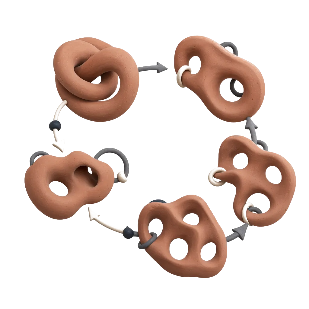
In this paper we propose a new algorithm to identify all the hexahedra that may be built by combining tetrahedra of a given mesh. Hexahedral meshes are considered by most of the finite element practitioners to be superior to tetrahedral meshes (see e.g. [1]). Yet, no robust meshing technique is able to process general 3D domains. And generating hexahedral meshes in an automatic manner is still considered as the ultimate goal in mesh generation [2]. Recently, promising techniques producing meshes composed of a majority of hexahedra have been proposed [3, 4, 5, 6, 7]. These methods take advantage of the existence of robust algorithms to generate tetrahedral meshes and combine tetrahedra to produce meshes composed of a majority of hexahedra associated to prisms, pyramids and tetrahedra . The four steps of these indirect hex-dominant meshing methods can be summarized as follows (see also Figure 1):
A set of mesh vertices is initially sampled in the domain. 2. 2.
A tetrahedral mesh is built by connecting , e.g. using a Delaunay kernel like [8]. 3. 3.
The set of potential cells (hexahedra, prisms, pyramids) that can be defined by combining tetrahedra of is built. 4. 4.
A maximal subset constituted of cells that can be part of the same final mesh is determined. The final hex-dominant mesh is obtained adding the remaining not selected tetrahedra .
To reach the ultimate goal and combine all tetrahedra into hexahedra, i.e. obtain a final full-hexahedral mesh, all steps are crucial. Previous works primarily focus on the first step of placing the final mesh vertices. In this paper, we focus on the third step. Our input is a tetrahedral mesh of a given point set and we output the set of all hexahedra, prisms, and pyramids that may be built by combining tetrahedra of .
Identifying combinations of tetrahedra into pyramids is trivial. There are three possible pyramids for each facet shared by two tetrahedra of . Identifying combinations of tetrahedra into prisms is a bit more challenging since three tetrahedra properly connected should be identified. However, when identifying combinations of tetrahedra into hexahedra, there are at least ten different subdivisions of a hexahedron into five, six, or seven tetrahedra (§2). To overcome this challenge, two main approaches have been proposed. The first relies on a predefined set of patterns of the decomposition of a hexahedron into tetrahedra [3, 6, 7], the second on patterns of edge connections in a hexahedron [4, 5]. Their main limitation is that they do not build the largest set of potential hexahedra . For example, they do not detect the two hexahedra of Figure 2 (more details in §2.4).
In this paper, we introduce an algorithm that detects all possible combinations of tetrahedra into hexahedra. The algorithm is based on the local search of combinations of eight vertices that are adequately connected to build a hexahedron. The key advantages of the new algorithm are that it computes all possible potential hexahedra, computes each of them once only, discards bad quality hexes at an early stage, is easy to implement and is very efficient. The algorithm does not rely on any pattern. An algorithm variation permits to compute all the possible potential prisms.
After reviewing the main methods to combine tetrahedra into hexahedra , prisms or pyramids (§2), we detail our vertex-based algorithm to identify the potential hexahedra , prisms and pyramids in a tetrahedral mesh (§3). We demonstrate we actually compute the set of all possible hexahedra , prisms, and pyramids. We further show in particular that the set of hexahedra built by our algorithm is larger than the one built by existing methods (§4.2). Examples of hex-dominant mesh that may be generated from these potential cells are given in §4.3. The C++ code implementing the methods of this paper is open-source and available at https://www.hextreme.eu/download/.
2 Background
Before giving details on subdivisions of hexahedra , prisms or pyramids into tetrahedra (§2.2) and on methods used to identify these in an existing mesh (§2.3), we define the terms and notations used throughout the paper.
2.1 Definitions
We have to be very clear that all the cells we are considering are finite element cells hexahedra /prisms/pyramids valid for finite element simulations. A very important point is that their quadrilateral facets are not planar, but are bilinear surfaces. We require the Jacobian determinant to be strictly positive at any point inside the cell. The following conventions will be used throughout this paper (see Figure 3).
The pyramid {abcde} has:
5 vertices: {a}, {b}, {c}, {d}, {e}
- 2.
8 straight line edges: {ab}, {bc}, {cd}, {ad}, {ae}, {be}, {ce}, {de}
- 3.
4 planar triangle faces: {abe}, {bce}, {cde}, {ade}
- 4.
1 bilinear quadrilateral face: {abcd}
The prism {abcdef} has:
6 vertices: {a}, {b}, {c}, {d}, {e}, {f}
- 2.
9 straight line edges: {ab}, {bc}, {ca}, {ad}, {be}, {cf}, {de}, {ef}, {fd}
- 3.
2 planar triangle faces: {abc}, {def}
- 4.
3 bilinear quadrilateral faces: {abed}, {efcb}, {acfd}
The hexahedron {abcdefgh} has:
8 vertices: {a}, {b}, {c}, {d}, {e}, {f}, {g}, {h},
- 2.
12 straight line edges: {ab}, {bc}, {cd}, {ad}, {ae}, {bf}, {cg}, {dh}, {ef}, {fg}, {gh}, {eh}
- 3.
6 bilinear quadrilateral faces: {abcd}, {efgh}, {abfe}, {dcgh}, {bcgf}, {adhe},
A triangulation (tetrahedrization) of a hexahedron/prism/pyramid is a triangulation of the vertices of the cell that respect the cell boundary, in other words it is a subdivision of the interior of the hexahedron/prism/pyramid into a set of conformal tetrahedra without any additional vertex. The tetrahedra induce a subdivision of each quadrilateral facet into two triangles by a diagonal boundary edge. We further define the boundary tetrahedra as the tetrahedra connecting the four vertices of a cell quadrilateral facet (Figure 4.2). In previous works [3, 6, 5, 7], boundary tetrahedra are called slivers. We do not use that term which refers to a geometrical property (degeneracy) of tetrahedra. The triangulation is determined by interior tetrahedra (Figure 4.1). Indeed, the addition or removal of one or several boundary tetrahedra does not modify the cell.
2.2 Decomposing a cell into tetrahedral elements
We first review the subdivisions of the pyramid, of the prism and of the 3-cube into tetrahedra [9].
Triangulation of the pyramid
There are as many subdivisions of the general pyramid as there are subdivisions of its planar base [9]. We are considering square pyramids, there are then exactly two triangulations of the pyramid.
Triangulation of the prism
The ordinary triangular prism is the result of the product of a triangle with an edge: prism. A prism() has exactly triangulations that are all equivalent to one another by affine symmetries [9]. The prism has then 6 triangulations that are all equivalent.
Triangulation of the 3-cube I
The 3-cube has exactly 74 triangulations [9] :
Every triangulation of the 3-cube contains either a regular tetrahedron (i.e. a tetrahedron whose 6 edges are of equal lengths) or a diameter, i.e. an interior edge joining two opposite vertices (red edges on Figure 5). 2. 2.
There are 2 triangulations with a regular tetrahedron, symmetric to one another. The triangulations containing an interior edge are completely classified modulo symmetries by their dual complex which can be one of the last five shown on Figure 5. There are respectively 8, 24, 12, 24, 4 triangulations in each class.
A dual complex (Figure 5) is a practical way to visualize the 6 different possible decompositions (tetrahedrizations) of the 3-cube. In the dual complex, also called dual graph, one vertex corresponds to one tetrahedron and two vertices are connected by an edge if the corresponding tetrahedra are adjacent through a triangular facet. A 2-cell of the dual complex (cycle in the dual graph) corresponds to an interior edge of the tetrahedrization (red on Figure 5). In a meshing context, these different possible decompositions of the 3-cube were identified by [3] who enumerate the feasible dual complex graphs, called RF-graph in their paper. In the RF-graph, additional dashed edges connect tetrahedra that are adjacent to the same quadrilateral facet (Figure 5).
Triangulations of the real cube
Recently, the work of [3] was extended by [6] and [7] who proposed four additional decomposition patterns into seven tetrahedra (Figure 6). The hexahedron is split into two prisms by a tetrahedron without any facet on the hexahedron boundary and containing two interior edges. For this tetrahedron to have a strictly positive volume, it is sufficient to work in finite precision, i.e. move slightly one of its vertices.
Bounds on the number of tetrahedra
The Euler characteristic gives a relationship between the number of tetrahedra in a cell decomposition and its number of interior edges . Each triangulation is a 3-ball with Euler characteristic , where . Then . Since there are 4 triangular faces per tetrahedron and 2 tetrahedra per interior triangular face, we have . Since the number of boundary edges , and boundary triangular facets are fixed for each type of cell, the number of tetrahedra in a hexahedron , prism or pyramid decomposition (without internal vertices) depends only on the number of interior edges . Moreover, there are at most edges in a cell with vertices we then have trivial bounds on the number of tetrahedra in the triangulation of the cells.
For the hexahedron: and .
- 2.
For the prism: and
- 3.
For the pyramid: and .
See also [10] for additional combinatorial results.
2.3 Combining tetrahedra into hexahedra: state of the art
To compute the set of potential hexahedra and other cells that may be built by combining the elements of a tetrahedral mesh without modifying its connectivity there are two known approaches. [3] propose to find combinations of tetrahedra into hexahedra by searching the adjacency graph of for all occurrences of the cube decomposition dual complexes (Figure 5). The problem of matching subgraphs in large sparse graphs is solved using standard data mining algorithms that operate on graphs. The same technique is used by [11, 12, 6] and [7] who consider four decompositions into seven tetrahedra (Figure 6). The second approach proposed by [4] relies on the vertices and edges of the tetrahedral mesh . Local searches are performed into the vertex-edge graph of using two patterns. These vertex connectivity patterns generalize those proposed by [3] and relax partially the dependency on the tetrahedral mesh. This method has been implemented by [5] where a third pattern taking into account configurations with an interior flat tetrahedron was added. Some other approaches like H-Morph [13] combine tetrahedra into hexahedra, while allowing for modifications of the connectivity and geometry of the input tetrahedral mesh (tetrahedron flips, node insertions, and node displacement). This great flexibility can make the algorithm intractable, but one advantage is that it maintains a valid mixed mesh throughout the procedure.
2.4 Motivations for a new approach
Important observations led us to work on improving these existing techniques. First, they do not identify the largest set of potential hexahedra. On Figure 2 we gave two valid hexahedra that would neither be found by [3]’s method nor by [4]’s method. The first is a decomposition that encompasses one internal vertex, a configuration that may occur when a Steiner point is added when generating the tetrahedra. The second is a decomposition that has 8 interior tetrahedra. It is a counter example to [7]’s claim that there is no hexahedron decomposition with more than 7 interior tetrahedra. Both decompositions are not identified when searching for hexahedra made of 5, 6, or 7 interior tetrahedra. Neither are they by [4]’s algorithm since none of their constitutive tetrahedra has three facets on the hexahedron boundary.
Second, as mentioned by [4], several hexahedra may be defined using the same decomposition pattern by modifying the ordering of the vertices (Figure 7). The hexahedra have different edges and different faces while having the same tetrahedral decomposition. The hexahedron on the left being a perfect cube, the one on the right is undoubtedly invalid (zero Jacobian determinant), but were the vertices in a more general position, both could be valid. Third, the existing methods identify the same hexahedron several times. That number is as high as the number of corner tetrahedra in the decomposition in [4]’s approach and depends on dual complex symmetries in [3]’s approach. With those observations in mind, we believe that an algorithm that finds all potential hexahedra in a tetrahedral mesh should not be based on a predefined set of patterns.
3 An algorithm to combine tetrahedra into hexahedra
In this section, we detail our algorithm to detect combinations of tetrahedra into hexahedra or prisms and find all cells that may be generated by combining elements of a given input tetrahedral mesh . We first explain the 2d version of the algorithm that combines triangles into quadrilaterals and show its relationship to algorithms generating permutations and combinations.
3.1 The 2D algorithm
The 2D version of the algorithm is built by modifying an algorithm generating the -permutations of a -set. Given a set of vertices labeled from to , let us first compute all possible quadrilaterals that can be defined from these vertices. We define a numbered quadrilateral by the order of its 4 vertices and we define a non-oriented quadrilateral by its edges and ignoring orientation. Generating all numbered quadrilaterals that can be built from is a combinatorial problem solved by Algorithm 1 which generates all possible permutations of 4 vertices of the labels. When , the output is the set of the 24 permutations of 4 values (Table 1). These 24 permutations define 3 different non-oriented quadrilaterals, each of them corresponding to 8 equivalent permutations. Adding constraints on the relative order of the vertices of one quadrilateral , , , we obtain Algorithm 2 which fulfill our first objective and compute all possible non-oriented quadrilaterals that can be built from . The output for is now the 3 non-oriented quadrilaterals that may be generated from 4 vertices (Table 2).
Let us now associate to each labeled vertex a point of . Among the 3 possible quadrilaterals that can be defined from 4 points of , only one is valid, i.e. has non-intersecting edges (Figure 8). We further associate to the set of vertices a triangulation and modify Algorithm 2 such that it generates all quadrilaterals whose edges are edges of the triangulation (Algorithm 3). The search for and is then restricted to the set of vertices connected to . Similarly should be connected through an edge to both and . The last step of the procedure is to identify the triangles subdividing each quadrilateral. Vertex selection order is now instead of since the choice of depends on both and . All steps of the identification of quadrilaterals in a simple mesh are detailed on Figure 9(b).
The advantage of this approach over the classical algorithms pairing adjacent triangles (e.g. [14]) is that it identifies quadrilaterals which encompass one (or more) vertex. An example is the quadrilateral on Figure 9(a) that encompasses vertex . The other advantages of the algorithm are that it is easy to add geometrical quality tests (edge lengths, angles of the quadrilateral under construction) and that its parallelization is trivial. Its complexity may seem prohibitive but a vertex of a 2d triangulation is connected to an average of 6 other vertices.
3.2 The 3D algorithm to combine tetrahedra into hexahedra
In this section we extend the 2D algorithm in 3D where the goal is to identify combinations of tetrahedra into hexahedra. Similarly to what we did in 2D, we can modify an algorithm generating all possible -subset of the set of labeled vertices to generate exactly once all oriented hexahedra (Algorithm 4). The first corner of the hexahedron is built by choosing vertices {a, b, d, e} such that , and . This corner sets the orientation of the hexahedron (Figure 3). Orientation can be ignored by setting . The four other vertices are chosen to be greater than . The output of Algorithm 4 for is a set of 1,680 oriented hexahedra. This is consistent with the well-known fact that there are 24 permutations of the labeled vertices that do not modify the orientation, the edges, or the faces of a hexahedron since . When orientation is ignored, there are such permutations and then 840 different hexahedra.
The complexity of Algorithm 4 is catastrophic, but it may be nonetheless useful for relatively small point sets. For example, we managed to recompute the full-hex mesh of the Schneider’s pyramid subdivision of [15] from its 104 points taking into account strong quality constraints on the hexahedra generated.
Our algorithm
Let us now associate to each labeled vertex of a point of . Among the possible hexahedra, only a small proportion will be geometrically valid. As we did in 2D with Algorithm 3, we restrict the search space using a triangulation (tetrahedrization) of the vertices and consider only hexahedra which edges are edges of the triangulation. The final Algorithm 5 outputs all the hexahedra that may be built using the edges of the triangulation. Each hexahedron is generated once only since it is a direct modification of Algorithm 4. Moreover, by construction, Algorithm 5 computes all the hexahedra that can be generated by combining tetrahedra of an input mesh .
The algorithm to identify prisms is built with the same principles. To build pyramids it is however much faster to iterate on all triangular facets of and to create three pyramids for each of them by changing the apex to be one of the three vertices of the facet.
3.3 Computing the triangulation of a hexahedron defined by its 8 vertices:
In addition to the vertices and edges of the hexahedron/prism/pyramid, the cell boundary facets and the tetrahedra meshing its interior should be computed to fully define the cell. For the decomposition to be valid, each quadrilateral facet should be subdivided into two triangles that are facets of the input tetrahedral mesh. The existence of these triangle faces must be checked explicitly. Indeed, in a 3D triangulation, the existence of edges {ab}, {bc}, {bd}, {da} does not guarantee that any of the triangles {abc}, {acd}, {abd}, or {adc} do exist in the triangulation. These tests are performed when computing the possible cells with Algorithm 5 in order to skip invalid configurations and accelerate the procedure. It is then guaranteed, that the boundaries of the cells defined by each set of ordered vertices output by the combination algorithm correspond to a set of triangular facets of the input tetrahedral mesh. We also ensure that two merged triangles belong to the same parts of the input model, or model faces.
For each cell, the last step is to determine the interior tetrahedra. Starting from a tetrahedron that is inside the cell we propagate to the adjacent tetrahedra and determine if they are inside the cell too. For a tetrahedron to be inside the cell, it should either (i) have its four vertices be vertices of the cell, or (ii) have one facet on the boundary and a volume of the same sign than the cell, or (iii) be adjacent, through a facet that is not on the theoretical cell boundary, to a tetrahedron that respect (i) or (ii). The difficulty is that at this step the real cell boundary is not yet determined since there are two choices to triangulate each quadrilateral facet. The four triangle facets are then part of what we previously called the theoretical boundary. All the tetrahedra should belong to the same part of the model, when they do not the cell is discarded. Note that the boundary tetrahedra, as defined in §2, are not considered to be inside the cell and are ignored.
3.4 Efficiency and flexibility of the algorithm
To improve the efficiency of Algorithm 5 or of its prism variation, it is crucial to discard invalid or bad quality cells as soon as possible. The quality and validity of a cell depend only on the coordinates of its vertices. We recall that we consider that a cell is valid if the Jacobian determinant is strictly positive at any point of the element. All cells that have a negative Jacobian determinant are discarded.
The quality of a finite element cell is defined as the minimal value taken by the scaled Jacobian determinant over the element. If this value is inferior or equal to zero, the cell is invalid. In the first-order finite element cells we are considering (hexahedra, prisms, and pyramids) the maximum quality of the element is bounded by the quality at the corners, itself bounded by the quality of the facets sharing this vertex .
The quality of a quadrilateral face corner is evaluated as the sinus of the angle made by the incident edges:
[TABLE]
.
- 2.
The quality of a triangle facet corner [16] is evaluated as:
[TABLE]
- 3.
The quality of a hexahedron corner is evaluated as the scaled Jacobian:
[TABLE]
- 4.
The quality of a prism corner is evaluated as:
[TABLE]
- 5.
The quality of a pyramid base corner is evaluated as:
[TABLE]
where denotes the Frobenius norm.
These quality values give an upper bound of the overall cell quality that we use to accelerate dramatically the cell identification of Algorithm 5. Indeed a new upper quality bound for the cell under construction can be computed when a vertex completing a face or a corner is added. When this bound becomes smaller than the required minimum quality, the cell construction is terminated. Additional quality tests on the planarity of quadrilateral facets, or on edge lengths could be added.
To guarantee that the Jacobian determinant is strictly positive, a lower bound of the quality is needed. That computation is more challenging and time consuming and is done when the upper bound test passes. We implemented the mathematically exact tests proposed by [17, 18]. We additionally modified it so that it is exact and robust to floating point errors.
4 Results
4.1 Performances
We have applied our algorithm to 12 different tetrahedral meshes. Those were generated using the point placement strategy described in [5] and implemented in Gmsh (www.gmsh.info). They have between 127 and more than 3 million vertices (Table 3).
The results of our algorithm in terms of numbers of detected potential hexahedra, prisms, pyramids and computational times are given in Table 4. The number of potential hexahedra, prisms, pyramids mainly depends on the number of vertices of the input tetrahedral mesh and on the minimal required quality. As expected, for a given input mesh, the higher the minimal quality, the faster the algorithm. For example, the running time on dataset Knuckle decrease from 214s to about 9s when quality increases (Table 4). The discard of cells with a too low quality is key to the efficiency of the algorithm. The multi-threaded version of our algorithm is very fast with about 300,000 potential hexahedra built per second. The algorithm for prisms generates about 900,000 prisms per second and the one for pyramids about more than 1.5 millions per second. All timings and performances are given for a laptop with 16Go RAM and an Intel®Core™i7-6700HQ CPU @2.60 GHz processor. For all cells, the running time clearly depends almost only on the number of potential cells detected. Note that for models Knuckle and Los1 the computed potential cells are only counted since they do not fit in the 16 Go RAM.
We estimate that our method is more than ten times faster than the state of the art pattern matching method to identify combinations of tetrahedra into cells [7]. However, providing a valuable comparison is delicate because quality criteria have a strong impact on performances and are not explicitly stated in previous works, preventing comparison. Moreover no timings are provided for this one step of the hex-dominant meshing workflow.
4.2 Comparison of identified hexahedra with pattern based methods
We compare the number of potential hexahedra identified by our algorithm with the number of potential hexahedra that would be identified by pattern-matching methods [6, 7] or vertex combination [4] in Table 5. To count the potential hexahedra matching one of the six cube decompositions or one of the four decompositions into seven tetrahedra we compare the dual complex graphs. To count the potential hexahedra that would be detected by [4], we count those containing a tetrahedron that has three facets on the hexahedron facets. On small models, our algorithm detects 4 to 5% more potential hexahedra than the existing methods. That number does depend on the input tetrahedral mesh.On larger meshes, the small difference between methods can be explained by the point placement strategy of the input tetrahedral mesh. The points are generated by propagation from the boundary of the model. Where the fronts collide, a roughly 2-dimensional surface, point placement is not optimal. It is in this area that out method makes a difference, and the bigger the mesh is, the relatively smaller this area. Note that the higher the required minimum scaled Jacobian, the smaller the difference between the number of potential hexahedra detected by our method and the number of hexahedra detected by the existing methods. This is no surprise since the best quality is obtained for hexahedra that are close to the perfect cube which has a limited number of decompositions.
4.3 Hex-dominant meshing
To demonstrate that hex-dominant meshes may be generated from the set of potential cells identified by our algorithm, we choose a subset of all compatible hexahedra, prisms, and pyramids.
Cell compatibility
To have a valid final mesh, chosen cells should be mutually compatible. Two cells (hexahedron, prism, pyramid) are compatible if all following conditions are satisfied:
They share no interior tetrahedron. 2. 2.
If they share 4 vertices, they share a quadrilateral face connecting these 4 vertices; 3. 3.
If they share 3 vertices, they share a triangle face connecting these 3 vertices; 4. 4.
If they share 2 vertices, they share an edge connecting these 2 vertices;
The incompatibilities between the remaining tetrahedra (not selected to build any cell) and the cells should also be accounted for. There are at least two possible strategies to manage them: [19] propose to raise pyramids on each non-conformal quadrilateral face and [6] propose to subdivide the pyramid or hexahedron incident to a non conformal contact into pyramids and tetrahedra. Both methods insert a new vertex, the apex of the pyramid or a point inside the neighboring cell algorithm. Their major drawback is that they increase the proportion of tetrahedra and pyramids compared to the proportion of hexahedra. In the meshes produced for this paper, the compatibility condition between tetrahedra and cells is relaxed. Some quadrilateral faces will be adjacent to one or two triangles. This mesh should then be used with finite element solvers capable of handling these type of non-conformities.
Graph formalization
The selection of the cells of the final mesh can be reformulated as a Maximum Weight Independent Set (MWIS) problem [6]. Let us consider the graph that has one vertex for each of the cell that may be built by combining tetrahedra of the input mesh , and one edge linking each pair of compatible cells. The objective is then to find the largest subgraph in which all vertices are linked to one another. This is the Maximum Clique Problem (MCP), which is in general NP-hard. We may further associate a weight to each vertex depending on the cell quality. Since the compatibility graph is usually very dense, it is advantageous to replace it with its complement, the incompatibility graph . The goal is then to find the solution to the Maximum Weighted Independent Set problem (MWIS).
When the graph contains up to a few hundreds of vertices, the optimal solution may be found by enumerating all independent sets and comparing their total weights [20]. However such an algorithm cannot be expected to terminate in a reasonable amount of time for graphs with a few thousands of vertices, let alone graphs with a few millions of vertices like the one we obtain. Reviewing the methods to solve the relevant MWIS problem is out of the scope of this paper. The interested reader is referred to [21] and references therein for applicable methods in the specific case of indirect hex-dominant meshing.
Greedy solution
The strategy we develop to obtain a hex-dominant mesh is the one used by previous works: greedily compute an approximate solution to the MWIS problem [5, 6, 7]. The vertices (potential cells) are sorted by decreasing weight (quality), and independent vertices (compatible cells) are iteratively added to the solution in decreasing order of weight. This solution could be improved by taking advantage of the locality of the problem and optimizing small disjoint subgraphs [22]. Our non-optimized sequential implementation runs typically in a few seconds. The resulting hex-dominant meshes for three of the input tetrahedral meshes are shown on Figure 10.
5 Conclusion
In this paper we solved one step of the indirect hex-dominant meshing workflow that is the identification in a given tetrahedral mesh, of all the possible combinations of tetrahedral elements into hexahedra, prisms, pyramids. Our algorithm identifies all the valid cells elements since no assumption is made on subdivisions into tetrahedra, each cell detected only once, bad quality cells are discarded early, and the algorithm is easy to implement. The C++ code is open-source and available at https://www.hextreme.eu/download/ and in Gmsh (www.gmsh.info) [23]. Contrary to previous works, our algorithm does not depend on a predefined set of templates, it is possible to recover hexahedra and prisms that have internal vertices and decompositions into unexpected number of tetrahedra. We have also shown that using a predefined set of templates for the hexahedron triangulation does not permit to detect all the potential hexahedra in a given tetrahedral mesh. The percentage of the missed potential hexahedra may be significant and reach 5% when quality requirements are low.
Our algorithm is to be part of a complete workflow to build hex-dominant meshes of which all steps have a crucial impact on the final output. Indeed, the quality and number of potential hexahedra we can generate highly depend on the input tetrahedral mesh and then on the placement of its vertices. For example is the model Caliper shown on Figure 10 has complex geometrical features and points are non optimally placed around these preventing good quality hex-meshing. The placement of the vertices is one key to the generation of good hex-dominant mesh and is a very active research subject. The choice of the cells of the final mesh is the second key. We have shown that there may be up 30 times more hexahedra than they are vertices in the input mesh, making the construction of the incompatibility graph very costly and the exact resolution of the MWIS problem intractable.
Acknowledgments
This research is supported by the European Research Council (project HEXTREME, ERC-2015-AdG-694020).
The reference list from the paper itself. Each links out to its DOI / PubMed record.
- 1[1] S. E. Benzley, E. Perry, K. Merkley, B. Clark, G. Sjaardema, A comparison of all hexagonal and all tetrahedral finite element meshes for elastic and elasto-plastic analysis, in: In Proceedings, 4th International Meshing Roundtable, 1995, pp. 179–191.
- 2[2] J. F. Shepherd, C. R. Johnson, Hexahedral mesh generation constraints , Engineering with Computers 24 (3) (2008) 195–213.
- 3[3] S. Meshkat, D. Talmor, Generating a mixed mesh of hexahedra, pentahedra and tetrahedra from an underlying tetrahedral mesh , International Journal for Numerical Methods in Engineering 49 (1-2) (2000) 17–30.
- 4[4] S. Yamakawa, K. Shimada, Fully-automated hex-dominant mesh generation with directionality control via packing rectangular solid cells , International journal for numerical methods in engineering 57 (15) (2003) 2099–2129.
- 5[5] T. C. Baudouin, J.-F. Remacle, E. Marchandise, F. Henrotte, C. Geuzaine, A frontal approach to hex-dominant mesh generation , Advanced Modeling and Simulation in Engineering Sciences 1 (1) (2014) 1.
- 6[6] A. Botella, B. Levy, G. Caumon, Indirect unstructured hex-dominant mesh generation using tetrahedra recombination , Computational Geosciences 20 (3) (2016) 437–451.
- 7[7] D. Sokolov, N. Ray, L. Untereiner, B. Levy, Hexahedral-Dominant Meshing , ACM Transactions on Graphics 35 (5) (2016) 1–23.
- 8[8] H. Si, Tet Gen, a Delaunay-Based Quality Tetrahedral Mesh Generator , ACM Transactions on Mathematical Software 41 (2) (2015) 1–36.