The set of forces that ideal trusses, or wire webs, under tension can support
Graeme W. Milton
TL;DR
This paper characterizes the sets of forces that ideal tension trusses or wire webs can support, providing explicit constructions and conditions in two dimensions, and discussing constraints in three dimensions.
Contribution
It offers a complete solution for two-dimensional convex polygons, explicit construction methods for certain interior points, and extends understanding of tension support constraints in three dimensions.
Findings
Force multiplets must satisfy torque conditions around vertices.
Explicit construction procedures for tension trusses supporting given forces.
Constraints on forces in three-dimensional tension trusses.
Abstract
The problem of determining those multiplets of forces, or sets of force multiplets, acting at a set of points, such that there exists a truss structure, or wire web, that can support these force multiplets with all the elements of the truss or wire web being under tension, is considered. The two-dimensional problem where the points are at the vertices of a convex polygon is essentially solved: each multiplet of forces must be such that the net anticlockwise torque around any vertex of the forces summed over any number of consecutive points clockwise past the vertex must be non-negative; and one can find a truss structure that supports under tension, and only supports, those force multiplets in a convex polyhedron of force multiplets that is generated by a finite number of force multiplets each satisfying the torque condition. Progress is also made on the problem where only a subset of…
Click any figure to enlarge with its caption.
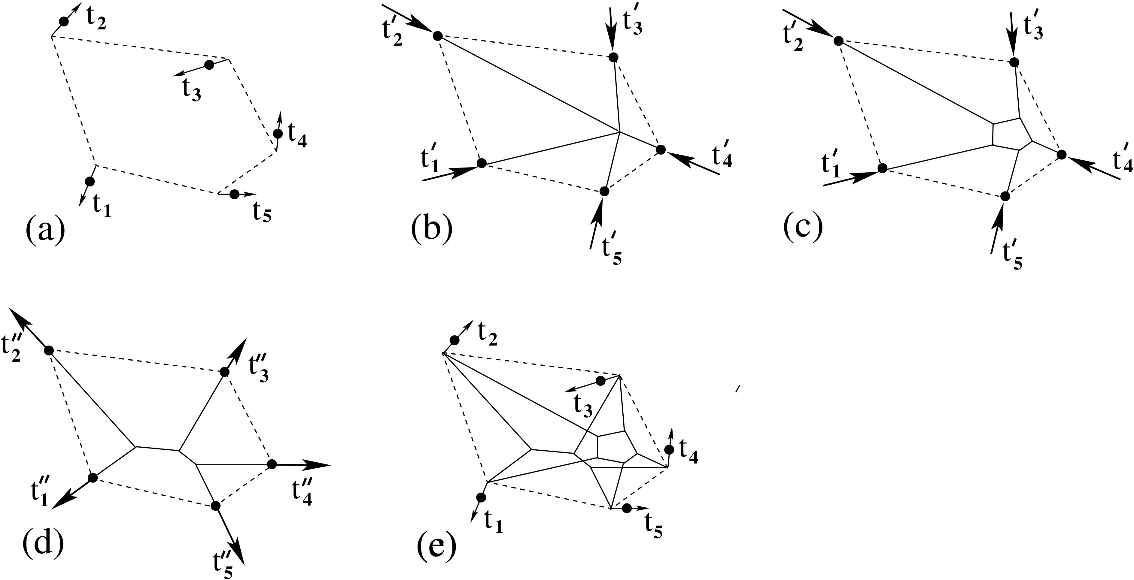 Figure 1
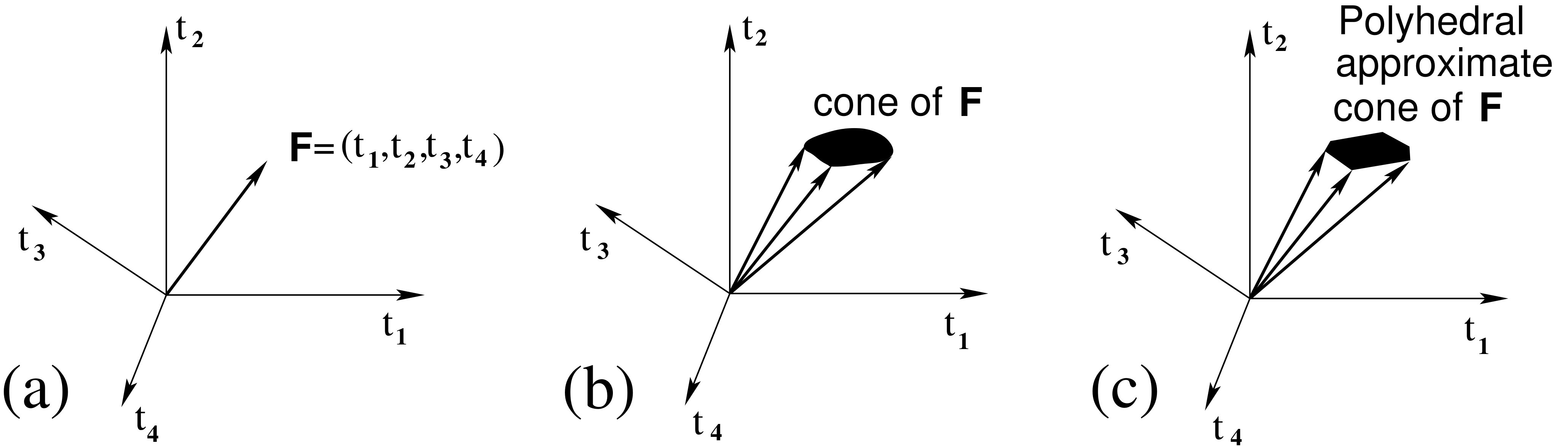 Figure 2
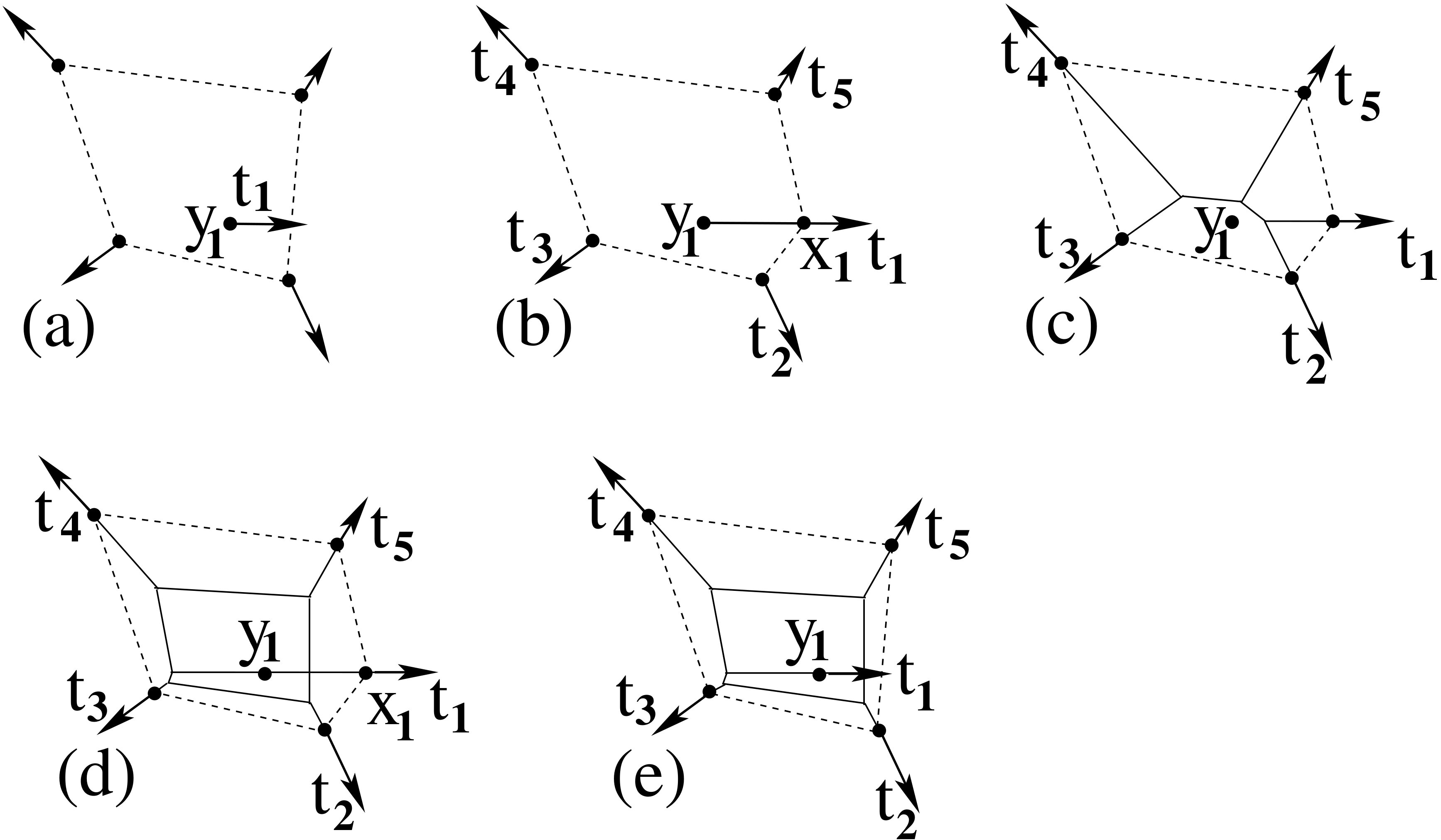 Figure 3
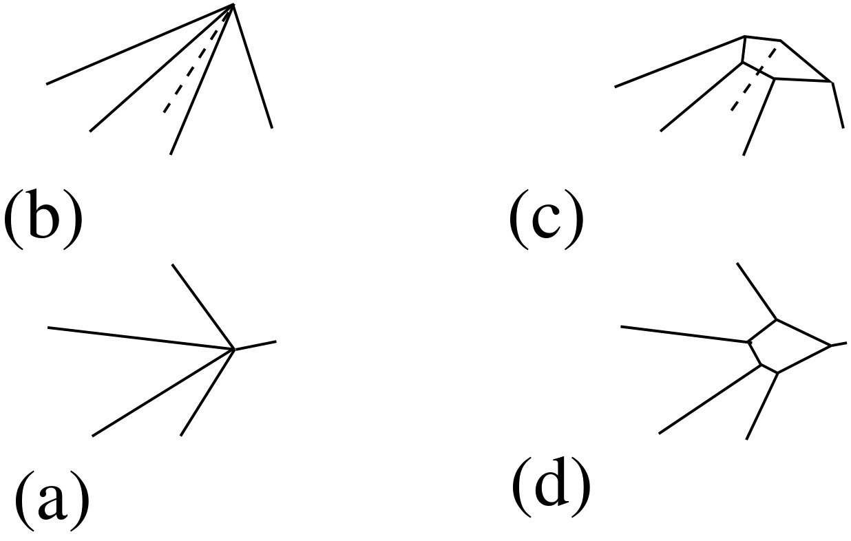 Figure 4
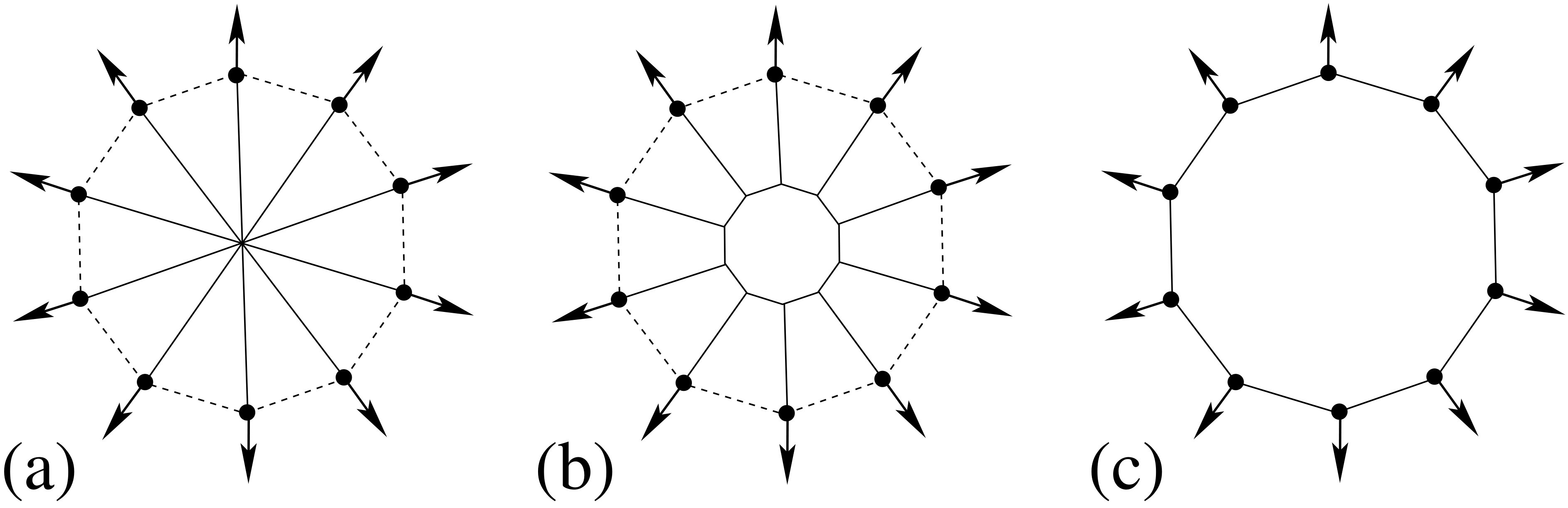 Figure 5
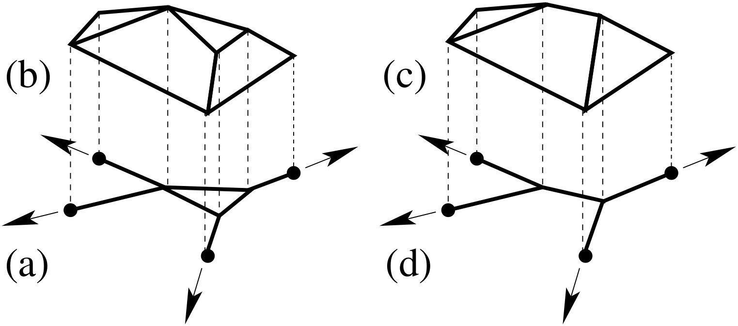 Figure 6
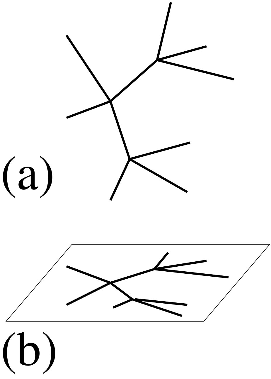 Figure 7
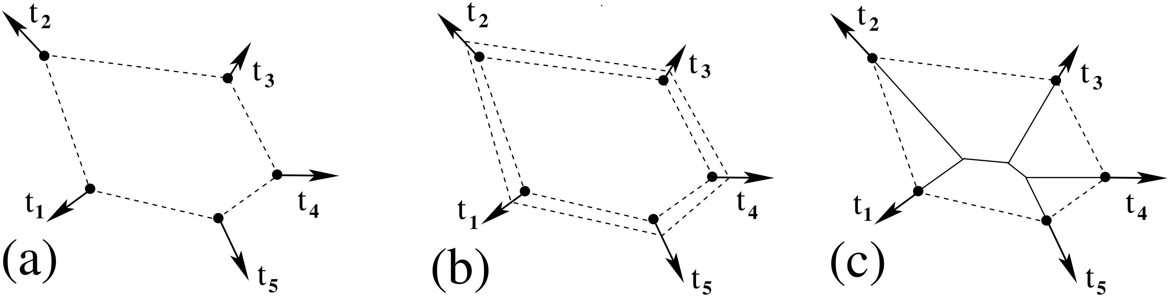 Figure 8
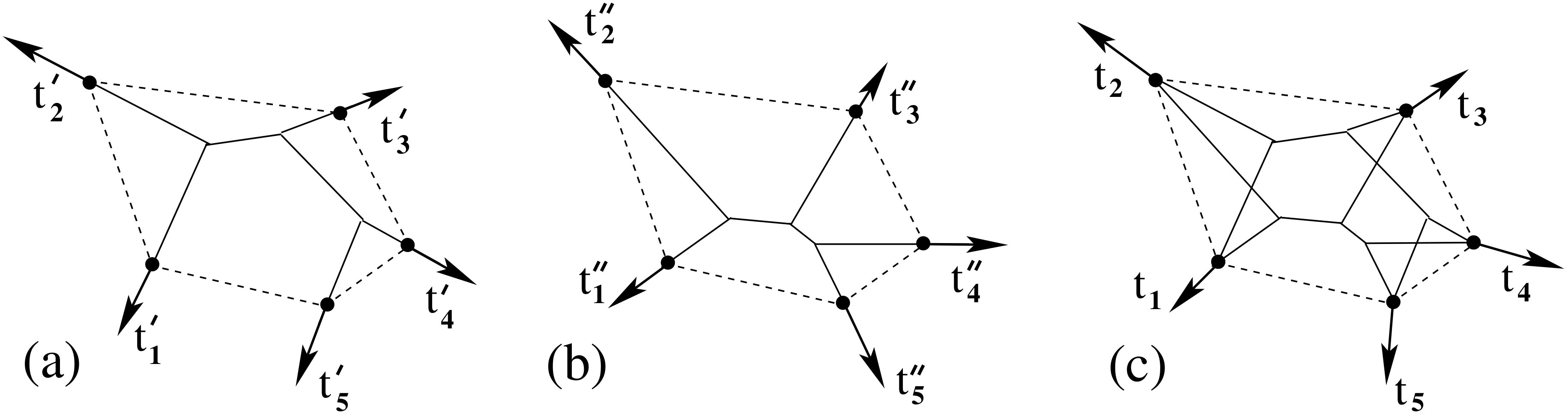 Figure 9
Peer Reviews
No public reviews on file for this paper yet. If you reviewed it on a platform where reviews are public (OpenReview, ICLR, NeurIPS, ICML), you can paste yours below so the community can read it here.
Videos
No videos yet. Explain this paper in a talk, walkthrough, or lecture? Add one.
The set of forces that ideal trusses, or wire webs, under tension can support
Graeme W. Milton
(Department of Mathematics, University of Utah, Salt Lake City, UT 84112, USA
Email: [email protected])
Abstract
The problem of determining those multiplets of forces, or sets of force multiplets, acting at a set of points, such that there exists a truss structure, or wire web, that can support these force multiplets with all the elements of the truss or wire web being under tension, is considered. The two-dimensional problem where the points are at the vertices of a convex polygon is essentially solved: each multiplet of forces must be such that the net anticlockwise torque around any vertex of the forces summed over any number of consecutive points clockwise past the vertex must be non-negative; and one can find a truss structure that supports under tension, and only supports, those force multiplets in a convex polyhedron of force multiplets that is generated by a finite number of force multiplets each satisfying the torque condition. Progress is also made on the problem where only a subset of the points are at the vertices of a convex polygon, and the other points are inside. In particular, in the case where only one point is inside, an explicit procedure is described for constructing a suitable truss, if one exists. An alternative recipe to that provided by Guevara-Vasquez, Milton, and Onofrei [8], based on earlier work of Camar Eddine and Seppecher [2], is given for constructing a truss structure, with elements under either compression or tension, that supports an arbitrary collection of balanced forces at the vertices of a convex polygon. Finally some constraints are given on the forces that a three-dimension truss, or wire web, under tension must satisfy.
Keywords: Trusses; Cable Network; Wire Network; Airy Stress Function
1 Introduction
The analysis of truss structures is fundamental to structural engineering, and a good historical account of the subject can be found in the excellent book of Timoshenko [14], and a more detailed mathematical treatment is given, for example, in the paper of Pellegrino and Calladine [12]. If one wants to prevent buckling in truss structures it is obviously beneficial to have all elements under tension. The question is then: given a set of points and forces acting at them, can one find a truss structure that supports these forces such that all the elements of the truss structure are under tension? We will call the forces a force multiplet where it is not necessary to keep track of since by balance of forces
[TABLE]
Additionally, by balance of torques in the two-dimensional case, we have
[TABLE]
where
[TABLE]
is the matrix for a clockwise rotation. If (1.1) and (1.2) both hold we will say that the set of forces is balanced.
We will say the truss structure supports under tension if all the truss members in the truss structure are under tension. For a fixed set of points , we can also consider the grander question of characterizing those sets of force multiplets, such that one can find single truss structure supporting under tension all of them, but none outside .
In the two-dimensional case of planar truss structures, where are at the vertices of a convex polygon, we obtain an essentially complete answer to both questions. We prove in Section 2 the following theorem:
Theorem 1**.**
A set of points at the vertices of a convex polygon, numbered clockwise, can support balanced forces at these vertices, with a truss with all its elements under tension, if and only if for all and ,
[TABLE]
and we have assumed , if necessary by replacing by and identifying where necessary and with and .
The necessary and sufficient condition (1.4) has a physical interpretation: the net anticlockwise torque around the point of the forces summed over any number of consecutive points clockwise past the point is non-negative. Similarly, as also implied by (1.4) the net clockwise torque around the point of the forces summed over any number of consecutive points anticlockwise past the point is non-negative. If (1.4) is satisfied we provide an explicit recipe for constructing a truss structure that supports the forces, with all truss elements being under tension.
Let be the set of all force multiplets satisfying (1.4), where is given by (1.1). This set is a convex cone in the sense that if and are in then for all and . In section 3 we establish the theorem:
Theorem 2**.**
The set of force multiplets supported by a truss structure under tension is necessarily a convex cone. Conversely, given any polyhedral convex cone contained in , generated by linear multiples with non-negative coefficients of a finite number of force multiplets each satisfying (1.4), then we can find a truss structure that supports under tension, and only supports, those force multiplets in .
We also consider, in Section 4, the case where the points do not all lie at the vertices of a convex polygon. A condition like (1.4) still holds, but it does not always guarantee that there exists a truss under tension supporting the forces. The case where all but one of the points lie at the vertices of a convex polygon is explored in depth and in the appendix an explicit procedure for constructing a suitable truss structure, if one exists, is given. The general case, where more than one point lies inside the convex polygon, seems rather knotty and only some suggestions are made in how to construct an appropriate truss structure.
Since the elements are all under tension we can consider the equivalent problem of designing a wire network of inextensible wires that support the desired force multiplet, or set of force multiplets. Also, by changing the sign of the tensions in each truss element, one sees that the same geometry will support with each element being under compression. This too is an important problem as some materials, such as concrete, have much greater strength under compression than under tension.
This work is motivated by an amazing, but not well known, result of Camar Eddine and Seppecher [2] (see their Theorem 5) who proved by induction that, in three-dimensions, truss structures, with members under either tension or compression, can support an arbitrary force multiplet and in fact an arbitrary linear subspace of force multiplets. (The key to the second result, given the first, is that if one takes a basis for and if for each one finds a truss structure that supports and only , then by superimposing these truss structures, with some minor modifications to avoid collisions in the structures, one obtains a final structure that supports any force multiplet , but no multiplet outside .) Their final objective, which they succeeded in doing for three-dimensional linear elasticity (the two-dimensional problem remains open), was to obtain a complete characterization of the set of all possible local and non-local macroscopic responses in elastic composites built from isotropic elastic materials with arbitrarily small elastic moduli and arbitrarily large elastic moduli. This extended the result of Milton and Cherkaev [11] that any positive definite fourth order tensor satisfying the symmetries of elasticity tensors, can in fact be realized as the effective elasticity tensor of a composite of two isotropic materials, one very compliant and the other very stiff.
The result of Camar Eddine and Seppecher was instrumental in the subsequent work of Guevara-Vasquez, Milton, and Onofrei [8] who extended their construction to two-dimensional truss structures (Theorem 2 in [8]), and moreover obtained a complete characterization, within the framework of linear elasticity, of the dynamic response at the terminal nodes of both two and three-dimensional mass-spring networks (Theorem 4 in [8]). In other words, if in a set of independent measurements, indexed by , one specifies time varying displacements at the points , where is the time, one can say precisely what resultant force functions , , (that total in number) it is possible to generate at these points, allowing for an arbitrary number of internal nodes, and an arbitrary mass (possibly zero) at each internal node. In particular, one can select a desired set of resonant frequencies and one can independently choose any desired response (eigenmode) at each resonant frequency subject only to natural thermodynamic considerations. The complete characterization and synthesis of the response of mass-spring networks with Rayleigh damping, where the stiffness matrix, damping matrix and mass matrix are linearly related, was subsequently obtained by Gondolo and Guevara-Vasquez [7].
Here, in Section 5, we provide an alternative procedure to the inductive one given by Guevara-Vasquez, Milton, and Onofrei [8] (based on the three-dimensional construction of Camar Eddine and Seppecher [2]) for constructing a truss structure that supports an arbitrary collection of balanced forces at points at the vertices of a convex polygon. The basic idea is to superimpose two truss structures: one with all its elements under compression, and the other with all its elements under tension, so that the net forces at the points are the desired ones.
In Section 6 we briefly visit the difficult problem of three-dimensional wire webs. Again a condition like (1.4) is shown to hold for every two-dimensional projection of the web, but we make no progress on the problem of actually constructing webs that support a desired set of forces.
We emphasize that the constraints we provide on a force multiplet supported by a web only rely on the fact that the stress has zero divergence and that all elements are under tension. Thus the constraints apply not just to elastic truss structures, but also to structures with a non-linear elastic response, or possibly to structures under creep or under other plastic deformation, assuming inertial effects can be neglected. However, the constructions we produce that support a desired set of force multiplets do not necessarily minimize the elastic compliance energy associated with the truss structure. Thus they do not, for example, necessarily correspond to a spider web that is in elastic equilibrium, as in that scenario the internal nodes of the web can move to minimize the elastic energy. In fact, to obtain the desired constructions, we ignore elastic energy considerations altogether and treat the struts, or wires, as inextensible. It could be the case that this assumption of inextensiblity can be relaxed, and that our constructions, with an appropriate choice of stiffnesses of the struts, can be made elastically stable. However we do not explore this here. If one wants truss structures built from a single material that minimize the total compliance energy then an excellent approach is to use topology optimization methods: see, for example, chapter 4 of Bendsøe and Sigmund [1] and references therein. If one wants structures, such as formed from concrete reinforced with steel, built from two materials where one material is strong under tension while the other is strong under compression, then a hybridized truss-continuum topology optimization may be appropriate [5]. Other important considerations may affect the design too: such as making sure the stress in the wires, or struts, is not enough to cause damage, or making sure there are no adverse resonance effects in the frequency range in which they are likely to be excited. We emphasize, too, that the truss or wire networks we envisage do not necessarily have any inherent structural rigidity: they need to be attached to the points where the forces are applied to give them structural integrity.
2 Forces at the vertices of a convex polygon
Let us consider what set of forces , , each applied at a vertex of a convex polygon, can be supported by a web under tension attached to these points. Here we assume that the vertices are numbered clockwise around the polygon, and we identify and with and . One elementary constraint is rather clear: the vector must point inside the convex polygon, or equivalently
[TABLE]
where given by (1.3) is the matrix for a clockwise rotation. If this condition does not hold there is no way that the web wires attached to , that are necessarily pulling inside the convex hull, can balance the force . It is also clear that this condition is not sufficient, as the position of the point should not matter in the limit in which the force applied there becomes vanishingly small: in that limit the correct condition should imply that is non-negative.
For two-dimensional elasticity it is well known that in the absence of body forces in a simply connected region the stress field \mbox{\boldmath{\sigma}}({\bf x}), having zero divergence, can be represented in terms of the Airy stress function :
[TABLE]
in which is the transpose of . This is just a restatement of the fact that the stress tensor \mbox{\boldmath{\sigma}}({\bf x}) when expressed in terms of the Airy stress function takes the form
[TABLE]
and if we rotate the matrix on the right by we arrive at the double gradient of . Since \mbox{\boldmath{\sigma}}({\bf x}) is positive semidefinite for all we see that is positive semidefinite for all which implies that has non-negative curvature everywhere within the polygon. Thus the Airy stess function is a convex (or concave) function in any simply-connected two-dimensional region under tension (or compression), that may have subregions with zero stress [6]. When \mbox{\boldmath{\sigma}}({\bf x}) is zero in a region, as it is between the wires in web, then which implies the Airy stress function is a linear function of in this region. Thus the Airy stress function associated with a wire web under tension is a convex polygonal surface with discontinuities of slope along the wires in the web, where the magnitude of the slope discontinuity can be connected to the tension in the associated wire [3, 4].
The essential idea behind the following analysis that will prove theorem 1 is shown in Figure 1. Any network under tension that supports forces at the vertices of a convex polygon as for example in (a), will have an associated Airy stress function that is a convex polyhedron as in (b). We can replace this convex polyhedron by a simpler convex polyhedron, as in (c), formed from the tangent planes at the boundary of the polygon. The lines of discontinuity of slope of this simplified Airy stress function then give an equivalent network that supports under tension the same set of forces as the original network.
Given that the web supports, under tension, the forces at the points it will also support the forces at the points , where
[TABLE]
and one extends the web, as shown in Figure 2(b), by attaching short wires of length between and , . The first step is to determine the Airy stress potential in the polygonal ring bounded on one side by the polygon joining the points , and the polygon joining the points . When is sufficiently small there are no wires inside the quadrilateral with vertices , , , and since the stress vanishes there, the Airy stress potential inside that quadrilateral must be a linear function:
[TABLE]
Continuity of the Airy stress potential at the point then implies
[TABLE]
where and denote the cartesian components of . More generally the line of points where , i.e. where
[TABLE]
must be parallel to the force vector , i.e.
[TABLE]
Across this line jumps from
[TABLE]
and this jump
[TABLE]
can be identified with , implying
[TABLE]
which is consistent with (2.8). Since a linear function can be added to without changing the stress field \mbox{\boldmath{\sigma}}({\bf x}) we can assume without loss of generality that
[TABLE]
Then (2.11) can be used to determine the remaining coefficients and :
[TABLE]
while (2.6) can be used to determine the remaining coefficients :
[TABLE]
Of course, since , and can be identified with , , and which by (2.12) are zero we necessarily have
[TABLE]
which are the expected conditions for balance of force and torque in the system. We have now determined the Airy stress function in the polygonal ring.
Since has non-negative curvature everywhere it must necessarily lie below each tangent plane , which provides the necessary constraints that , or equivalently that
[TABLE]
for all and . This, when expressed in terms of the forces , becomes
[TABLE]
where we have assumed , if necessary by replacing by and identifying where necessary and with and . The condition (2.17) physically says that the net anticlockwise torque around the point of the forces summed over any number of consecutive points clockwise past the point is non-negative. The necessity of condition (1.4) (i.e., (2.17)) in Theorem 1 is thus established. Similarly, as also implied by (2.17) and (2.15), the net clockwise torque around the point of the forces summed over any number of consecutive points anticlockwise past the point is non-negative. By taking , or by taking and using (2.15), we obtain
[TABLE]
which is equivalent to the elementary constraint (2.1).
In fact this condition is also sufficient: given a set of balanced forces , with balanced torques, satisfying (2.17) then there is a web which supports these forces. The web is easily constructed, as in Figure 1(c), by taking the envelope of the tangent planes,
[TABLE]
and placing the web wires where there is a discontinuity in slope in this function. Clearly this is a function with non-negative curvature and which has the desired tangent planes. This web generated in this way is an open web with no closed loops, as illustrated in Figure 1(d) and Figure 2(c). This completes the proof of Theorem 1.
The example of Figure 2(c) suggests that, among the possible webs that support the given forces, the one given by (2.19) may be one of the most efficient in the sense of minimizing the total length of all the wire segments. However it is not always the case as can be seen by the example of forces distributed radially outwards, and all with the same magnitude, around the boundary on a regular polygon with sides. For example, in Figure 3(a) we see that for forces at the vertices of a regular decagon, the wire geometry generated by (2.19) is not as efficient as that in Figure 3(b), which in turn is not as efficient as that in Figure 3(c). Other considerations may be important too in determining the best network to support a given set of forces. For example, following Mitchell [10], one might wish to economize the amount of material used while not exceeding some maximum stress threshold. He points out that the Maxwell Lemma implies that this amount of material is independent of the geometry of the truss network provided one chooses the thicknesses of the struts so that the cross-sectional stress is constant and at the maximum stress threshold throughout the network. As this criterion fails to select the geometry of the network it makes sense to look for other selection criteria that penalize networks with a complicated geometry. Minimizing the total length of all the wire segments is one such criteria, another may be minimizing the number of internal nodes, or perhaps a combiniation of these two criteria. Another consideration is that one might want a network that provides the least obstruction (in some sense that needs to be made precise according to the situation) to the movement of surrounding objects: in this respect the network given by (2.19) might be quite good.
3 Force cones
In this section we consider the set of points at the vertices of a convex polygon as being fixed, and we seek to characterize the complete set of possible loadings that can be supported by a web, not just single loadings.
Consider, for example, the network in Figure 2(c). It can support the forces and . Since these sum to zero we can treat as a ground and only keep track of the force quadruplet . Schematically, as illustrated in Figure 4, we can think of as a vector in a 8-dimensional space, since each vector has two components. Due to balance of torques,
[TABLE]
it suffices, in fact, to represent in a 7-dimensional space. Up to multiplication by a positive constant, this is the only force quadruplet that the network can support. The reason for this is easy to see: since each junction inside the web has exactly three wires meeting at it, by balance of forces the tension in one wire uniquely determines the tension in the other two wires that meet it. Applying this to each junction we see that the tensions in the entire network are uniquely determined once we know the tension in one wire element, i.e. the tensions in the entire network, and hence the boundary forces , are uniquely determined up to a positive multiplicative factor.
Of course there are many networks that support more than one loading. An example is that shown in Figure 3(a). We are free to choose any forces , (numbered clockwise) that point radially outwards from the center of the decagon, provided only that , , , , and . This degeneracy is removed in Figure 3(b) and Figure 3(c) as in those configurations each junction inside the web has exactly three wires meeting at it. More generally, as illustrated in Figure 5, if the wire network generated by the function in (2.19), has junctions where more than 3 wires meet, we can modify by cleaving off the associated parts of , resulting in a network where exactly three wires meet at every junction. This ensures that it supports only the desired force multiplet , and positive multiples thereof.
If a network supports two force multiplets and then it will also support any weighted average , where , with the corresponding Airy stress function being a weighted average of the two. Thus the set of possible force multiplets that any given network (with all wires under tension) can support is necessarily a convex cone as sketched in Figure 4(b).
Any force multiplet must necessarily satisfy (2.17), with . Conversely, we may ask the question: Given any convex cone such that any satisfies (2.17), can we design a web that supports all those force multiplets in but none other? We can answer this approximately. Since is convex we can approximate it by a polyhedral cone, as in Figure 4(c), that consists of all linear sums with positive coefficients of a finite set of force multiplets , each satisfying (2.17). Then we construct webs that support each force multiplet , and only that force multiplet and positive multiples thereof. Finally we superimpose all the webs. An example of this superposition in the case is given in Figure 6.
Of course when we superimpose the networks the wires will cross. If we wish to avoid these crossings, and thus remain in a strictly two-dimensional setting, we may simply join the wires at the crossing point. Suppose the crossing point is taken as the origin. Then if the wires intersect points , , , , with not parallel to , balance of forces at the junction requires the tension in the wire between the origin and to be the same as the tension in the wire between the origin and . Similarly, balance of forces requires the tension in the wire between the origin and to be the same as the tension in the wire between the origin and . Thus the response with the wires joined at the origin is exactly the same as if they just crossed and were not joined: the tensions cannot be distributed any other way when only two wires cross at a point.
It may also be occasionally the case that when we superimpose the networks that a segment of one wire in one network lies exactly on top of another segment of wire in another network. To avoid that we can choose slightly different force multiplets that still approximate the desired cone . This can also be done to avoid the case where a junction in one wire network lies exactly on top of the junction in another network– alternatively, to avoid this, one may make an operation like that in Figure 5 to replace a junctions in one network by junctions in other places.
This completes the proof of Theorem 2.
4 Forces at an arbitrary collection of points in the plane
Let us first consider the case where forces , ,…, are applied respectively at points , ,…, that lie on the vertices of a convex polygon, and an additional force is applied at a point at a point in the interior of the polygon. An example is studied in Figure 9. If we do have a web that supports these forces then we can pick a value of the parameter such that
[TABLE]
together with , ,…, lie on the vertices of a convex polygon with sides. We renumber the points, aside from , so that their numbering increases consecutively as one goes clockwise around the boundary of this sided polygon from . We now join and with a wire and replace the force at by the same force at . Then we can apply the same analysis as in the preceding section and we deduce that the condition (2.17) necessarily must still hold. Notice that the and only depend on the forces , while the only depend on the torques and thus are insensitive to the value of . Hence in this condition (2.17) we are free to replace by .
Whether this condition is also sufficient is a bit more delicate. We can of course construct the function given by (2.19) and the associated open web. The first question is then whether the point lies on the web wire of the associated web that directly attaches to the point . If it does then we can just cut the portion of web wire between and and replace the force at by the same force at , and we are finished.
If it does not, then we can still obtain necessary and sufficient conditions analogous to Theorem 1, for determining whether or not a given set of forces can be supported a network having in particular the force at the point . While we currently do not see any easy way to explicitly write down the needed inequalities, we can determine whether a set of forces can be supported by any network and if so we can construct an appropriate network. This can be done by following the numerical algorithm described in the appendix. The necessary and sufficient conditions are that this algorithm yields the desired network.
To get some insight into this algorithm, recall that the essential idea behind Theorem 1, as conveyed in Figure 1, was that the polygonal Airy surface could be replaced by a simpler Airy surface formed by the tangent planes at the boundary of the convex polygon (at the vertices of which the forces are applied). The essential idea is now similar. If we do have a web that supports the desired forces, with a wire going from to then we can replace the associated polygonal Airy surface by a simpler polygonal Airy surface formed by the tangent planes at the boundary of the convex polygon intersected with the tangent planes to the ridgeline associated with the wire going from to . As the tension in the wire is constant the angle between these latter tangent planes is fixed by the tension. Thus the tangent planes to the ridgeline associated with the wire going from to can be viewed as a collection of roofs, with a known discontinuity of slope at each roof ridgeline, where each roof (when extended) lies above the value of the Airy stress function at the vertices ,…, of the convex polygon. A change from one “roof” to another occurs when the wire going from to crosses another wire in the network. A further simplification of the polygonal Airy surface can be made by lowering and if need be rotating each roof (while keeping the discontinuity in slope across the ridgeline fixed and keeping the downwards projection of the ridgeline coincident with the wire from to ) until it touches the values of the original Airy stress function at two of the vertices ,…, of the convex polygon. (The two degrees of freedom associated with lowering and rotating allow us to match the Airy stress function at two vertices). This leads to the algorithm reported in the appendix.
Now consider the more general case in which forces are applied at points that form the vertices of a convex polygon, and forces are applied at an additional points inside the convex polygon. Now for each point inside the convex polygon we choose a constant such that the set of points
[TABLE]
together with the original points form a convex sided polygon. We renumber the points so that they increase consecutively as one goes clockwise around the boundary of this sided polygon. Then the condition (2.17) must again hold, and must still hold if we replace the with for all points inside the original -sided polygon. The easiest case is if the web associated with (2.19) has on the wire that connects with , for all the interior points . Then we just cut each section of wire between and and replace the force at by the same force at . If the easiest case does not apply then some suggestions for how to proceed are made in the appendix. Aside from the easiest case, the situation is quite complex and probably best tackled numerically.
5 Truss structures with elements under compression or tension that can support an arbitrary collection of forces at the boundary of a convex polygon.
Suppose we wish to construct a truss structure that supports forces at points that are the vertices of a convex polygon and which only supports this loading. The only constraint on the forces are that they are balanced and have zero net torque, i.e., that they satisfy (2.15). Explicit routes to constructing such a structure, even for arbitrarily placed points , has been given in three dimensions by Camar Eddine and Seppecher [2], and in two-dimensions by Guevara-Vasquez, Milton, and Onofrei [8]. Their constructions proceed by induction, and are quite complicated. Here, in the two-dimensional case, we show that when the points are the vertices of a convex polygon, the same result can be obtained very easily, by essentially just superimposing two truss networks: one with all its elements under compression and the second with all its elements under tension.
Clearly the construction is possible if for some small value of a positive parameter we can find a truss structure that supports the forces at the points , where is given by (2.4). We take a point which is a weighted average of the points ,
[TABLE]
where the weights are positive and sum to one. Then, as shown in the example of Figure 7(b), we construct a truss structure consisting of trusses connecting the point to the points , . This truss structure clearly supports forces where
[TABLE]
and the trusses will all be under compression if is positive. The weights are required to be chosen so and are not parallel for any . Having obtained this structure we now ensure that it only supports the force multiplet , and positive multiples thereof, by replacing the spoke structure issuing from by a ring structure, as in Figure 7(c).
We then construct, as in Figure 7(d), a web of wires, or a truss structure, that supports and only supports, the forces at the points and is such that all the trusses in this structure (or wires in the web) are under tension. This requires that be chosen sufficiently large that (2.17) holds when the are replaced by the forces :
[TABLE]
or equivalently
[TABLE]
where the quantity on the right is negative when and because the truss structure that supports the forces at the points has all its truss elements under compression, and thus must satisfy the reverse inequality to (2.17) when the are replaced by the forces . The parameter must be chosen so this inequality holds for all and with , i.e.,
[TABLE]
where we have excluded the case in which , since then (5.4) is trivially satisfied since both sides are zero.
Finally, short truss segments are joined from the points to the points , and the force at is replaced by the same force at . The addition of these small truss segments ensures that the structure only supports one loading.
6 Three-dimensional webs
Three-dimensional webs are of course much harder to analyse. Some constraints on the forces a web can support can be obtained by projecting the three-dimensional web onto a two-dimensional space. So, for example, we can consider the two-dimensional web obtained by “photographing” the three-dimensional web from above, as illustrated in Figure 8. If the web is such that it supports forces
[TABLE]
then the projected two-dimensional web will support forces
[TABLE]
Thus, for example, at a junction of -wires in the three-dimensional web, if we have balance of the forces that each wire exerts on the junction,
[TABLE]
then we will have balance of the forces that each projected wire exerts on the junction of the projected two-dimensional web:
[TABLE]
Thus the three-dimensional forces must be such that the condition (2.17) holds, once we have appropriately renumbered the points, and the corresponding forces. Recall that to do this renumbering we need to take the convex hull of the points and for points in the interior replace them by points , where , that are just outside the original convex hull. Then one numbers the points going clockwise around the boundary of the new convex hull.
This renumbering makes the explicit constraint on the not so easy to write down. A simpler, but perhaps weaker, condition can be obtained by attaching wires to all points where we apply forces that go infinity in the direction of . Then it is the values of going clockwise around the unit circle that determine the ordering. Of course this ordering will depend on which projection we choose to take.
There are other, possibly additional, constraints on three-dimensional web. For example, suppose there is a strain field
[TABLE]
such that \mbox{\boldmath{\epsilon}}_{0}({\bf x}) is defined and positive semidefinite, say within the convex hull of the points . For example one could take and require that has positive semidefinite curvature \nabla\nabla\psi({\bf x})=\mbox{\boldmath{\epsilon}}_{0}({\bf x}). Then we have the inequality
[TABLE]
Of course there are similar inequalities in the two-dimensional case, but when the points are at the vertices of a convex polygon the analysis in Section 2, shows that they do not provide any restrictions that are additional to the constraints (2.17) as these are in fact necessary and sufficient. Thus, in the three-dimensional case, it is unclear whether (6.6) provides additional restrictions or not.
We observe that a three-dimensional web geometry such as that in Figure 8(a) has an important feature. Each junction inside the web has exactly four wires meeting at it, and so by balance of forces the tension in one wire uniquely determines the tension in the other three wires that meet it. Applying this to each junction we see that the tensions in the entire network are uniquely determined once we know the tension in one wire element, i.e. the tensions in the entire network, and hence the boundary forces , are uniquely determined up to a positive multiplicative factor. Thus this web can only support one force multiplet, up to a positive multiplicative factor. This same feature accounts for why pentamode materials, introduced in [11, 13] and experimentally realized in [9] essentially support only one stress field.
Acknowledgements
G.W. Milton thanks the National Science Foundation for support through grant DMS-1211359. Lorenzo Bardella and Ole Sigmund are thanked for providing some useful references, Ornella Mattei is thanked for spotting some corrections that needed to be made, and Pierre Seppecher is thanked for stimulating discussions. The two anomomous referees are thanked for their helpful comments.
7 Appendix: Constructing suitable web networks when the forces are applied at points which are not the vertices of a convex polygon
Let us first consider the case where forces , ,…, are applied respectively at points , ,…, that lie on the vertices of a convex polygon, and an additional force is applied at a point at a point in the interior of the polygon. The point given by (4.1) is such that all points , ,…, are the vertices (renumbered clockwise) of a new convex polygon. We now provide an algorithm for constructing a desired web supporting the force at and the forces , ,…, at the points , ,…, , if such a web exists. The first step is to check if the web associated with given by (2.19) has on the wire that connects with . If it does, then we are finished as we can just cut the portion of web wire between and and replace the force at by the same force at . If it does not, as in the example of Figure 9(c), then we have to move on to the next step.
The next step is to extend the ridgeline of the function going from the point . We want the ridgeline to remain vertically below the linear extension of the ridgeline that goes from , and we want the jump in across the ridgeline to remain the same, as it corresponds to the stress in the wire. Accordingly let us define the roof function
[TABLE]
By appropriately adjusting , , and there are three operations we can do on the roof:
Raising or lowering the roof by increasing or decreasing ; 2. 2.
Swaying the roof by keeping the ridgetop line fixed and rotating the roof about this line (but not allowing either roof faces to move beyond a vertical orientation); 3. 3.
Tilting the roof by increasing the angle between the rooftop ridgeline and the rooftop ridgeline of
For a given tilt we can lower the roof and sway it until it just touches at least two of the base points , but remains above the other base points, and cannot be lowered further or swayed. This then defines the roof function . Now we consider
[TABLE]
where is defined by (2.19). We increase the tilt until the projection of the ridgeline down on the -plane passes through the desired point . If this is impossible, then there is no web that supports the forces. If it is possible, and no breaks have occurred in the ridgeline, then in the associated web we cut the portion of web wire between and and replace the force at by the same force at , and we are finished. Then the web has one closed loop, as in the example of Figure 9(c), and the force acting at is attached by wire to one of the vertices of this closed loop. It is conceivable that a break has occurred in the ridge line, and in that case to close the break we may need to take
[TABLE]
with appropriate values of , that are clearly non-unique, and chosen to close the break, or breaks, in the ridgeline. If this is impossible, then there is no web that supports the forces.
Now let us briefly shed some light (but not completely solve) the difficult case when forces are applied at points that form the vertices of a convex polygon, and forces are applied at an additional points inside the convex polygon. From the points we construct associated points given by (4.2), that are chosen so that they, together with the original points , are the vertices of a new convex polygon, and renumbered so the numbering goes clockwise around the new convex polygon. We assume that the easiest case, where the web associated with given by (2.19) has on the wire that connects with , for all the interior points , does not hold. Then it makes sense to introduce the roof functions,
[TABLE]
A suitable web, if it exists, should be obtained by taking a minimum over a set of functions consisting of and an appropriate choice of roof functions . It is no longer that case that one should lower the roof functions as much as possible, as such a lowering could significantly shorten some other ridgelines. It seems likely that there could be competition between lengthening one ridge line, and lengthening another ridge line. It may happen for some and , with that the wire between and crosses the wire between and at some point . In that case one should introduce the pyramid roof functions
[TABLE]
where the three parameters , , and are chosen so the line of discontinuity in slope of that meets the ridgeline of and the ridgeline of at the top of the pyramid corresponds to the wire between and , and the jump in slope across this line corresponds to the tension in that wire. Then one should take to be the minimum of , and possibly other appropriate roof functions, where , , and need to be suitably chosen. In this scenario one may not need to explicitly use the roof functions . In the event that lies on the ridgeline of that reaches it may suffice to take .
The reference list from the paper itself. Each links out to its DOI / PubMed record.
- 1[1] M. P. Bendsøe and O. Sigmund , Topology Optimization: Theory, Methods, and Applications , Springer-Verlag, Berlin, Germany / Heidelberg, Germany / London, UK / etc., second ed., 2004, doi:http://dx.doi.org/10.1007/978-3-662-05086-6 , http://www.loc.gov/catdir/enhancements/fy 0815/2002030512-d.html;http://www.loc.gov/catdir/enhancements/fy 0815/2002030512-t.html . · doi ↗
- 2[2] M. Camar-Eddine and P. Seppecher , Determination of the closure of the set of elasticity functionals , Archive for Rational Mechanics and Analysis, 170 (2003), pp. 211–245, doi:http://dx.doi.org/10.1007/s 00205-003-0272-7 , http://link.springer.com/article/10.1007/s 00205-003-0272-7 . · doi ↗
- 3[3] F. Fraternali, M. Angelillo, and A. Fortunato , A lumped stress method for plane elastic problems and the discrete–continuum approximation , International Journal of Solids and Structures, 39 (2002), pp. 6211–6240, doi:https://doi.org/10.1016/S 0020-7683(02)00472-9 , http://www.sciencedirect.com/science/article/pii/S 0020768302004729?via%3Dihub . · doi ↗
- 4[4] F. Fraternali and G. Carpentieri , On the correspondence between 2D force networks and polyhedral stress functions , International Journal of Space Structures, 29 (2014), pp. 145–159, doi:https://doi.org/10.1260/0266-3511.29.3.145 , http://journals.sagepub.com/doi/10.1260/0266-3511.29.3.145 . · doi ↗
- 5[5] A. T. Gaynor, J. K. Guest, and C. D. Moen , Reinforced concrete force visualization and design using bilinear truss-continuum topology optimization , Journal of Structural Engineering, 139 (2013), pp. 607–618, doi:http://dx.doi.org/10.1061/(ASCE)ST.1943-541X.0000692 . · doi ↗
- 6[6] M. Giaquinta and E. Giusti , Researches on the equilibrium of masonry structures , Archive for Rational Mechanics and Analysis, 88 (1985), pp. 359–392, doi:http://dx.doi.org/10.1007/BF 00250872 . · doi ↗
- 7[7] A. Gondolo and F. Guevara Vasquez , Characterization and synthesis of Rayleigh damped elastodynamic networks , Networks and Heterogeneous Media (NHM), 9 (2014), pp. 299–314, doi:http://dx.doi.org/10.3934/nhm.2014.9.299 , https://www.aimsciences.org/journals/display Articlesnew.jsp?paper ID=10083 . · doi ↗
- 8[8] F. Guevara Vasquez, G. W. Milton, and D. Onofrei , Complete characterization and synthesis of the response function of elastodynamic networks , Journal of Elasticity, 102 (2011), pp. 31–54, doi:http://dx.doi.org/10.1007/s 10659-010-9260-y , http://link.springer.com/article/10.1007/s 10659-010-9260-y . · doi ↗