Chirality-mediated bistability and strong frequency downshifting of the gyrotropic resonance of a dynamically de-stiffened magnetic vortex
Manu Sushruth, Jasper Fried, Abdelmadjid Anane, Stephane Xavier,, Cyrile Deranlot, Vincent Cros, Peter Metaxas

TL;DR
This paper shows how introducing a flat edge in a magnetic vortex disk enables enhanced, bidirectional tuning of gyrotropic resonance frequencies, revealing chirality-dependent bistability and significant frequency downshifting.
Contribution
It introduces a flat edge to control and enhance the gyrotropic resonance tuning and reveals chirality-mediated bistability in magnetic vortices.
Findings
Range of gyrotropic frequencies more than doubled
Chirality-dependent bistability observed
Significant frequency downshifting achieved
Abstract
We demonstrate an enhanced, bidirectional, in-plane magnetic field tuning of the gyrotropic resonance frequency of a magnetic vortex within a disk by introducing a flat edge. When the core is in its vicinity, the flat edge locally reduces the core's directional dynamic stiffness for movement parallel to the edge. This strongly reduces the net dynamic core stiffness, leading to the gyrotropic frequency being significantly less than when the core is centered (or located near the round edge). This leads to the measurable range of gyrotropic frequencies being more than doubled and also results in a clear chirality-mediated bistability of the gyrotropic resonance frequency due to what is effectively a chirality-dependence of the core's confining potential.
Click any figure to enlarge with its caption.
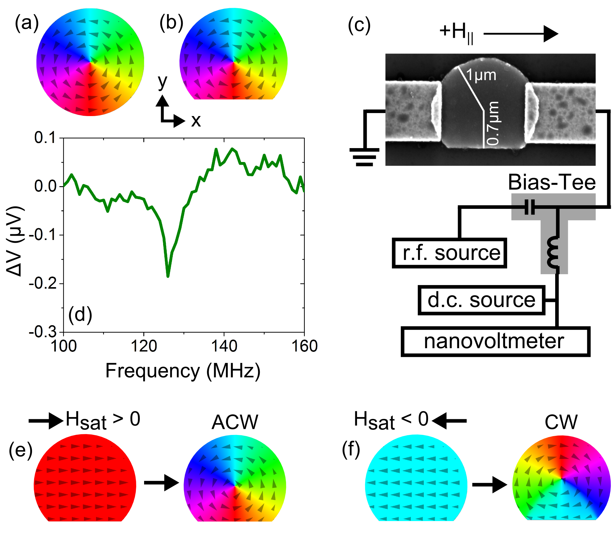 Figure 1
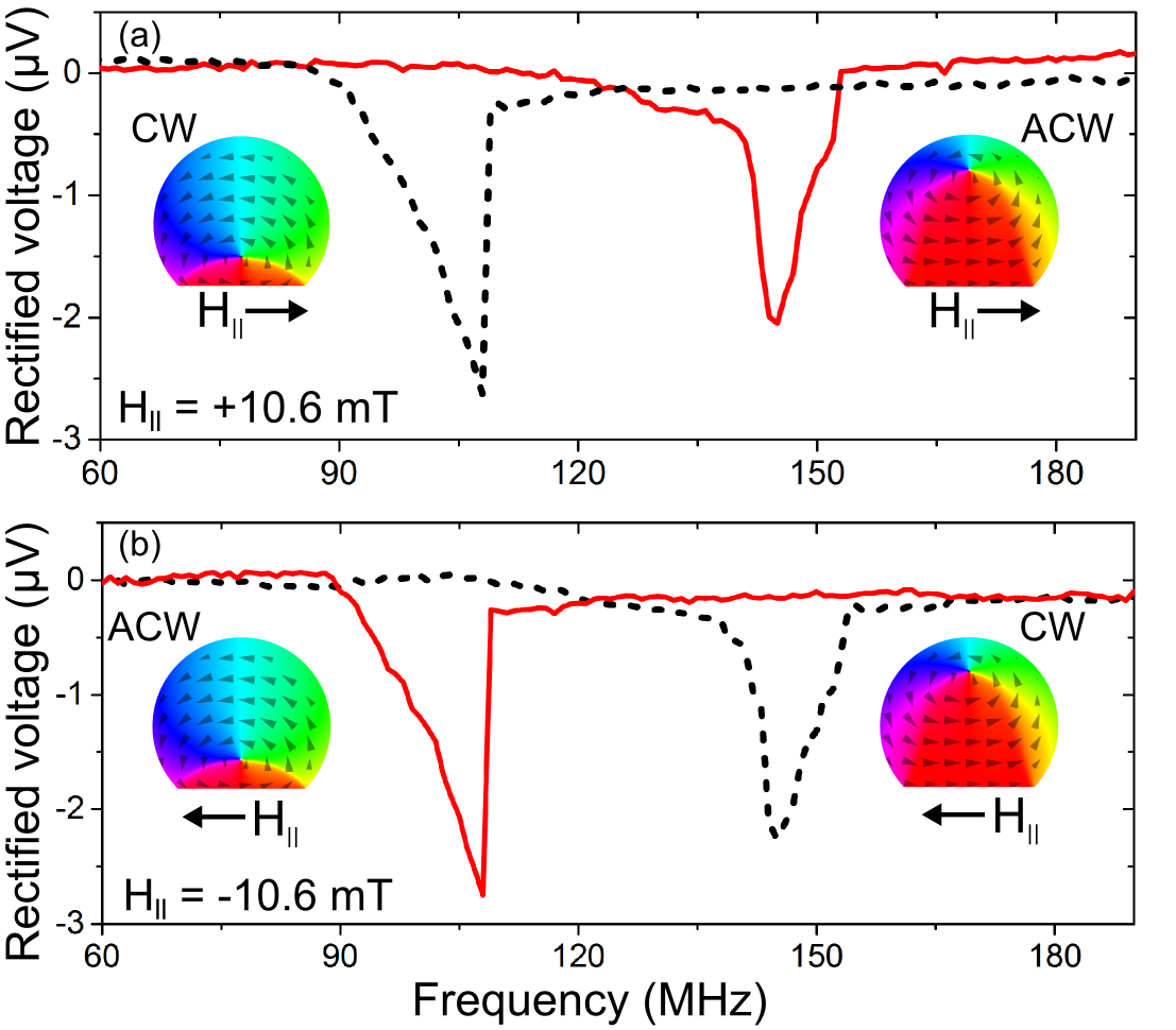 Figure 2
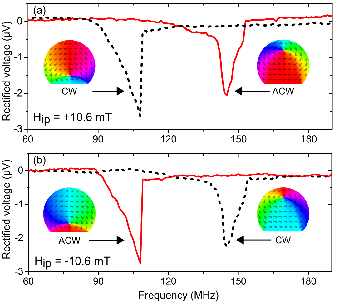 Figure 3
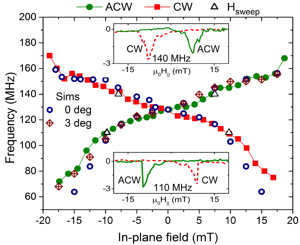 Figure 4
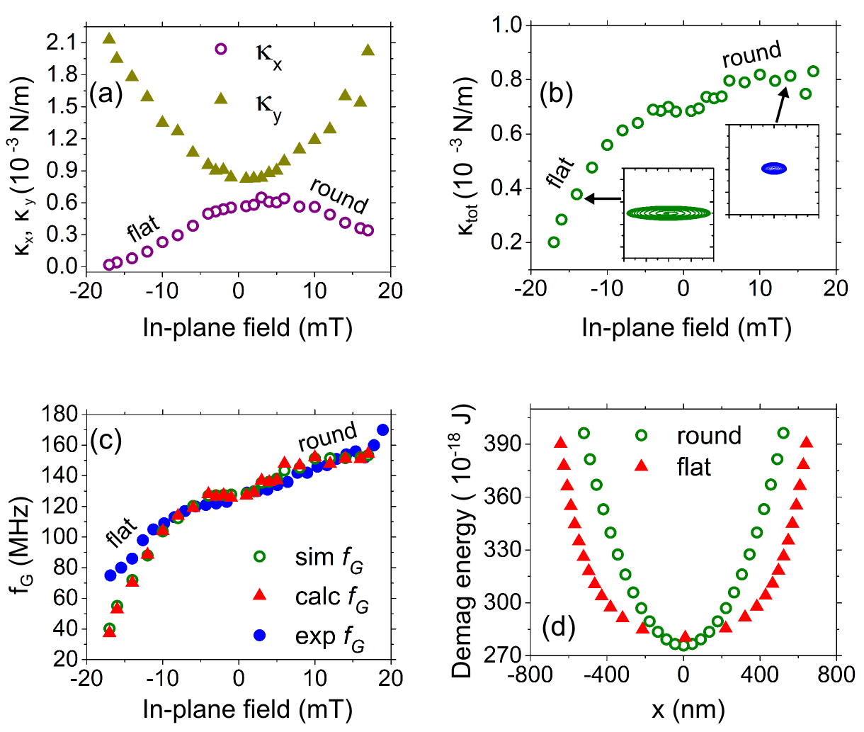 Figure 5
Peer Reviews
No public reviews on file for this paper yet. If you reviewed it on a platform where reviews are public (OpenReview, ICLR, NeurIPS, ICML), you can paste yours below so the community can read it here.
Videos
No videos yet. Explain this paper in a talk, walkthrough, or lecture? Add one.
Chirality-mediated bistability and strong frequency downshifting of the gyrotropic resonance of a dynamically de-stiffened magnetic vortex
Manu Sushruth
School of Physics and Astrophysics, M013, University of Western Australia, 35 Stirling Hwy, Crawley WA 6009, Australia.
Jasper P. Fried
School of Physics and Astrophysics, M013, University of Western Australia, 35 Stirling Hwy, Crawley WA 6009, Australia.
Abdelmadjid Anane
Unité Mixte de Physique, CNRS, Thales, Univ. Paris-Sud, Université Paris-Saclay, 91767 Palaiseau, France.
Stephane Xavier
Thales Research and Technology, 1 Avenue A. Fresnel, 91767 Palaiseau, France
Cyrile Deranlot
Unité Mixte de Physique, CNRS, Thales, Univ. Paris-Sud, Université Paris-Saclay, 91767 Palaiseau, France.
Vincent Cros
Unité Mixte de Physique, CNRS, Thales, Univ. Paris-Sud, Université Paris-Saclay, 91767 Palaiseau, France.
Peter J. Metaxas
School of Physics and Astrophysics, M013, University of Western Australia, 35 Stirling Hwy, Crawley WA 6009, Australia.
School of Mechanical and Chemical Engineering, M050, University of Western Australia, 35 Stirling Hwy, Crawley WA 6009, Australia.
Abstract
We demonstrate an enhanced, bidirectional, in-plane magnetic field tuning of the gyrotropic resonance frequency of a magnetic vortex within a disk by introducing a flat edge. When the core is in its vicinity, the flat edge locally reduces the core’s directional dynamic stiffness for movement parallel to the edge. This strongly reduces the net dynamic core stiffness, leading to the gyrotropic frequency being significantly less than when the core is centered (or located near the round edge). This leads to the measurable range of gyrotropic frequencies being more than doubled and also results in a clear chirality-mediated bistability of the gyrotropic resonance frequency due to what is effectively a chirality-dependence of the core’s confining potential.
Magnetic vortices are curled magnetization configurations that arise naturally in thin magnetic elements with lateral dimensions from m to a few m Cowburn et al. (1999); Shinjo et al. (2000); Wachowiak et al. (2002); Guslienko (2008). They are characterized by an in-plane, curling magnetization which surrounds an out-of-plane magnetized nano-scale region known as the vortex core [Fig. 1(a)]. Magnetic vortices are examples of topological solitons or defects and can display dynamic behavior which is intrinsically nonlinear Buchanan et al. (2007); Guslienko et al. (2010); Drews et al. (2012); Guslienko et al. (2008); Lee et al. (2008), a characteristic which has generated significant theoretical interest.
The potential for device applications Pigeau et al. (2010); Jung et al. (2011); Huber and Grundler (2011), which include tuneable radiofrequency signal generators/detectors Pribiag et al. (2007); Dussaux et al. (2010); Jenkins et al. (2016) and data storage devices Pigeau et al. (2010), has strongly motivated studies in tuning the frequency of the gyrotropic resonance of magnetic vortices, . This resonance involves the vortex core following an orbit-like path around its equilibrium position Argyle et al. (1984); Guslienko et al. (2002); Park et al. (2003); Choe et al. (2004); Novosad et al. (2005). The gyrotropic resonance frequency is proportional to the vortex stiffness Guslienko et al. (2002), , which is typically determined by a geometrically induced, primarily magnetostaticGuslienko et al. (2002, 2006), core confining potential (there can also be non-negligible contributions from exchange interactionsFried and Metaxas (2016) or current-generated Oersted fieldsDussaux et al. (2012)). Although the confining potential can be treated as harmonic for small radial core displacements ( where is the system energy and the radial core displacement), it is typically anharmonicSukhostavets et al. (2013), meaning that , and thus , are both dependent on the position of the vortex core. For example, in circularSukhostavets et al. (2013); Gangwar et al. (2015); Sushruth et al. (2016) disks (as well as in elliptical disks, although the behavior there is slightly more complexBuchanan et al. (2006)), the gyrotropic frequency becomes higher as the core is displaced from the disk’s center due to a core stiffening.
In this letter we present results on vortex core dynamics in a ferromagnetic disk that has one side which has been made flat (‘chopped’) [Fig. 1(b)]. The flat edge enables control over the vortex chirality Schneider et al. (2001); Huang et al. (2013); Nakatani et al. (2005); Kimura et al. (2007); Dumas et al. (2011); Huang et al. (2010); Wu et al. (2008) which describes the direction of the (clockwise or anti-clockwise) curling magnetization. The chirality is critical in this study as it determines the lateral direction that a core will be displaced under the action of a given static in-plane magnetic field Schneider et al. (2001). Chirality control thus enables core displacement control. Despite both the flat and round edges being repulsive to the core under static displacements towards the edge, we show that a core undergoing gyrotropic motion near the flat edge exhibits a strongly reduced dynamic stiffness when moving along the flat edge (i.e. perpendicular to the direction of the static displacement). As a result, the net dynamic core stiffness Buchanan et al. (2006) is also reduced, leading to at the flat edge being lower than for the disk-centered core. can thus either be strongly increased (by shifting the core towards the disk’s round edge) or decreased (by moving the core towards the flat edge). This leads to the range of accessible -values being approximately doubled (i.e. we can both significantly increase and decrease relative to its value for a non-displaced vortex in zero field). We note that frequency downshifting has also been observed in square ferromagnetic elementsLangner et al. (2013); Cui et al. (2016) and, to a lesser degree, in triangular elements Yakata et al. (2013) when moving the core towards a flat edge within the element.
A final consequence of the geometrical asymmetry in our system is that the vortex is characterized by a clear chirality-induced, dynamic bistability. Indeed, for a given, finite, static in-plane magnetic field (applied such that it acts to displace the core perpendicular to the disk’s flat edge), two values of can be observed depending on the vortex chirality. This is reminiscent of the polarity-induced bistability studied by de Loubens et al de Loubens et al. (2009). Here however, it is chirality-mediated and arises because, for a given in-plane field polarity, the chirality determines which part of the asymmetric confining potential the gyrating core is subject to.
A scanning electron microscope image of a chopped disk is shown in Fig. 1(c). The distance from the disk’s center to the round edge is 1 m (radius of the circular part of the disk) while the shortest distance from the disk’s center to the flat edge is 0.7 m. Disks were fabricated from a continuous sputtered //NiFe(30 nm)/Au(8 nm) layer via Argon ion milling using a hard Ti mask defined by electron beam lithography (NanoBeam Limited). Evaporated lateral contacts were defined using electron beam lithography and liftoff. Auger spectroscopy suggests that approximately 30 nm of Ti remains on the top of the NiFe/Au chopped disk Sushruth et al. (2016). The measured device was wire bonded to a sample mount which was placed between the poles of an electromagnet in such a way that a static, in-plane magnetic field, , could be applied along the flat edge of the disk (note that simulations detailed below will suggest the presence of a small misalignment of between the field and the disk’s flat edge). A nanovoltmeter (200 ms integration time) was used to measure the voltage across the device in the presence of injected dc or rf currents [Fig. 1(c)]. The rf source output power was -14 dBm.
An rf current injected across the device generates a transverse, rf Oersted field in the lower NiFe layer which can drive gyrotropic core motionSushruth et al. (2016). On resonance, this generates an oscillation in the sample’s resistance (via anisotropic magnetoresistance, AMR) which can mix with the input rf current to generate a measurable rectified voltage and enable the electrical identification of Kasai et al. (2006); Kim et al. (2010); Goto et al. (2011a, b); Gangwar et al. (2015); Sushruth et al. (2016). In Fig. 1(d) we show the rectification peak obtained in the chopped disk at zero applied field from which we can extract MHz. This value matches closely with the simulated MHz at (see below). Note that in circular disks, a rectification peak is not generated for due to the symmetry of the core trajectory around the center of the disk which results in the generated voltage time-averaging to zeroSugimoto et al. (2014); Sushruth et al. (2016). In contrast, the chopped disk geometry leads to the core’s equilibrium position being shifted away from the circular center of the element even for [Fig. 1(b)] which enables the generation of a finite amplitude peak. This result is discussed further in Supplementary Figure 1111. Supplementary information to be provided at a later date..
The vortex chirality defines the direction of the core shift for a given Schneider et al. (2001). For example, a positive shifts the core to the round edge for an ACW vortex but shifts it to the flat edge for a CW vortex [insets of Fig. 2]. Micromagnetic simulations performed using the MuMax3 micromagnetic codeVansteenkiste et al. (2014) demonstrate the ability to choose the vortex chirality in the chopped disk by starting from an in-plane saturated state and then returning the field to zero [Figs. 1(e,f)]. In the simulations, we used 30 nm thick cells with lateral dimensions of nm2 ( cells for the m2 simulation region)222Frequencies obtained using a full z-discretization (8 cells) were within 1.6 MHz of those obtained with a single z-discretization.. We then initialized the system with a uniform magnetization parallel to the flat edge and let the magnetization evolve towards a final, converged state in zero magnetic field with damping parameter (saturation magnetization = 800 kA/m; exchange stiffness = 13 pJ/m; nil anisotropy; rad(T.s)-1 which is within % of the experimentally determined value Shaw et al. (2013)). We find that the initial direction of the magnetization along the flat edge remains fixed upon the return to zero field and thus defines the chirality of the relaxed, curled vortex state [Figs. 1(e,f)]. Note that the simulated transition to the single vortex state proceeds via a non-trivial intermediate state analogous to that seen in Co disks with widths nmDumas et al. (2011). Experimentally, the left and right saturated magnetic states are approximated by applying an in-plane saturating field, T, along the flat edge of the disk [Figs. 1(e,f)]. In Supplementary Figure 2. Note (1) we confirm our ability to choose the core chirality by exploiting differences in the vortex annihilation fields at the flat and round edgesHuang et al. (2013) (as well as general differences in the quasi-static magnetization reversal process). Dynamic results presented below will also confirm our ability to set the chirality and controllably displace the core towards the flat or round edge of the disk.
We now use the on-resonance rectification to experimentally measure the influence of the core’s equilibrium position on . We first set a CW vortex chirality, return to zero field and then apply mT. This shifts the core towards the disk’s flat edge [Fig. 2(a), left]. An rf signal is then injected across the disk, sweeping from low frequency to high frequency, enabling us to determine MHz (black dashed lines in Fig. 2(a)). Note that the measured frequency is significantly lower than the value found at in Fig. 1(d) ( MHz). Repeating the measurement for an ACW chirality at the same field allows us to probe core dynamics at the round edge of the disk [Fig. 2(a), right] for which we find MHz [solid red line in Fig. 2(a)]. This confirms the chiral bistability in that we can observe two different values of for a fixed , depending on the vortex chirality. Changing the polarity of changes the direction of the core displacement for a given chirality. As such, for mT [Fig. 2(b)], it is now the CW vortex core which moves to the round edge of the disk, resulting in it having the higher .
The results of experiments carried out for both chiralities are given in Fig. 3, showing the full evolution of with . An example of peaks obtained by carrying out field sweeps at fixed frequency (field-resolved measurements) are also shown as insets in Fig. 3 and show good agreement with the frequency-resolved data. Note that there are two data sets in Fig. 3 corresponding to CW (filled squares) and ACW (filled circles) vortices. Here, it is again clear that for a given finite in-plane field, can be either above or below the zero field value of depending on the vortex chirality with low frequencies obtained when the core is shifted towards the flat edge ( for an ACW vortex and for a CW vortex). Also note that the difference between values for the two chiralities increases with as the core is pushed further away from the disk’s center. Simulated gyrotropic frequencies (open circles) for different chiralities and values are also shown in Fig. 3 with good agreement between the simulation and experimental results. Note however that the best agreement is obtained by including a misalignment of between and the flat edge (this causes the core to be slightly displaced towards the point where the flat edge meets the disk’s round edge, slightly increasing the stiffness and thus ; see Supplementary Figure 3). To obtain simulated values, we performed field-pulse-driven ‘ringdown’ simulations333After relaxing the system at the given value [applied along the -axis as per Fig. 1(a)], we apply an in-plane sinc field pulse along the -axis [as per Fig. 1(a)] with an amplitude of 2 mT, a 300 ps time offset and a cut-off frequency of 30 GHz. This induces damped gyrotropic core dynamics around the core’s -dependent, equilibrium location. The resulting time trace of the component of the system’s spatially averaged magnetization is then Fourier analyzed to extract . (e.g.McMichael and Stiles (2005); Fried et al. (2016)) for a number of values.
To understand the observed drop-off in for cores at the flat edge of the disk, we look at the relationship between and the core stiffness which depends not only on the location of the core but the direction of core movementBuchanan et al. (2006):
[TABLE]
Above, and correspond to the local core stiffness in the and directions [defined in Fig. 1(a,b)] and is the gyroconstant Thiele (1973); Huber (1982); Guslienko et al. (2002) (considered field-independent here). Note that in a circularly symmetric systemGuslienko et al. (2006, 2002), is simply given by with here replacing the otherwise direction-independent “”. The stiffness coefficient along an axis is defined via (valid for smallSukhostavets et al. (2013) ) where is the energy of the system. An accurate description of dynamics must however take into account the energy of the moving core rather than static displacementsBuchanan et al. (2006); Fried and Metaxas (2016). To extract the dynamic from micromagnetic simulations, core dynamics were driven using an in-plane sinusoidal field with an amplitude of 5 T and frequency equal to as obtained from the ringdown simulationsFried et al. (2016). and were then extracted from parabolic fits to the total system energy as a function of core displacement along the and directions respectively.
Fig. 4(a) shows the extracted and values versus in-plane field for an ACW vortex for which a negative will displace the core toward the disk’s flat edge. Although is relatively symmetric about mT, , related to displacements along the flat edge of the disk, is clearly asymmetric and lowest when the core is located near the flat edge (). This is despite that edge of the disk being repulsive in terms of static displacements of the core towards it [i.e. the equilibrium position of the static core at remains relatively close to the disk’s center; Fig. 1(b)]. The asymmetry in is critical to understand the drop-off in as it leads to a strong local reduction in the term [Fig. 4(b)] which in turn leads to a strong reduction in as per Eq. (1). Indeed the predicted from the extracted and values using Eq. (1) can be used to accurately reproduce the simulated frequencies which in turn approximate the measured frequencies well [Fig. 4(c)].
The reduced value of at the disk’s flat edge is primarily due to a weaker dependence of the demagnetizing-energy on the -position of the core at that side of the element (contributions from demagnetizing, exchange and Zeeman energies are compared in Supplementary Figure 4. Note (1) for the chopped and unchopped disk). This weaker dependence can be directly visualized in Fig. 4(d) where we show the change in the system’s demagnetizing energy for a core that is quasi-statically shifted approximately laterally along the flat and round edges via a -oriented magnetic field. One sees that small lateral displacements near the curved edge lead to larger changes in the demagnetizing energy (per unit displacement) than do lateral displacements along the flat edge. At least for static magnetization configurations with laterally shifted cores, the demagnetizing energy (as well as the displacement-induced change in the demagnetizing energy) is concentrated within lines that join the core to positions which are close to the meeting points of the flat and curved edges of the disk (these lines are essentially domain walls; see Supplementary Figure 5. Note (1)). As an aside, we note that the reduced at the flat edge also has a strong effect on the orbit, with simulations predicting that the orbit will be strongly elongated in the -direction (lower inset in Fig. 4(b)) as compared to the orbit near the curved edge (upper inset in Fig. 4(b)).
In conclusion, we have shown that the introduction of a flat edge into a magnetic disk can generate a chirality-driven bistability of the vortex gyrotropic resonance frequency as well as an increased rage of accessible gyrotropic resonance frequencies. Indeed, depending on the vortex chirality, a static in-plane magnetic field can drive the core either towards the disk’s round edge (where the gyrotropic frequency is known to increase) or towards its flat edge (which is shown here to reduce the gyrotropic frequency). The latter frequency downshifting is shown to be a dynamic effect related to the core moving both parallel and perpendicularly to the flat edge during gyrotropic motion. Calculations of the stiffness of the resonating core demonstrate that the core’s dynamic stiffness along the flat edge () is strongly reduced when the core is close to the flat edge, resulting in a lower net dynamic stiffness () and lower gyrotropic resonance frequencies.
Acknowledgements.
This research was supported by the Australian Research Council’s Discovery Early Career Researcher Award scheme (DE120100155), a research grant from the United States Air Force (Asian Office of Aerospace Research and Development, AOARD) and the University of Western Australia’s Early Career Researcher Fellowship Support scheme. The authors acknowledge resources provided by the Pawsey Supercomputing Centre with funding from the Australian Government and the Government of Western Australia as well as the facilities, and the scientific and technical assistance of the Australian Microscopy & Microanalysis Research Facility at the Centre for Microscopy, Characterisation & Analysis, The University of Western Australia, a facility funded by the University, State and Commonwealth Governments. This work was performed in part at the WA node of the Australian National Fabrication Facility, a company established under the National Collaborative Research Infrastructure Strategy to provide nano and micro-fabrication facilities for Australia’s researchers. Thanks to M. Kostylev for useful discussions.
The reference list from the paper itself. Each links out to its DOI / PubMed record.
- 1Cowburn et al. (1999) R. P. Cowburn, D. K. Koltsov, A. O. Adeyeye, and M. E. Welland, Phys. Rev. Lett. 83 , 1042 (1999).
- 2Shinjo et al. (2000) T. Shinjo, T. Okuno, R. Hassdorf, K. Shigeto, and T. Ono, Science 289 , 930 (2000).
- 3Wachowiak et al. (2002) A. Wachowiak, J. Wiebe, M. Bode, O. Pietzsch, M. Morgenstern, and R. Wiesendanger, Science 298 , 577 (2002) . · doi ↗
- 4Guslienko (2008) K. Y. Guslienko, J. Nanosci. Nanotech. 8 , 2745 (2008) .
- 5Buchanan et al. (2007) K. S. Buchanan, M. Grimsditch, F. Y. Fradin, S. D. Bader, and V. Novosad, Phys. Rev. Lett. 99 , 267201 (2007) . · doi ↗
- 6Guslienko et al. (2010) K. Y. Guslienko, R. H. Heredero, and O. Chubykalo-Fesenko, Phys. Rev. B 82 , 014402 (2010).
- 7Drews et al. (2012) A. Drews, B. Krüger, G. Selke, T. Kamionka, A. Vogel, M. Martens, U. Merkt, D. Möller, and G. Meier, Phys. Rev. B 85 (2012).
- 8Guslienko et al. (2008) K. Y. Guslienko, K.-S. Lee, and S.-K. Kim, Phys. Rev. Lett. 100 (2008).