Dynamical defects in rotating magnetic skyrmion lattices
S. P\"ollath, J. Wild, L. Heinen, T. N. G. Meier, M. Kronseder, L., Tutsch, A. Bauer, H. Berger, C. Pfleiderer, J. Zweck, A. Rosch, C. H. Back

TL;DR
This study investigates the dynamic behavior of skyrmion lattices in Cu₂OSeO₃ under thermal gradients, revealing defect-driven boundary rearrangements that support the particle-like nature of skyrmions.
Contribution
It demonstrates how inhomogeneous temperature gradients induce rotating skyrmion domains and elucidates defect dynamics governing boundary fluctuations, supported by experiments and simulations.
Findings
Domain walls are constantly rearranged by dynamic 5-7 defects.
Defect density analysis aligns with Frank's equation and Monte Carlo simulations.
Boundary fluctuations involve surge-like skyrmion cluster rearrangements.
Abstract
The chiral magnet CuOSeO hosts a skyrmion lattice, that may be equivalently described as a superposition of plane waves or lattice of particle-like topological objects. A thermal gradient may break up the skyrmion lattice and induce rotating domains raising the question which of these scenarios better describes the violent dynamics at the domain boundaries. Here we show that in an inhomogeneous temperature gradient caused by illumination in a Lorentz Transmission Electron Microscope different parts of the skyrmion lattice can be set into motion with different angular velocities. Tracking the time dependence we show that the constant rearrangement of domain walls is governed by dynamic 5-7 defects arranging into lines. An analysis of the associated defect density is described by Frank's equation and agrees well with classical 2D-Monte Carlo simulations. Fluctuations of…
Click any figure to enlarge with its caption.
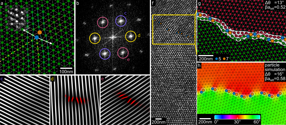 Figure 1
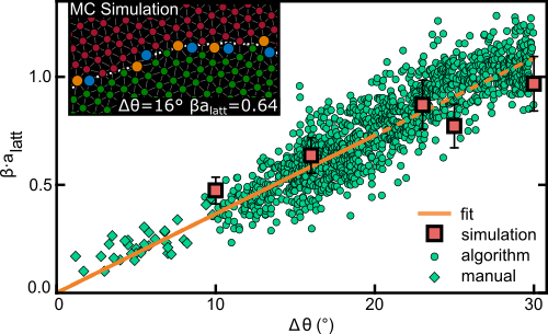 Figure 2
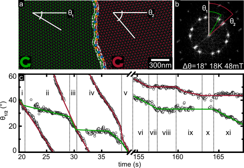 Figure 3
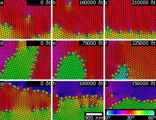 Figure 4
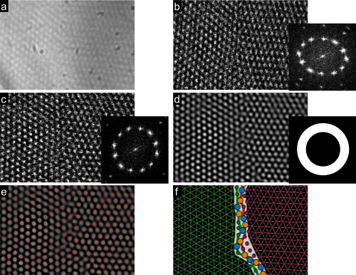 Figure 1
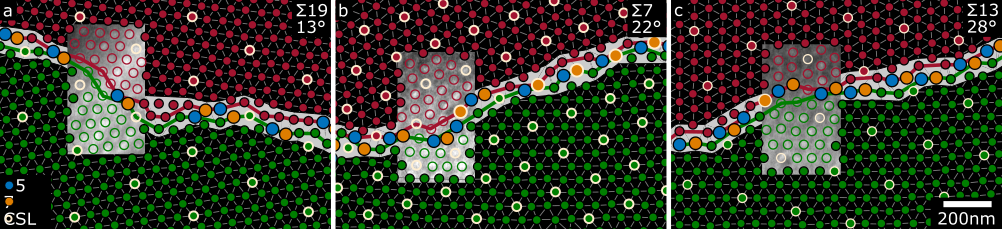 Figure 2
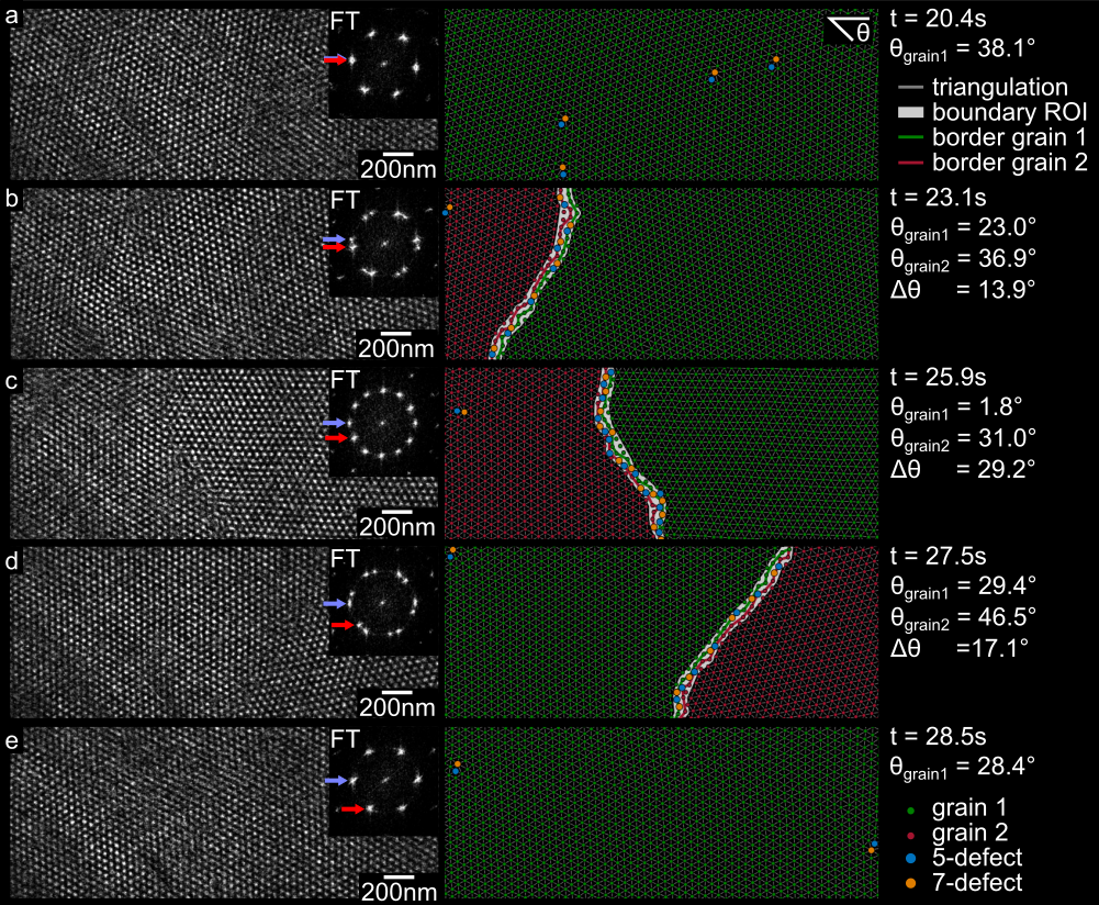 Figure 3
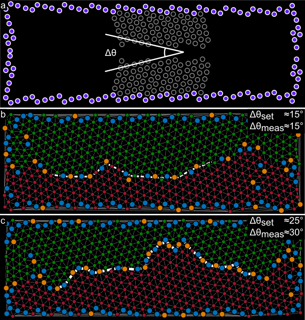 Figure 4
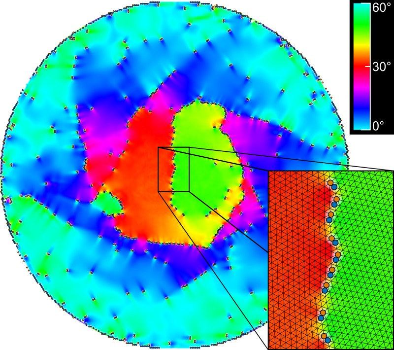 Figure 5
Peer Reviews
No public reviews on file for this paper yet. If you reviewed it on a platform where reviews are public (OpenReview, ICLR, NeurIPS, ICML), you can paste yours below so the community can read it here.
Videos
No videos yet. Explain this paper in a talk, walkthrough, or lecture? Add one.
Dynamical defects in rotating magnetic skyrmion lattices
S. Pöllath1, J. Wild1, L. Heinen2, T.N.G. Meier1, M. Kronseder1, L. Tutsch1, A. Bauer3, H. Berger4, C. Pfleiderer3, J. Zweck1, A. Rosch2, C.H. Back1
1 Institut für Experimentelle Physik, Universität Regensburg, Universitätsstr. 31, D-93040 Regensburg, Germany, 2 Institut für Theoretische Physik, Universität zu Köln, D-50937 Köln, Germany, 3 Physik-Department, Technische Universität München, D-85748 Garching, Germany, 4 Crystal Growth Facility, École Polytechnique Fédérale de Lausanne, CH-1015 Lausanne, Switzerland
Abstract
The chiral magnet Cu2OSeO3 hosts a skyrmion lattice, that may be equivalently described as a superposition of plane waves or lattice of particle-like topological objects. A thermal gradient may break up the skyrmion lattice and induce rotating domains raising the question which of these scenarios better describes the violent dynamics at the domain boundaries. Here we show that in an inhomogeneous temperature gradient caused by illumination in a Lorentz Transmission Electron Microscope different parts of the skyrmion lattice can be set into motion with different angular velocities. Tracking the time dependence we show that the constant rearrangement of domain walls is governed by dynamic 5-7 defects arranging into lines. An analysis of the associated defect density is described by Frank’s equation and agrees well with classical 2D-Monte Carlo simulations. Fluctuations of boundaries show surge-like rearrangement of skyrmion clusters driven by defect rearrangement consistent with simulations treating skyrmions as point particles. Our findings underline the particle character of the skyrmion.
In the last decade a non collinear topological spin texture, the skyrmion, has attracted great attention representing a new type of topological soliton in magnetic materials. Skyrmion lattices are periodic arrangements of a kind of magnetic whirls that may be found in a great variety of chiral magnets Bogdanov and Yablonskii (1989); Bogdanov and Huber (1994); Mühlbauer et al. (2009); Münzer et al. (2010); Pfleiderer et al. (2010); Yu et al. (2010, 2011); Seki et al. (2012a); Milde et al. (2013); Tokunaga et al. (2015); Nagaosa and Tokura (2013); Bauer and Pfleiderer (2016), as well as thin magnetic (multi-) layers Romming et al. (2013); Woo et al. (2016); Boulle et al. (2016); Moreau-Luchaire et al. (2016). The topology of skyrmions is encoded in a quantized winding number of the spin orientation. Emergent magnetic and electric fields describe the efficient coupling of the topological spin texture to electrons and magnons Neubauer et al. (2009); Jonietz et al. (2010); Schulz et al. (2012); Yu et al. (2012).
Skyrmion lattices may be described by two distinct approaches. In a wave-like picture as suggested e.g. by Small-Angle-Neutron Scattering (SANS) measurements, the skyrmionic crystal may be accounted for by a superposition of three spin helices with their propagation vector rotated by with respect to each other. From this point of view, the individual (solitonic) character of single skyrmions vanishes in the collective. Note that in most materials in the skyrmion lattice phase, higher order scattering is basically absent; for MnSi it is of the order of 10*-4* suggesting a rather smooth spin texture Adams et al. (2011). In contrast, in a particle-like picture skyrmions are viewed as individual solitonic particles. Indeed, individual skyrmions have been observed early on Yu et al. (2010); Romming et al. (2013) but the non-linear character as well as the degree of the particle-character in the skyrmion phase remained unresolved. In fact, recent studies reveal strong deformation of the precise shape of skyrmions under large strain Shibata et al. (2015).
The validity of either approach may be tested critically in studies of imperfect skyrmion lattices, alluding to similarities with well-known atomic lattices which also allows to verify particle conservation. In fact, the existence of defects and domains in skyrmion lattices has been reported Nagao et al. (2015); Rajeswari et al. (2015); Zhang et al. (2016a); Matsumoto et al. (2016), however, no comprehensive study focused on their dynamical properties has been performed, yet. Here, we use time resolved non-stroboscopic cryo-Lorentz transmission electron microscopy (L-TEM) to record domain boundaries and defects along with their fluctuations in the skyrmion lattice phase of mechanically thinned Cu2OSeO3 single crystals and find strong indications for the particle-like character of skyrmions in this material. We analyze the motion of single defects and of grain boundaries in the skyrmion lattice and perform a large statistical analysis of the defect density for a rich selection of misorientation angles between the skyrmion domains.
As our main result we find skyrmion domains with high mobility as well as simultaneous surge like rearrangement of many skyrmions triggered by magnon currents due to the temperature gradient introduced by the electron beam. The fluctuating domain boundaries may be described by a combination of 5-7 defects while the defect density increases with the misorientation angle between the grains. The observed domain boundaries are similar to 2D dense packed lattices of colloidal crystals, bubble rafts or even the nanonipple structure on the facet eyes of the morning cloak butterfly Irvine et al. (2012); Bragg and Nye (1947); Lee and Erb (2013) which is rather spectacular since the latter systems consist of solid particles while the skyrmion is a continuous spin texture.
Our findings are supported by 2D Monte Carlo simulations of the spin texture and by particle-based simulations of the dynamics. They allow insight into the nature of this peculiar lattice of topological spin objects and emphasize its particle-like character. Particle-like properties are important and desired since future spintronic applications aim at controlling single skyrmions Fert et al. (2013).
For our study we have selected the multiferroic insulator Cu2OSeO3, which is a prominent example for a bulk material hosting a skyrmionic crystal Seki et al. (2012b) as observed in reciprocal space using SANS Adams et al. (2012); Seki et al. (2012c); White et al. (2014) and X-ray magnetic scattering Langner et al. (2014); Zhang et al. (2016b, a) and in real space via L-TEM Seki et al. (2012a) and MFM Milde et al. (2016). Defects of the skyrmion phase of Cu2OSeO3 were reported first by Rajeswari et . Rajeswari et al. (2015) and Zhang et al. who studied a multi-domain state by resonant X-ray scattering Zhang et al. (2016a), however, without further details.
The Cu2OSeO3 single crystal was grown by the chemical vapor transport method and it was thinned in the direction first mechanically and then by argon-ion milling technique down to a thickness of . A few nanometers of carbon were evaporated onto the thinned sample to minimize charging effects. L-TEM images were taken with a Tecnai F30 TEM in Lorentz mode where the magnetic field normal to the sample surface is tuned by the objective lens current. A defocused image with the skyrmions is projected on a phosphorescence screen, recorded through a lead glass window by a digital camera with a maximum of 90 frames per second. We controlled the temperature of the sample with a Gatan liquid helium sample holder. All data shown here was recorded using a constant temperature and externally applied magnetic field of and . The phase diagram was entered by zero field cooling to and subsequently applying a magnetic field until the skyrmion lattice phase is present in the whole field of view.
In a perfect skyrmion lattice phase each skyrmion is surrounded by 6 neighbors, which does not hold when differently oriented skyrmion lattice domains are present. In our experiments and simulations we observe that the static and dynamic properties of domain boundaries are best described by 5-7 defects, i.e., two skyrmions which have five or seven nearest neighbors, respectively. The coordination number of the defects depends on the geometry of the magnetic lattice as can be seen from a comparison to recent investigations by Hagemeister et al. concerning defects in a skyrmion square lattice Hagemeister et al. (2016). A single 5-7 defect is shown in Figure 1a. The grey scale image in the upper left hand corner displays the raw L-TEM contrast after removal of image distortion, for details concerning image processing see Supplementary Material supplement .
The Delaunay triangulation method is used to identify nearest neighbors. A closer look reveals the true nature of this defect: two disclination lines (yellow dotted lines) join in the lattice node with five neighbors. Figures 1c-e show inverse Fourier-Transformations (FTs) of individual pairs of spots of the skyrmion lattice’s typical six spot FT pattern displayed in Figure 1b. The disclination lines can be identified directly as extra lines in Figures 1d,e ending at the defect position. Deformations (red color) occur predominantly perpendicular to the disclination lines. Figure 1c shows no significant deformation which means that the lattice along this third spin-crystallographic direction is not distorted. Note a slight lattice bending of around that is compensated by the 5-7 defect.
In the following we explore the possible particle-like character of skyrmions by analyzing the boundaries of domains in motion. When skyrmionic domains move, their constituents must rearrange which allows testing particle conservation. Early experiments Jonietz et al. (2010) showed that the combination of an electric current and thermal gradients can induce a rotation of the skyrmion lattice by finite angles Everschor et al. (2011, 2012). Continuous, ratchet-like motion induced by thermal gradients from the electron beam of a TEM was observed by Mochizuki et Mochizuki et al. (2014). The temperature gradient induced by the electron beam is not homogeneous leading to different effective torques at different positions of the sample and consequently causing parts of the skyrmion crystal to rotate at different angular velocities. Also homogeneous heat currents in combination with variations of the sample thickness can cause rotational torques Everschor et al. (2011, 2012). This eventually leads to domain formation and to heavy fluctuations of the domain boundaries, enabling us to record many different boundary configurations and tilt angle configurations.
Skyrmion crystallites with different lattice orientations require that defects form a grain boundary and the 5-7 defect is the disclination of choice for the skyrmionic lattice. For low tilt-angles between skyrmion crystallites single 5-7 defects line up to compose the boundary. Large angles () produce a boundary that mainly consists of strictly alternating nodes with coordination numbers 5 and 7.
Figure 1f shows a grain boundary for a tilt angle of , other examples are shown in the Supplementary Material supplement . The panel shows a processed image highlighting the two domains and their boundary region. The positions of individual skyrmions are marked as red and green dots, skyrmions with coordination number 5 (7) blue (orange). The grey rectangular area underneath parts of the processed data display the respective raw L-TEM image.
Importantly, we observe no preferred tilt angle in a statistical analysis of fluctuating domain walls that occupy many different configurations, see Fig. 2. Apparently the energy scale of a grain boundary as a function of misorientation angle is much smaller than the energy scales dominating the domain and defect motion Gottstein and Shvindlerman (2010). Furthermore, the skyrmion lattice is not pinned to the atomic crystal and freely floats on the sample.
The defect density along the border for the detected tilt-angles is shown in figure 2. In order to improve statistics for the analysis of defect densities along domain boundaries, an algorithm was developed that detects a potential lattice tilt by searching peaks in the histogram of nearest neighbor angles with respect to a fixed axis. Using this information it is possible to automatically detect the grain boundary and roughly measure its length, while manual measurements are necessary for low angles ().
In solid crystals Frank’s equation accounts for the spacing of individual defects in relation to the misorientation angle of grains and holds for symmetric small-angle grain boundaries Hirt and Lothe (1968). Provided that the length of the Burgers vector of the 5-7 defect is one skyrmion lattice constant , it can be rewritten as . A fit of the data to this equation in the range up to converges with and is in good agreement with the data. The dashed line is the extension of the fit to larger angles, where it still matches the data well.
To describe our findings taking into account the underlying spin texture, classical 2D Monte-Carlo Simulations were performed following Yu et al. (2010). The results of these simulations are shown in Figure 2. To maintain a boundary spins were fixed at the simulation grid’s edges forming starting points for two lattices that are tilted with respect to each other. Simulated annealing results in a grain boundary consisting of 5-7 defects in the grid’s center similar to our experimental observations. An example for a misorientation angle of 15∘ can be seen in the inset of Fig. 2. The line-defect-densities of these simulations were manually evaluated and also included in Fig. 2. Additional information can be found in the Supplementary Material supplement .
Observations of the boundaries’ dynamics show surge like rearrangement of Skyrmion clusters changing their affiliation to an individual domain between frames. Row shifts and small rotating groups of skyrmions can be seen as mechanisms of affiliation change. The skyrmion number during these fluctuations is conserved with an accuracy of 1 in the analyzable image sections, supporting the picture of single topological particles that rearrange. This strongly hints to topological charge conservation during the rearrangement processes.
The temporal evolution of the misorientation angle in Fig. 3 demonstrates the influence of the electron beam on two domains of the lattice. To visualize their dynamics we record a 170 s long movie using a frame rate of 30 fps. The sequence shown in the Supplementary Movie supplement ranges from about 20 s to 30 s. The left and right parts of Fig. 3c show the two angles of the rotating domains from 20 s to 40 s and from 155 s to 170 s, respectively. The angles and can consistently be obtained either from the real-space images or from its Fourier transform, see figures 3a,b. The evaluation of the first sequence reveals a fast rotation of one lattice (red) while the other (green) rotates much slower. It captures four full passes through all possible relative domain angles. For vanishing relative orientations (timespans i, iii,v) the domain wall dissolves and a unified lattice is obtained, i.e. there is no grain boundary or only single defects visible in the field of view.
The second sequence shows a different process. At first both grains rotate with almost the same velocities keeping the misorientation angle constant (vi). Next, one grain stops rotating leading to an increase of the net misorientation angle (vii). Before the maximum misorientation of is reached the other grain also stops (viii). During time span (ix) the inverse process of (vii) occurs, effectively reducing the misorientation angle. Now both grains stop (x) before one grain starts to move again (xi).
Note that the rotation direction during these processes remains mainly fixed in counter clockwise direction in accordance with the findings of reference Mochizuki et al. (2014). However, slight deviations of this strict sense of rotation are observed for instance in region (vii), which we verified by raw data. This rotation in opposite direction can be interpreted as gearwheel rotation of both lattices. The relative angular speed varies from [math] to . The different behavior of the two sequences indicates that the effective rotational torques are substantially larger during the first sequence compared to the second sequence. As the temperature gradients are expected to be approximately constant in time, this arises very likely from changes in the size of the domains and therefore in the total effective forces at the domain boundary. Indeed, indicated by a tilt of the orientation of the grain boundary, the relative domain sizes changed in between the two sequences.
The topological protection of skyrmions, the associated approximate conservation of skyrmion number observed in our experiment and the dominance of 5-7 defects suggest that skyrmions should be viewed as discrete particles even in lattice textures. To corroborate this picture we have performed simulations of large rotating skyrmion lattices and track the motion of skyrmions treated as individual particles Lin et al. (2013) arranged on a disk, see Supplementary Material supplement . Even for this simplified approach it is not possible to simulate directly the experimentally relevant time scales of tens of seconds which is a factor larger than the microscopic time scale for typical excitations of the skyrmion lattice Schwarze et al. (2015). Remarkably, we are, however, able to reproduce qualitatively the experimentally observed dynamics using current densities much larger than in the experiment.
Under the shear stress arising from the current pattern, domains characterized by different rotational angle form. Most importantly, the simulations show the dynamical formation of domain walls consisting of 5-7 defects similar to our experimental observations, see Fig. 1g and 4. The domain dynamics is a highly dynamic process characterized by continuous creation and destruction of domains. Within our simulation the rapid motion of single 5-7 defects is a dominating mechanism for the change of defect density, and thus the relative rotation of domains. We observe strongly fluctuating domain sizes, domain mergers and surge-like rearrangements of domains in our simulations, see Fig. 4. The Supplementary Movie gives an overview of the dynamical, highly non-linear processes which accompany the rotation of the domainssupplement .
In summary, we observe extraordinary dynamics of rotating skyrmion domains while exposed to a temperature induced torque. The dynamics are largely dominated by the motion and rearrangement of 5-7 defects, whose density at domain walls has to adjust to the continuously changing misorientation angle of neighboring domains. The domain boundary shows heavy fluctuations but ultimately allows for a continuous net rotation of individual domains driven by the applied torques. Our findings support the skyrmion’s particle-like character in the material Cu2OSeO3. The particle-like character of skyrmions is evidenced by the existence of 5-7 defects, the correspondence of the defect density along the grain boundary with classical particle theory and the particle-like rearrangement mechanisms during grain boundary fluctuations. Furthermore external manipulation of individual skyrmion grains is possible by applying a temperature gradient.
.1 Supplement 1: Image processing
To detect skyrmion positions advanced image processing of the data is necessary. First the raw sequence of images (Fig. 5a) is referenced to compensate image drifts. Subsequently background needs to be removed. For this the average intensity of a video sequence of approximately three seconds is taken. Due to its fast rotation the magnetic contrast of the skyrmion lattice averages to a constant value while the image background remains unchanged. After subtraction (Fig. 5b), distortion of the image is compensated. This distortion originates from the measurement technique of recording a phosphorescent screen which is located inside the transmission electron microscope (TEM) so that it is canted with respect to the incident electron beam. The distortion can be seen in the Fourier transformation (inset Fig. 5b) as a canted ellipse of the typical six spot pattern. To get rid of this distortion the image is rotated such that the main axes of the ellipse lie parallel to the rectangular pixel grid and then scaled to best possibly reduce the ellipticity of the regularly round spot pattern (cross-checked using undistorted images obtained via the built-in CCD camera). The undistorted image and the round FFT spot pattern can be seen in Fig. 5c. To enhance the signal-to-noise ratio further the images are bandpass filtered (Fig. 5d, filter in the inset). Next the skyrmion positions are detected using a local maximum finding algorithm (Fig. 5e). Finally Delaunay triangulation can be used to detect nearest neighbors and from that grains, grain boundaries, misorientation angles and defects in the skyrmion lattice (Fig. 5f).
.2 Supplement 2: Examples for CSL grain boundary configurations
As mentioned in the main text, many different grain boundary configurations were recorded. Fig. 6 shows a selection of grain boundaries for tilt angles of , and . The panels show processed images highlighting the two crystallites and their boundary region. Here, the positions of the individual skyrmions are encoded as red and green dots in the two crystallites. A region of interest for the boundary is shown in grey and skyrmions with coordination number 5 (7) in blue (orange). Red and green lines are the estimated boundaries. Grey rectangular areas underneath parts of the processed data show the raw distortion compensated L-TEM images. As can be seen in the images, the defect density rises as a function of tilt-angle. Furthermore, the boundary is not straight but shows meander-like progression. For the three examples shown in Fig. 6 we also show the corresponding CSL-lattices (white rings around the positions of the skyrmions) revealing the -values of these special boundaries as the ratio of the superlattice shared by both grains to the common lattice unit cell volume. We find that the shown grain boundaries can be described by (a) -19, (b) -7 and (c) -13.
.3 Supplement 3: Capturing the dynamics of a grain boundary under grain rotation
A movie is presented to demonstrate the magnon-current driven rotation of the skyrmion grains. In the video the two grains rotate with different angular velocities leading to an increase of misorientation angle from up to and a subsequent decrease to . Fig. 7 shows five still images of the video. Each panel contains background subtracted data on the left with the respective Fourier transformation in an inset and the processed data on the right. Note that in Fig. 7 as well as the movie, 5-7 defects next to the grain boundary were marked manually while omitting possible defects that were detected from the algorithm but are located inside blurred regions of the raw data. Further given are time and grain orientation angles. The sequence starts with a nearly perfect hexagonal skyrmion lattice with few 5-7 defects present (Fig. 7a). A clear grain boundary forms and the misorientation angle increases to (Fig. 7b,c). Note the separating spots in the respective FT images. Finally the misorientation angle decreases again (Fig. 7d) until the misorientation approaches and there is no grain boundary visible inside the field of view (Fig. 7e).
.4 Supplement 4: Monte Carlo Simulations
For the Classical Monte Carlo simulations we follow the work of Tokura et. Yu et al. (2010). Simulated annealing was used to relax Heisenberg spins on a 2d-plane (-) using a single flip Metropolis algorithm with the lattice Hamiltonian Yu et al. (2010)
[TABLE]
Here ferromagnetic exchange , Dzyaloshinskii-Moriya interaction and Zeeman coupling to an external magnetic field are considered. Discretization takes place on a 2D square lattice with lattice sites lattice constant along the base vectors and . The spins were restricted to a unit sphere such that .
First for fixed parameters and a temperature-field phase diagram is obtained by gradually lowering with a relaxation time of lattice sweeps between temperature steps on a 30x30 lattice with periodic boundary conditions until . This supplies the information of suitable field values for a skyrmion lattice ground state. The ratio of and was chosen such that the spiral propagation length is 10 lattice sites.
The simulation grid is then extended to a 360x120 lattice with open boundary conditions. Single spins near the long edges are fixed antiparallel to the applied external field in -direction. The fixed spins are chosen such that they make up a hexagonal lattice with a lattice constant measured from the skyrmion lattice of previous simulations. This artificial lattice is however tilted for opposing long grid edges in order to simulate any desired misorientation angle . An example can be seen in Fig. 8a. The purple dots show the actual position of single fixed spins while the white dashed rings are an extension to show the lattice that is expected to form.
As before simulated annealing is used to determine the ground state while applying an external magnetic field at which skyrmions are expected to occur from the phase diagram obtained before. Indeed, skyrmions are established around almost all of the fixed spins. Fig. 8b,c shows two examples of relaxed ground states for set misorientation and . In the center of the grid where no spins are fixed the two grains in fact form a grain boundary comprising the defects described in the main text. Towards the short grid edges the clear boundary is lost which is due to the proximity to the border and formation of small additional grains. For larger misorientation angles the simulation does not exactly follow the configured tilt (e.g. results in in Fig. 8c) which may be due to the fact that lateral movement of the grains is permitted by the fixed lattice positions. For these cases the measured misorientation was used for the defect density evaluation of the main text.
.5 Supplement 5: Particle-based simulation and rotational dynamics
To model the formation and dynamics of rotating skyrmion lattices we treat each skyrmion as an individual classical particle with coordinates . Compared to direct micromagnetic simulations of spins this allows to treat much larger systems and longer time scales, speeding up simulations by more than 2 orders of magnitude. Furthermore, it allows us to find out whether a particle-based model correctly reproduces the experimental finding. In our simulations we model particles arranged on a disk. Even for this simplified approach it is not possible to simulate directly the experimentally relevant time scales of tens of seconds which is a factor larger than the microscopic time scale for typical excitations of the skyrmion lattice Schwarze et al. (2015). Remarkably, we are, however, able to reproduce qualitatively the experimentally observed dynamics using current densities much larger than in the experiment, see below. The equations of motion are given by
[TABLE]
and solved by a straightforward Runge-Kutta approach. The dynamics of the skyrmions is dominated by the strong gyrocoupling which is fixed by the topology of the skyrmions, , where is the two-dimensional spin density. The damping constant is much weaker, using we set in our simulations. The terms proportional to models the coupling of the skyrmion to heat currents Schroeter et al. and describes the velocity of spin-currents induced by the heat currents. We assume a Gaussian beam profile and use the two-dimensional continuity equation to determine the corresponding heat current profile. Using that is proportional to the heat current we obtain . Note that is oriented towards the center reflecting that a single skyrmion tends to move towards a heat source Kong and Zang (2013); Schütte and Garst (2014); Nagaosa and Tokura (2013); Schroeter et al. . Theoretical calculations Schroeter et al. suggest that is negative, much larger than , but smaller than . We set for our calculation but have checked that qualitatively similar results are obtained for .
The skyrmion-skyrmion interaction is calculated by using a fit to skyrmion-skyrmion potential which we obtained from micromagnetic simulations. We use with within our unit system and set , equilibrium skyrmion distance , , for the simulation shown in the Supplementary Movie. The value for was extracted from the micromagnetic simulation of a single skyrmion, from the simulation of a skyrmion lattice and is a fit to a simulation of two skyrmions. All of these simulations were performed at in our units. Fig. 9 shows the result of such an analysis.
We initialize our system on a perfect, defect-free hexagonal skyrmion lattice and fix the position of the particles at the circumference of radius , much larger than the typical diameter of the rotating domains in the center of the simulation. This disorder-free, high-symmetry situation allows to investigate the dynamics of domain formation in an idealized setup where pinning fixes the skyrmion lattice in the far distance while circular heat currents induce a rotation in the central part. As in the analysis of the experiment we perform Delaunay triangulation to identify lattice defects and calculate lattice orientation. Fig. 9 shows the result of such an analysis.
Our simulations nicely reproduce that, under the shear stress arising from the current pattern, domains characterized by different rotational angle form. As in the experiment, they are separated by sharp domain walls characterized by the accumulation of 5-7 defects on the domain boundary, see Fig. 9. Even for our idealized high-symmetry setup, the domain dynamics is a highly dynamic process characterized by continuous creation and destruction of domains. Whenever neighboring domains rotate with different angular velocities, the density of defects at the domain walls has to change as discussed in the main text. Often far from the domain wall pairs of 5-7 defects are created and move with high speed relaxing the overall strain in the driven system. We believe that this motion is often too fast to be resolved in our experiments but in our simulation the motion of individual 5-7 defects is clearly a dominant mechanism for the dynamics of the whole system. The defects tend to align into domain walls, as discussed. The influx of such defects can increase the defect density or reduce it when defects with opposite Burgers vectors annihilate. The supplementary movie gives an overview of the dynamical, highly non-linear processes which accompany the rotation of the domains. Fig. 4 of the main text shows examplarily how defect motion and defect annihilation determines the domain wall dynamics.
Our experimental observations and simulations have to be distinguished from alternative scenarios for domain rotation. For example, one can envision a situation where crystalline domains rotating with different velocities are separated by a liquid region. For such a case domains can be stable and domain walls can be stationary. No large-distance defect motion or domain wall rearrangement is required. In contrast we find that the dynamics of the system is dominated by just such processes.
The reference list from the paper itself. Each links out to its DOI / PubMed record.
- 1Bogdanov and Yablonskii (1989) A. Bogdanov and D. Yablonskii, Zh. Eksp. Teo. Fiz. 95 , 178 (1989).
- 2Bogdanov and Huber (1994) A. Bogdanov and A. Huber, J. Magn. Magn. Mat. 138 , 255–269 (1994).
- 3Mühlbauer et al. (2009) S. Mühlbauer, B. Binz, F. Jonietz, C. Pfleiderer, A. Rosch, A. Neubauer, R. Georgii, and P. Böni, Science 323 , 915 (2009) . · doi ↗
- 4Münzer et al. (2010) W. Münzer, A. Neubauer, T. Adams, S. Mühlbauer, C. Franz, F. Jonietz, R. Georgii, P. Böni, B. Pedersen, M. Schmidt, A. Rosch, and C. Pfleiderer, Phys. Rev. B 81 , 041203 (R) (2010) . · doi ↗
- 5Pfleiderer et al. (2010) C. Pfleiderer, T. Adams, A. Bauer, W. Biberacher, B. Binz, F. Birkelbach, P. Böni, C. Franz, R. Georgii, M. Janoschek, F. Jonietz, T. Keller, R. Ritz, S. Mühlbauer, W. Münzer, A. Neubauer, B. Pedersen, and A. Rosch, J. Phys.: Condens. Matter 22 , 164207 (2010) . · doi ↗
- 6Yu et al. (2010) X. Z. Yu, Y. Onose, N. Kanazawa, J. H. Park, J. H. Han, Y. Matsui, N. Nagaosa, and Y. Tokura, Nature (London) 465 , 901 (2010) . · doi ↗
- 7Yu et al. (2011) X. Z. Yu, N. Kanazawa, Y. Onose, K. Kimoto, W. Z. Zhang, S. Ishiwata, Y. Matsui, and Y. Tokura, Nature Mater. 10 , 106 (2011) . · doi ↗
- 8Seki et al. (2012 a) S. Seki, X. Z. Yu, S. Ishiwata, and Y. Tokura, Science 336 , 198 (2012 a) . · doi ↗