Automated Analysis of Multi-View Software Architectures
Chih-Hong Cheng, Yassine Hamza, Harald Ruess

TL;DR
This paper presents a method to formally validate multi-view software architectures early in development by constructing a unified model in Promela, enabling model checking and debugging of architectural models.
Contribution
It introduces a novel approach to fuse UML diagrams into a single formal model for early validation of multi-view architectures.
Findings
Successfully implemented as a plugin for Enterprise Architect.
Used SPIN model checker to identify corner cases in industrial models.
Demonstrated effectiveness in debugging multi-view architectural models.
Abstract
Software architectures usually are comprised of different views for capturing static, runtime, and deployment aspects. What is currently missing, however, are formal validation and verification techniques of multi-view architecture in very early phases of the software development lifecycle. The main contribution of this paper therefore is the construction of a single formal model (in Promela) for certain stylized, and widely used, multi-view architectures by suitably interpreting and fusing sub-models from different UML diagrams. Possible counter-examples produced by model checking are fed back as test scenarios for debugging the multi-view architectural model. We have implemented this algorithm as a plug-in for the Enterprise Architect development tool, and successfully used SPIN model checking for debugging some industrial architectural multi-view models by identifying a number of…
Click any figure to enlarge with its caption.
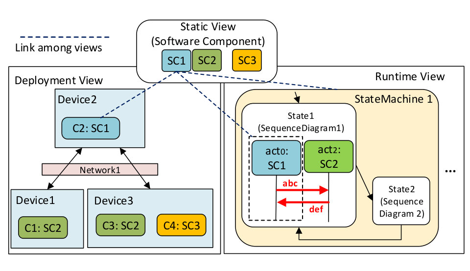 Figure 1
| Elements | Meaning | Corresponding Promela construct |
|---|---|---|
|
Messages
|
Set of message with contents | mtype = {abc, def}; |
|
chan1
|
Synchronous channel | chan chan1 = [0] of mtype; |
|
chan2[3]
|
Asynchronous channel named chan2 with buffer size 3 | chan chan2 = [3] of mtype; |
| Action | Program label ”S3”, move to next action in the process | S3: |
| Action | Non-deterministically jump to label S3 or S4 |
int i;
select (i : 0..1); if :: i != 1 -> goto S3 :: i == 1 -> goto S4 fi; |
| Action | Send message abc to channel chan1 | chan1 !abc; |
| Action | Receive message def from channel chan2 | chan2 ?def; |
| Under-specification scenarios | Mitigation strategies |
|---|---|
| In the deployment view, allow components within a device to communicate with each other? | Allow / Disallow / Trigger the designer for actions |
| Operation over variables both in a state of a state-machine diagram and in the refinement sequence diagram of that state? | Variable operations over variables in a state should appear {before, after} actions in sequence diagram |
| Unclear requirement in communication buffer size, for asyn. communication? | Use pre-defined value / Trigger the designer for actions |
| An actor sends to one entity in the sequence diagram, while multiple receivers exists in the deployment view? | Send to all entities / Send to one randomly selected entity / Trigger exception |
Peer Reviews
No public reviews on file for this paper yet. If you reviewed it on a platform where reviews are public (OpenReview, ICLR, NeurIPS, ICML), you can paste yours below so the community can read it here.
Videos
No videos yet. Explain this paper in a talk, walkthrough, or lecture? Add one.
Taxonomy
TopicsAdvanced Software Engineering Methodologies · Formal Methods in Verification · Model-Driven Software Engineering Techniques
Automated Analysis of Multi-View Software Architectures
Chih-Hong Cheng
fortiss GmbHMunichGermany
,
Yassine Hamza
Technische Universität MünchenMunichGermany
and
Harald Ruess
fortiss GmbHMunichGermany
Abstract.
Software architectures usually are comprised of different views for capturing static, runtime, and deployment aspects. What is currently missing, however, are formal validation and verification techniques of multi-view architecture in very early phases of the software development lifecycle. The main contribution of this paper therefore is the construction of a single formal model (in Promela) for certain stylized, and widely used, multi-view architectures by suitably interpreting and fusing sub-models from different UML diagrams. Possible counter-examples produced by model checking are fed back as test scenarios for debugging the multi-view architectural model. We have implemented this algorithm as a plug-in for the Enterprise Architect development tool, and successfully used SPIN model checking for debugging some industrial architectural multi-view models by identifying a number of undesirable corner cases.
multi-view architecture analysis, SPIN model checker
1. Introduction
Software architectures usually are comprised of different views for capturing static, runtime, and deployment aspects (arc42, ; bass2007software, ). The static/component view describes the logical decomposition of the system into building blocks (e.g., packages, components, classes), whereas the runtime view describes the behavior and interaction of the building blocks as runtime elements in the running system, using diagrams such as sequence diagrams, activity diagrams, or state machines, and the deployment view shows how software is assigned to hardware processing and communication elements.
In the current state-of-the-practice, architectural models are analyzed in early phases in the software development cycle, mainly by means of manual and resource-intensive review frameworks such as the Architectural Trade-off Analysis Method (ATAM) (bass2007software, ). What is currently missing, however, are formal analysis techniques of multi-view architectures for early and automated detection of, say, unwanted behavior due to under-specification.
In this paper, we therefore reconstruct a single model of a multi-view architecture, which is suitable for formal analysis, by fusing sub-models of different views in UML diagrams (rumbaugh2004unified, ), as provided, for example in architectural development tools such as Enterprise Architect. Our fusion algorithm proceeds by taking deployment views as skeletons to offer basic communication structure over processes and channels in the actual system. The concrete behavior of each deployed software component — as documented in the static view — is captured by run-time views. One notable challenge is to cope with under-specification among views, as dynamic architectural views often only capture certain scenarios but not the complete component behavior and all possible interactions. To this end, semantic extrapolation is needed for constructing a model-checkable verification model and we enumerate possible extrapolation strategies.
We have implemented our fusion algorithm as a plug-in for Enterprise Architect (EA). This plug-in generates verification models in the Promela language, which are used as inputs to the SPIN model checker (holzmann2004spin, ). Counter-examples generated by the model-checkers are used as test cases for debugging the multi-view architectural model. We evaluated this EA plug-in in early phases of developing two mission-critical distributed software systems in industrial projects, and successfully identified undesired corner cases due to under-specification in the model.
(Related work) There is a rich literature on the verification of UML-like diagrams. For example, refinement of activity diagrams has been based on LTL model checking (muram2014automated, ), and state machine diagrams have been translated to hierarchical automata as the basis for model checking (schafer2001model, ; niewiadomski2009towards, ; liu2013formal, ). Moreover, sequence diagrams have a straightforward correspondence to communicating processes and process algebras (ait_oubelli2011uml, ; lima2009formal, ; sieverding2013sequence, ). Use case diagrams can be checked for consistency or containment by means of viewing them as programs with constraints (klimek2010formal, ) or by a translation into activity diagrams (kosters2001validation, ). Lastly, using annotations such as UML Marte profile (gerard2008uml, ), one may verify extra-functional properties such as timing (Louati2015, ). In contrast to these approaches we are analyzing multi-view architectural models, which include static, runtime, and deployment views, being restricted to a certain stylized use and linking between views. We therefore do not address or even try to solve the general multi-view consistency problem for UML (knapp2016multi, ).
2. Multi-view Software Architecture and View Linking
Using architectural development tools such as Enterprise Architect (EA), the designer may maintain links among multiple views by creating components in the static view, by building runtime and deployment view using components in the static view, and by associating each diagram with a component or a sub-structure.
Figure 1 illustrates these concepts using a simple architectural example.111 For the example in Figure 1, a model in Enterprise Architect (freely available for model viewing) which maintains such symbolic links can be downloaded at https://www.dropbox.com/s/hg8jiddxh6rs5xs/NFM_Model.eap. We also refer readers to https://youtu.be/9Mg_2UH5vDM for a video showing how the link of views are maintained under Enterprise Architect, together with how our prototypical tool automatically generates verification models in Promela form.
There are three software components SC1, SC2, and SC3 in the static view. In the deployment view, three devices Device1, Device2, Device3 are included in the final deployed system, where for each device, the underlying software components are created (using drag-and-drop in EA) as an instantiation of components in the static view. For example, for the Device2 in Figure 1, C2 is an instance of the software component SC1 from the static view.
For each software component in the static view there is a state machine or activity diagram in the behavioral view, where each of the states provides behavioral scenarios for different execution modes (for example, normal and error modes). Behavior and interaction in each state (or mode) are expressed in terms of scenarios expressed as sequence diagrams. In Figure 1, for example the behavior of component SC1 is refined to StateMachine1, where internally, State1 is further refined into SequenceDiagram1. Notice also that in SequenceDiagram1, the actor is surrounded by a dashed component. This is often used in UML modeling as a modeling trick to capture system boundary. Such a boundary allows modeling the interaction of multiple instantiations of the same component, as commonly seen in fault-tolerant systems where redundancy and distributed voting are applied.
We are now providing a formal signature for these multi-view architectural concepts; hereby, is used to denote the projection of A with respect to B. A multi-view architectural model Arch is a triple . ComponentView consists of set of software components where can again be refined to a set of components; for expressing, for example, a ”uses” structure. For the purposes of this paper, such a hierarchical component view can always considered to be in flattened form. The DeploymentView is a pair of sets. First, every device is a set itself of instantiated software components, and for every is of type where . We use to denote the typing information. Second, pairs of devices , where , are interpreted as directed (from left-to-right) edges between devices. Finally, the RuntimeView is a quadruple .
- •
StateMachines is the set of state machines with each element having a set of states , an initial state and the set of transitions . We use to denote a state s in state machine .
- •
SequenceDiagrams is the set of sequence diagrams. Again for simplifying formulation, let elements in sequence diagrams be variable-free, straight-line (i.e., no if-else or while) programs. An element is a tuple , where Act is the set of actors and is the one that is in the system boundary (cf. act0 in Figure 1). Each actor is a tuple where indicates the typing of the actor by referencing the element in component view, and Msg is the finite concatenation of messages , where forall , . In message , indicates if the message is being sent () or received (), indicates synchronous/asynchronous message passing, is used to capture all possible message contents, and the last item is the entity being communicated. Consider act0 in Figure 1, it is represented as .
- •
maps an element in ComponentView to a state machine in StateMachines. For the example in Figure 1,
.
- •
maps a state in a state machine to zero or one sequence diagram, where if and if for state in state machine we have , then . For the example in Figure 1,
.
3. Multi-View Fusion
Based on signatures for multi-view architectural models as defined above, we are now describing the process of providing a behavioral semantics based on fusing multiple views. A verification model is a triple , where Messages is the set of messages, Channels is the set of (synchronous or asynchronous-with-fixed-buffer) channels, and Processes is a set of processes. Hereby, each process Process is a sequence of atomic actions, including labels, non-deterministic goto primitives, and message send/receive. The semantics of a verification model is based on Promela (holzmann2004spin, ). For the purpose of reference, however, we are listing some correspondence of constructs in the architectural model and corresponding verification models in Table 1.
Now, the workflow presented in Algorithm 1 translates a multi-view architecture into a formal verification model. For ease of explanation assume all message passing to be synchronous for now. Lines 1 and 2 in Algorithm 1 collect all messages by scanning all actors in the given sequence diagrams. Next, lines 3 and 4 define device-to-device channels by scanning through the given network element, and lines 5 and 6 define point-to-point channels within a device. Lines 7 to 11 start instantiating processes for every deployed software component in the deployment view, where the process starts by moving to the initial state (line 10). The for-loop in Line 11 traverses through the state-machine diagram, establishes a label for entry (line 12), and creates outgoing transitions to successor states (line 21). Internally, the algorithm jumps to the corresponding sequence diagram (line 13), and tries to parse each message being sent or received (line 14) into the corresponding channel (line 16-20), where, by probing the deployment view, messages are communicated in the internal channel if the source and destination components are located in the same device (line 16, 19). Otherwise, intra-device channels are used for communication (line 17, 20). Notice that the algorithm simply communicates with all the components having the same type, provided that they are supported by the communication architecture in the deployment view. This provides the basis for the so-called extrapolation in standard UML semantics, as discussed below.
For the example in Figure 1, we use the generated verification model in Figure 2 to explain the concept, where comments in Figure 2 indicates corresponding actions done in Algorithm 1. Notice that the presentation of the translation algorithm is simplified in that it does not support variables, branches and loops. These kinds of extensions are straightforward and are also supported in our prototype implementation.
Most interestingly, lines 16-20 in Figure 1 make various assumptions about the architectural model under consideration, and semantic extrapolation is used to determine choices being made during the translation. Such a semantic extrapolation, due to lack of proper semantics in (combining) UML and sometimes due to underspecification in modeling, can be explicitly stated and controlled. Table 2 enumerates some important cases and corresponding strategies for semantic extrapolation in order to complete translation.
4. Evaluation and Concluding Remarks
We have implemented a plug-in for the Enterprise Architect development tool based on the presented translation. We summarize our findings on using this tool in the architectural design and analysis for two industrial developments.
- •
The first case study is a modular adaptive automotive runtime environment. Since this platform has been designed to be fault-tolerant, we annotate possible faults in the deployment view, such as power-outage of a device (fail silent) or lost communication messages. Our tool translates these faults annotation by non-deterministically injecting faults into the generated verification model. In one deployment scenario, a counter-example generated by the SPIN model checker demonstrates that the overall system does not function correctly whenever there are certain faults during start-up, thereby preventing consensus to be reached between computing nodes.
- •
Our second case study is a control automation architecture based on the concept of micro-services and a cloud platform. Again, test cases as generated from SPIN model checking of the fused Promela model were instrumental in debugging and improving the design at an early phase in the development.
On the other hand, we have also been experiencing a number of ”automation surprises” due to implicit assumptions on the architecture and the generated fused model. For example, the fused model does not capture the fact that service handlers may be viewed as a non-terminating while-loop program that can handle various requests using switch statements, even though (at least) some designers made such an implicit assumption. These kinds of automation surprises might be hard to avoid when applying formal analysis to architectural notations with ambiguous semantics.
It would be most interesting to specify some of the encodings presented here also in a theorem proving environment such as PVS, and to experimentally compare the proposed semantic extrapolation of the behavior of architectural designs with logic- and constraint-based approaches for partially specified systems.
The reference list from the paper itself. Each links out to its DOI / PubMed record.
- 1[1] The Arc 42 portal: http://www.arc 42.com .
- 2[2] Enterprise architect: http://www.sparxsystems.com.au/ .
- 3[3] M. Ait_Oubelli, N. Younsi, A. Amirat, and A. Menasria. From UML 2.0 sequence diagrams to Promela code by graph transformation using Atom 3. In: CIIA , 2011.
- 4[4] L. Bass, P. Clenents, and R. Kazman. Software architecture in practice, 3rd edition . Pearson Education, 2011.
- 5[5] S. Gérard and B. Selic. The UML-Marte standardized profile. IFAC Proceedings Volumes , 41(2):6909–6913, 2008.
- 6[6] G. J. Holzmann. The SPIN model checker: Primer and reference manual . Addison-Wesley, 2004.
- 7[7] R. Klimek and P. Szwed. Formal analysis of use case diagrams. In: Computer Science , 11:115–131, 2010.
- 8[8] G. Kösters, H.-W. Six, and M. Winter. Validation and verification of use cases and class models. In: REFSQ , 2001.