Resolution-Adaptive Hybrid MIMO Architectures for Millimeter Wave Communications
Jinseok Choi, Brian L. Evans, and Alan Gatherer

TL;DR
This paper introduces a resolution-adaptive hybrid MIMO architecture with novel ADC bit-allocation algorithms for mmWave receivers, enhancing spectral and energy efficiency by optimizing ADC resolution based on channel conditions.
Contribution
It proposes new ADC bit-allocation algorithms, capacity approximation methods, and a worst-case ergodic rate analysis for hybrid MIMO systems with adaptive ADC resolution.
Findings
BA algorithms outperform fixed-ADC in spectral efficiency
Achieve 22% better energy efficiency with negligible quantization error
Capacity and ergodic rate formulas validated by simulations
Abstract
In this paper, we propose a hybrid analog-digital beamforming architecture with resolution-adaptive ADCs for millimeter wave (mmWave) receivers with large antenna arrays. We adopt array response vectors for the analog combiners and derive ADC bit-allocation (BA) solutions in closed form. The BA solutions reveal that the optimal number of ADC bits is logarithmically proportional to the RF chain's signal-to-noise ratio raised to the 1/3 power. Using the solutions, two proposed BA algorithms minimize the mean square quantization error of received analog signals under a total ADC power constraint. Contributions of this paper include 1) ADC bit-allocation algorithms to improve communication performance of a hybrid MIMO receiver, 2) approximation of the capacity with the BA algorithm as a function of channels, and 3) a worst-case analysis of the ergodic rate of the proposed MIMO receiver that…
Click any figure to enlarge with its caption.
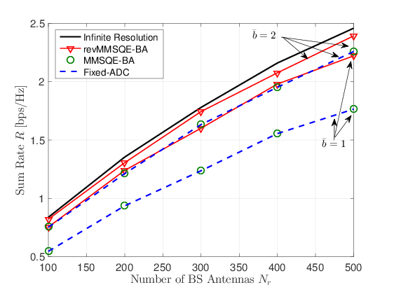 Figure 1
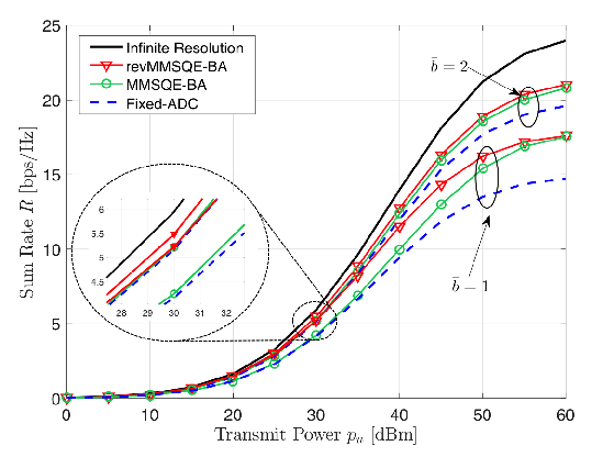 Figure 2
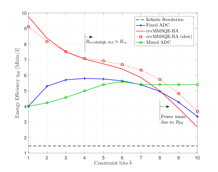 Figure 3
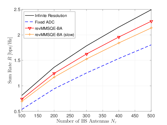 Figure 4
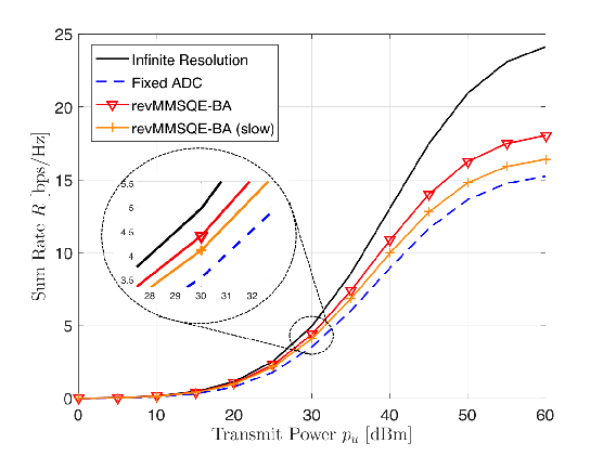 Figure 5
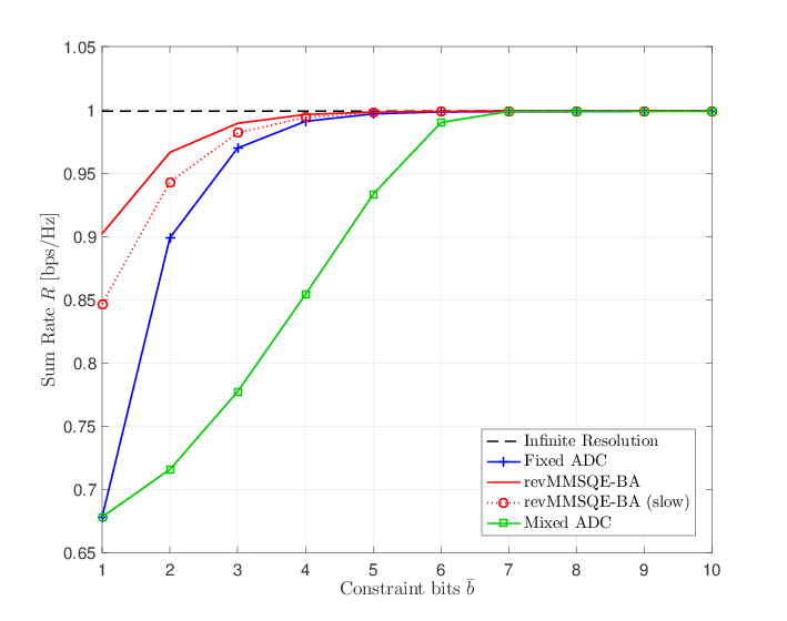 Figure 6
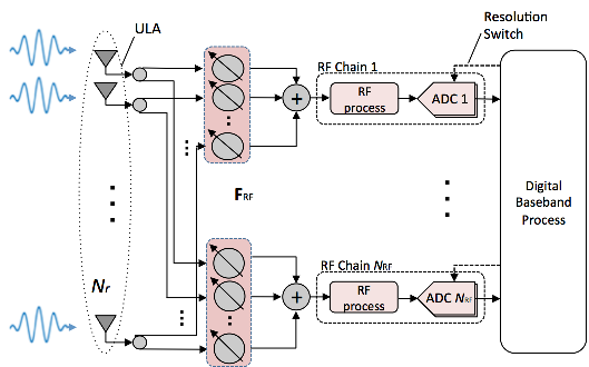 Figure 7
 Figure 8
 Figure 9
 Figure 10
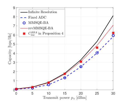 Figure 11
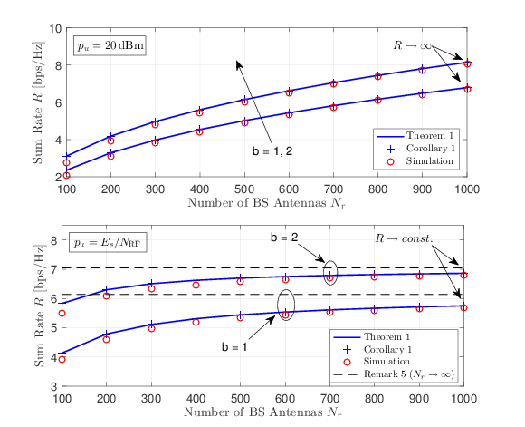 Figure 12
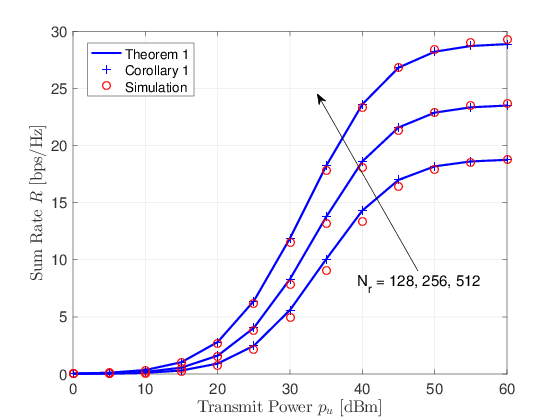 Figure 13
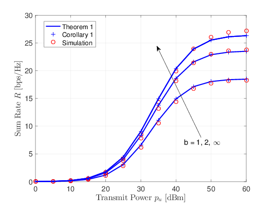 Figure 14
| 1 | 2 | 3 | 4 | 5 | |
|---|---|---|---|---|---|
| 0.3634 | 0.1175 | 0.03454 | 0.009497 | 0.002499 | |
| Constraint | ADC Resolutions (bits) | ||||||
|---|---|---|---|---|---|---|---|
| Bits | 0 | 1 | 2 | 3 | 4 | 5 | 6 |
| 40.78 | 28.20 | 26.46 | 4.46 | 0.10 | 0 | 0 | |
| 32.10 | 16.32 | 25.54 | 19.36 | 6.54 | 0.14 | 0 | |
| 19.40 | 7.46 | 18.42 | 28.54 | 22.58 | 3.48 | 0.12 | |
Peer Reviews
No public reviews on file for this paper yet. If you reviewed it on a platform where reviews are public (OpenReview, ICLR, NeurIPS, ICML), you can paste yours below so the community can read it here.
Videos
No videos yet. Explain this paper in a talk, walkthrough, or lecture? Add one.
Resolution-Adaptive Hybrid MIMO Architectures
for Millimeter Wave Communications
Jinseok Choi, Brian L. Evans, and Alan Gatherer
J. Choi and B. L. Evans are with the Wireless Networking and Communication Group(WNCG), Department of Electrical and Computer Engineering, The Universityof Texas at Austin, Austin, TX 78701 USA. (e-mail: [email protected], [email protected]). A. Gatherer is with Wireless Access Lab., Huawei Technologies, Legacy Dr, Plano, TX 75024 USA. (e-mail: [email protected]). The authors at The University of Texas at Austin were supported by gift funding from Huawei Technologies.
Abstract
In this paper, we propose a hybrid analog-digital beamforming architecture with resolution-adaptive ADCs for millimeter wave (mmWave) receivers with large antenna arrays. We adopt array response vectors for the analog combiners and derive ADC bit-allocation (BA) solutions in closed form. The BA solutions reveal that the optimal number of ADC bits is logarithmically proportional to the RF chain’s signal-to-noise ratio raised to the power. Using the solutions, two proposed BA algorithms minimize the mean square quantization error of received analog signals under a total ADC power constraint. Contributions of this paper include
- ADC bit-allocation algorithms to improve communication performance of a hybrid MIMO receiver, 2) approximation of the capacity with the BA algorithm as a function of channels, and 3) a worst-case analysis of the ergodic rate of the proposed MIMO receiver that quantifies system tradeoffs and serves as the lower bound. Simulation results demonstrate that the BA algorithms outperform a fixed-ADC approach in both spectral and energy efficiency, and validate the capacity and ergodic rate formula. For a power constraint equivalent to that of fixed 4-bit ADCs, the revised BA algorithm makes the quantization error negligible while achieving % better energy efficiency. Having negligible quantization error allows existing state-of-the-art digital beamformers to be readily applied to the proposed system.
Index Terms:
Millimeter wave, hybrid MIMO architecture, low-resolution ADC, bit allocation, achievable rate.
I Introduction
Moving to a millimeter wave spectrum in range of 30–300 GHz enables the utilization of multi-gigahertz bandwidth and offers an order of magnitude increase in achievable rate [1, 2, 3]. The small wavelength allows a large number of antennas to be packed into tranceivers with very small antenna spacing. Leveraging the large antenna arrays, mmWave systems can manipulate directional beamforming to produce high beamforming gain, which helps overcome large free-space pathloss of mmWave signals. Problems with hardware cost and power consumption, however, arise from deploying large antenna arrays coupled with power-demanding ADCs. To overcome these challenges, hybrid analog-digital beamforming architectures [4] that attempt to reduce the burden of fully digital beamforming, and receivers with low-resolution ADCs [5] have attracted the most interest in recent years. To take advantage of the two considered architectures, we propose a hybrid massive-MIMO architecture with resolution-adaptive ADCs for mmWave communications.
I-A Prior Work
Hybrid architectures employ a less number of RF chains than the number of antennas to reduce power consumption and system complexity. An analog beamformer is the pivotal component that enables the hybrid structure to reduce the number of RF chains [6, 7]. An analog beamformer is often designed by selecting array response vectors corresponding to the dominant channel eigenmodes [8, 9, 10, 6, 11, 12]. Indeed, it was shown that the optimal RF precoder and combiner converge to array response vectors in dominant eigenmodes [8]. Motivated by this, orthogonal matching pursuit (OMP) was used to develop beamformer design algorithms [9, 10, 6]. Although the hybrid beamforming approaches in [6, 7, 8, 9, 10, 11, 12, 13, 14] delivered remarkable achievements in the development of the low-power and low-complexity architecture with large antenna arrays, the hybrid architectures still assume high-resolution ADCs that consume a high power at receivers.
Since power consumption of ADCs scales exponentially in terms of the number of quantization bits [15], employing low-resolution ADCs can be indispensable to reduce hardware cost and power consumption in the large antenna array regime. Consequently, low-resolution ADC architectures have been investigated [16, 17, 18, 19, 20, 21, 22, 23, 24, 25, 26, 27]. It was revealed that least-squares channel estimation and maximum-ratio combining (MRC) with 1-bit ADCs are sufficient to support multi-user operation with quadrature-phase-shift-keying [17], which is known to be optimal for 1-bit ADC systems [16, 5]. Deploying large antenna arrays provided an opportunity to use message-passing and expectation-maximization algorithms for symbol detection and channel estimation with low complexity [19, 20, 21, 22]. To examine the effect of quantization in achievable rate, the Bussgang decomposition [23, 24] was utilized for linear expressions of quantization operation. The analysis in [23] revealed that noise correlation can reduce the capacity loss to less than at low signal-to-noise ratio (SNR). A lower bound for the achievable rate of the 1-bit ADC massive MIMO system was derived [24], using MRC detection with a linear minimum mean square error (MMSE) channel estimator. Offering an analytical tractability, the additive quantization noise model (AQNM) [25, 26, 27, 28] were adopted to derive the achievable rate of massive MIMO systems with low-resolution ADCs using MRC in Rayleigh [26] and Rician fading channels [27].
The considered architectures in the previous studies, however, present two extreme points: (1) less number of RF chains with high-resolution ADCs and (2) low-resolution ADCs with full number of RF chains. One prior study with less extremity [29] focused on a generalized system consisting of less number of RF chains with low-resolution ADCs. In [29], the spectral efficiency was analyzed under a constant channel assumption. It is also assumed that each ADC’s resolution is predetermined regardless of channel gain on each RF chain. In another line of research, mixed-ADC architectures were proposed [28, 30, 31]. In [28], performance analysis of mixed-ADC systems where receivers use a combination of low-resolution and high-resolution ADCs showed that the architecture can achieve a better energy-rate tradeoff compared to systems either with infinite-resolution ADCs or low-resolution ADCs. In [30, 31] each antenna uses different ADC resolution depending on its channel gain. This system has explicit benefits compared to fixed low-resolution ADC systems such as increase of channel estimation accuracy and spectral efficiency. In [30, 31], however, they force antennas to select between -bit ADC and -bit ADC, which is far from an energy-efficient architecture mainly because the total ADC power consumption can be dominated by only a few high-resolution ADCs. Moreover, it assumes full number of RF chains, which leads to dissipation of energy. For these reasons, an adaptive ADC design for a hybrid beamforming architecture is still questionable.
I-B Contributions
Our main contribution is the proposition of a hybrid beamforming MIMO architecture with resolution-adaptive ADCs to offer a potential energy-efficient mmWave receiver architecture. Under this architecture proposition, we investigate the architecture as follows: we first develop two bit-allocation (BA) algorithms to exploit the flexible ADC architecture and derive a capacity expression for a given channel realization. Due to the intractable ergodic rate analysis with BA, we then perform the analysis without BA, offering the baseline performance of the proposed receiver architecture. The proposed architecture is distinguishable from many other systems because it not only consists of a lower number RF chains and low-resolution ADCs [29] but also adapts the ADCs resolutions [30, 31]. In the context of mmWave communications, we design the analog combiner to be a set of array response vectors to aggregate channel gains in the angular domain. Such design approach is beneficial as the sparse nature of mmWave channels in the angular domain allows the number of RF chains to be less than the number of antennas. Leaving the design issue of digital combiners, we focus on the quantization problem for the proposed system.
Given the different channel gains on RF chains, the system performance can be improved by leveraging the flexible ADC architecture. To this end, as an extension of our work [32], we derive a close-form BA solution for a minimum mean square quantization error (MMSQE) problem subject to a constraint on the total ADC power. Using the solution, we develop a BA algorithm that determines ADC resolutions depending on angular domain channel gains. The derived solution provides an explicit relationship between the number of quantization bits and channel environment. One major finding from the solution is that the optimal number of ADC bits is logarithmically proportional to the corresponding RF chain’s SNR raised to the power. This result quantifies the conclusion made in [30] that allocating more bits to the RF chain with stronger channel gain is beneficial.
We also derive a solution for a revised MMSQE problem to modify the proposed BA method to be robust to noise. We show that the revised MMSQE problem is equivalent to maximizing generalized mutual information (GMI) in the low SNR regime. Applying the solution to a capacity, we approximate the capacity with the revised MMSQE-BA algorithm as a function of channels. Simulation results disclose that the BA algorithms achieve a higher capacity and sum rate than the conventional fixed-ADC system where all ADCs have same resolution. In particular, the revised BA algorithm provides the sum rate close to the infinite-resolution ADC system while achieving higher energy efficiency than using fixed ADCs in the low-resolution regime.
Regarding the implementation issue of the BA algorithms, the best scenario is to operate the resolution switching at the time-scale of the channel coherence time. This is because the proposed BA algorithms allocate different quantization bits to each ADC depending on the channel gain on each RF chain. Accordingly, if the switch is able to operate at the channel coherence time, the proposed architecture is able to adapt to channel fluctuations. Such coherence time switching in mmWave channels, however, may not be feasible due to the very short coherence time of mmWave channels [33]. Consequently, the switching period may need to be the multiples of the coherence time. In this case, switching at the time-scale of slowly changing channel characteristics such as large-scale fading and angle of arrival (AoA) marginally degrades the performance of the BA algorithms. Then, the worst-case scenario is not to exploit the flexibility of ADC resolutions, which is equivalent to have an infinitely long switching period, and indeed converges to fixed-ADC architectures.
To provide deeper insight for the proposed system, we further perform an ergodic rate analysis. As mentioned, due to the intractability of the anaylsis with the BA algorithms, we derive an approximation of the ergodic rate for the considered architecture without applying BA—the worst-case analysis—for analytical tractability. Although the analysis focuses on the worst-case scenario, we shed light on the importance of the derived rate for the following reasons:
- •
The obtained achievable rate can serve as the lower bound of the proposed architecture. Hence, we conjecture that the proposed system can achieve a higher ergodic rate than the derived rate by leveraging the flexible ADCs.
- •
As a function of system parameters, the tractable rate provides a broad insight for the considered system. We observe that the achievable rates for the BA algorithms and for the fixed ADC show similar trends. In this regard, the derived rate provides general tradeoffs of the proposed architecture in terms of system parameters including quantization effect.
- •
The analysis in [29] considered a quasi-static channel. This setting, however, ignores the transmission of a coded packet over different fading realizations so that rate adaptation cannot be applied over multiple fading realization. Especially, the quasi-static setting is not adequate in mmWave channels with the short coherence time [33]. Arguably, our ergodic rate analysis offers more realistic evaluation in contemporary wireless systems that transmit a coded packet over multiple fading realizations [34].
Notation: is a matrix and is a column vector. and denote conjugate transpose and transpose. and indicate the th row and column vector of . We denote as the th element of and as the th element of . is a complex Gaussian distribution with mean and variance . and represent expectation and variance operator, respectively. The cross-correlation matrix is denoted as . The diagonal matrix has at its diagonal entries, and or has at its diagonal entries. is a identity matrix and represents L2 norm. Inequality between vectors, e.g. , is element-wise inequality, and is a trace operator. We denote and .
II System Model
II-A Network and Signal Models
We consider single-cell MIMO uplink networks in which users with a single transmit antenna are served by a base station (BS) with antennas. We assume large antenna arrays at the BS (). The hybrid architecture with low-resolution ADCs is employed at the BS. We focus on uniform linear array (ULA) and assume that there are RF chains connected to pairs of ADCs. Employing adaptive ADCs such as flash ADCs, we consider the proposed system to be able to switch quantization resolution. Indeed, many power and resolution adaptive flash ADCs have been fabricated [35, 36, 37], and flash ADCs are the most suitable ADCs for applications requiring very large bandwidth with moderate resolution [38].
Assuming a narrowband channel, the received baseband analog signal at the BS is expressed as
[TABLE]
where is the average transmit power of users, represents the channel matrix between the BS and users, indicates the vector of symbols transmitted by users and is the additive white Gaussian noise which follows complex Gaussian distribution . We further consider that the transmitted signal vector is Gaussian distributed with a zero mean and unit variance. We also assume that the channel is perfectly known at the BS.
An analog beamformer is applied to and constrained to satisfy , i.e., all element of have equal norm of .
[TABLE]
We consider that the number of RF chains is less than the number of antennas (), alleviating the power consumption and complexity at the BS. Each beamforming output is connected to an ADC pair as shown in Fig. 1. At each ADC, either a real or imaginary component of the complex signal is quantized.
II-B Channel Model
In this paper, we consider mmWave channels. Since mmWave channels are expected to have limited scattering [39, 6, 40], each user channel is the sum of contributions of scatterings and . Adopting a geometric channel model, the th user channel with scatterers that contribute to propagation paths is expressed as
[TABLE]
where denotes the large-scale fading gain that includes geometric attenuation, shadow fading and noise power between the BS and th user, is the complex gain of the th path for the th user and is the BS antenna array response vector corresponding to the azimuth AoA of the th path for the th user . Each complex path gain is assumed to be an independent and identically distributed (IID) complex Gaussian random variable. We also assume that the number of propagation paths is distributed as L_{k}\sim\max\big{\{}Poisson(\lambda_{\rm p}),1\big{\}} [41] for . We call as the near average number of propagation paths.
Under the ULA assumption, the array response vector is
[TABLE]
where is the normalized spatial angle that is , is a signal wave length, and is the distance between antenna elements. Considering the uniformly-spaced spatial angle, i.e., , the matrix of the array response vectors \mathbf{A}=\big{[}{\bf a}(\theta_{1}),\cdots,{\bf a}(\theta_{N_{r}})\big{]} becomes a unitary discrete Fourier transform matrix; . Then, adopting the virtual channel representation [42, 43, 40], the channel vector in (3) can be modeled as
[TABLE]
where is the beamspace channel of the th user, i.e., has nonzero elements that contain the complex gains and the large-scale fading gain . We denote the beamspace channel matrix as and it can be decomposed into where is the sparse matrix of complex path gains and . Accordingly, the beamspace channel of the th user is expressed as . Finally, the channel matrix is expressed as
[TABLE]
We assume that the analog beamformer is composed of the array response vectors corresponding to the largest channel eigenmodes [8], i.e., where is a sub-matrix of . We further assume that the array response vectors in capture all channel propagation paths from users [44]. Then, the received signal after the analog beamforming in (2) reduces to
[TABLE]
where as is unitary. Note that is the sub-matrix of the beamspace channel matrix and contains propagation path gains:
[TABLE]
where is the sub-matrix of the complex gain matrix , corresponding to .
II-C Quantization Model
We consider that each of the th ADC pair has quantization bits and adopt the AQNM [45, 25] as the quantization model to obtain a linearized quantization expression. The AQNM is accurate enough in low and medium SNR ranges [25]. After quantizing , we have the quantized signal vector
[TABLE]
where is an element-wise quantizer function separately applied to the real and imaginary parts and is a diagonal matrix with quantization gains . The quantization gain is a function of the number of quantization bits and defined as where is a normalized quantization error. Assuming the non-linear scalar MMSE quantizer and Gaussian transmit symbols, it can be approximated for as . The values of are listed in Table I for . Note that is the number of quantization bits for each real and imaginary part of . The quantization noise is an additive noise which is uncorrelated with and follows the complex Gaussian distribution with zero mean. For a fixed channel realization , the covariance matrix of is
[TABLE]
where .
Assuming sampling at the Nyquist rate, the ADC power consumption is modeled as [25]
[TABLE]
where is the energy consumption per conversion step (conv-step), called Walden’s figure-of-merit, is the sampling rate and is the number of quantization bits. This model illustrates that the ADC power consumption scales exponentially in the number of quantization bits .
III ADC Bit Allocation Algorithms
In this section, we propose BA algorithms to improve the performance of the proposed system by leveraging the flexibility of ADC resolutions. Note that we assume perfect knowledge of the channel state information (CSI) at the BS. The rationale behind this is that efficient algorithms have been proposed for mmWave channel estimation [19, 22, 7, 46, 47] by exploiting the sparse nature of mmWave channels. In the hybrid receiver structure with , state-of-the-art mmWave channel estimators such as bisectional approach [7], modified OMP [46], and distributed grid message passing [47] validated the estimation performance. Assuming the use of high-resolution ADCs for a channel estimation phase, such estimation algorithms can be adopted in the considered system.
III-A MMSQE Bit Allocation
We adopt the MSQE \mathcal{E}(b)=\mathbb{E}\big{[}|y_{-}{y_{{\rm q}}}|^{2}\big{]} for in (5) as a distortion measure. Assuming the MMSE quantizer and Gaussian transmit symbols, the MSQE of with quantization bits for is modeled as [25]
[TABLE]
where . Using (9) for any quantization bits,111 Although (9) holds for , it can be validated by the performance of our algorithms that (9) can provide a good approximation when formulating optimization problem even for a small number of quantization bits. we formulate the MMSQE problem through some relaxations. Then, the solution of the MMSQE problem minimizes the total quantization error by adapting quantization bits under constrained total ADC power consumption.
To avoid integer programming, we relax the integer variables to the real numbers to find a closed-form solution. We also consider (9) to hold for . Despite the fact that the ADC power consumption with bits , we assume in (8) to hold for . Under the constraint of the total ADC power of the conventional fixed-ADC system in which all ADCs are equipped with bits, the relaxed MMSQE problem is formulated as
[TABLE]
Here, is the number of ADC bits for a fixed-ADC system, which we use to give a reference total ADC power in the constraint for the above MMSQE optimization problem. Proposition 1 provides the MMSQE-BA solution in a closed form by solving the Karush-Kuhn-Tucker (KKT) conditions for (10), which is different from the previously proposed greedy BA approach under a bit constraint in [48].
Proposition 1**.**
For the relaxed MMSQE problem in (10), the optimal number of quantization bits which minimizes the total MSQE is derived as
[TABLE]
where .
Proof.
See Appendix A. ∎
In Proposition 1, indicates the SNR of the th received signal after analog beamforming , which illustrates that the MMSQE-BA (11) depends on the channel gain of . We remark that the MMSQE-BA has the power of which comes from the relationship between the MSQE and the ADC power in terms of . Proposition 1 indicates that the optimal number of the th ADC bits increases logarithmically with \big{(}1+\text{SNR}_{i}^{\rm RF}\big{)}^{1/3} and decreases logarithmically with the sum of \big{(}1+\text{SNR}_{j}^{\rm RF}\big{)}^{1/3} for . Accordingly, the ADC pair with the relatively larger aggregated channel gain needs to have more quantization bits to minimize the total quantization distortion. Note that since the slowly changing channel characteristics such as large-scale fading and AoA mostly determines the channel gains and sparsity, they are the dominant factors for the BA solution in Proposition 1.
Since in (11) is a real number solution, we need to map it into non-negative integers. Although the nearest integer mapping can be applied to the solution, it ignores the tradeoff between power consumption and quantization error and can violate the power constraint after the mapping. As an alternative, we propose a tradeoff mapping that is power efficient. First, the negative quantization bits () are mapped to zero, i.e., the ADC pairs with are deactivated. Note that this mapping does not violate the actual power constraint as . Next, we map positive non-integer quantization bits () to . If the power constraint is violated, i.e., where , we need to map the subset of the positive non-integer quantization bits to instead of . Notice that the -mapping reduces the power consumption while increasing the MSQE. In this regard, we need to find the best subset to perform power-efficient -mapping.
To determine the best subset of the positive non-integer quantization bits for , we propose a tradeoff function
[TABLE]
The proposed function in (12) represents the MSQE increase per unit power savings after mapping to . For the -mapping, with the smallest is re-mapped to from to achieve the best tradeoff of quantization error vs. power consumption. This repeats for with the next smallest until the power constraint is satisfied. Algorithm 1 shows the proposed MMSQE-BA algorithm. The while-loop at line 6 will always end as this mapping algorithm can always satisfy the power constraint from the following reasons: (i) for , the 0-bit mapping does not increase power, and (ii) for , the total ADC power consumption always becomes .
Note that the constant term in of (11) comes from the additive noise in (5). Due to this noise term, the MMSQE-BA would be almost the same for all ADCs when the transmit power is small. In other words, in the low SNR regime, the noise term in becomes dominant . This leads to for . The intuition behind this is that since we minimize the total MSQE of , which always includes the noise, the MMSQE-BA minimizes mostly the quantization error of the noise in the low SNR regime, not the desired signal. Consequently, uniform bit allocation () across all the ADCs is likely to appear in the low SNR regime. In this perspective, the MMSQE-BA becomes more effective as the SNR increases while providing similar performance as fixed-ADCs in the low SNR regime. In Section III-B, we revise the MMSQE-BA to overcome such noise-dependency.
III-B Revised MMSQE Bit Allocation
The MMSQE-BA (11) is dependent to the additive noise as it minimizes the quantization error of , not solely the desired signal. Accordingly, the MMSQE-BA is less effective in the low SNR regime. To address this problem, we modify the previous MMSQE problem (10) by considering to minimize the quantization error of only the desired signal. We ignore the additive noise in and consider the quantization of the desired signal at the ADCs. According to the AQNM, we can model the quantization of as
[TABLE]
where is the additive quantization noise uncorrelated with . The corresponding MSQE for the th signal becomes
[TABLE]
where . Using (13), we formulate the revised MMSQE problem as
[TABLE]
Note that while the MMSQE-BA algorithm in Section III-A is developed with the proper AQNM quantization modeling (7), the revised MMSQE-BA (revMMSQE-BA) algorithm will be developed based on the quantization modeling only for the desired signal term in (5). Consequently, this modeling approach may be inaccurate since the actual quantization process involves noise. Adopting the GMI which serves a lower bound on the channel capacity [49, 50], however, we show that (14) is equivalent to maximizing the GMI in the low SNR regime. Under the assumptions of IID Gaussian signaling and applying a linear combiner to the quantized signal with nearest-neighbor decoding, the GMI of user [30] is expressed as
[TABLE]
where
[TABLE]
Proposition 2**.**
Using the IID Gaussian signaling and linear combiner to the quantized signal with nearest-neighbor decoding, the revised MMSQE problem (14) is equivalent to (17) in the low SNR regime.
[TABLE]
Proof.
See Appendix B. ∎
Now, we solve (14) and derive the revMMSQE-BA solution in the following proposition.
Proposition 3**.**
Assuming for , the optimal number of quantization bits which minimizes the total MSQE of desired signals for the revised MMSQE problem (14) is
[TABLE]
Proof.
Replacing with () in (37) and following the same steps in the proof of Proposition 1 in Appendix A, we obtain (42). Then, (18) is obtained by putting , and into (42). ∎
Corollary 1**.**
The revMMSQE-BA solution maximizes the GMI in the low SNR regime and minimizes the quantization error of the beam-domain received signal in the high SNR.
Proof.
When the SNR is low, Proposition 2 holds. For the high SNR, the MMSQE-BA solution reduces to the revMMSQE-BA solution, , as . ∎
Accordingly, even in the low SNR regime, we can selectively assign ADC bits to maximize GMI, which can be considered as maximizing achievable rate. In this regard, the revMMSQE-BA provides noise-robust BA performance. Similar non-negative integer mapping can be performed by replacing in (12) with .
III-C Capacity Anaylsis with Bit Allocation
In this subsection, we analyze the capacity under the considered system model (7) for given when the SNR is low. Let , then the capacity is expressed as
[TABLE]
where .
Lemma 1**.**
For a given ADC bit allocation , the capacity of (7) in the low SNR regime is approximated as
[TABLE]
Proof.
In the low SNR regime, the capacity (19) can be approximated as
[TABLE]
This completes the proof for Lemma 1. ∎
Lemma 1 gives the same intuition as the BA solutions (11), (18) that to maximize the capacity, we need to assign more bits to the RF chain with larger channel gains in the low SNR regime. We further derive an approximation of the capacity with the proposed BA algorithms by applying a BA solution to (20). In particular, we consider the case in which the revMMSQE-BA algorithm is applied to the resolution-adaptive ADC architecture since it is more effective in the low SNR regime.
Proposition 4**.**
For the low SNR, the capacity under the proposed resolution-adaptive ADC architecture with the revMMSQE-BA algorithm, C^{RBA}_{low}\big{(}{\bf b},{\bf H}_{\rm b}\big{)}, can be approximated as (21).
Proof.
Forcing non-negativity to the revMMSQE-BA solution (18) as where , we apply to (20). Then, the capacity C^{RBA}_{low}\big{(}{\bf b},{\bf H}_{\rm b}\big{)} can be approximated as
[TABLE]
where (a) is from the approximation of and (b) comes from removing the non-negativity condition of . Since and , which corresponds to are small, the error from the approximation (b) can be negligible. Rearranging (22), we derive (21). ∎
Since the revMMSQE-BA solution is the function of , in (21) is only a function of channels and captures the capacity that the proposed flexible ADC architecture can achieve adaptively for a given channel by using the revMMSQE-BA algorithm.
Now, regarding the implementation issue of the algorithm, we remark the following ADC resolution switching scenarios.
Remark 1**.**
Resolution switching at every channel coherence time allows the proposed architecture to adapt to different channel fading realizations, implying that it is the best switching scenario. Such coherence time switching in mmWave channels, however, may not be feasible due to the very short coherence time of mmWave channels [33]. Consequently, the switching period needs to be the multiples of the coherence time. In this case, switching at the time-scale of slowly changing channel characteristics marginally degrades the performance of the algorithms. Then, the worst-case scenario is not to exploit the flexibility of ADC resolutions, which is equivalent to have a infinitely long switching period, and converges to the fixed-ADC system with analog beamforming.
In the next section, using a practical receiver, e.g., MRC, we analyze the worst-case scenario in terms of an ergodic achievable rate due to the intractability of the analysis with the BA solutions. The derived ergodic rate of the proposed system for the worst-case scenario offers the insight of the system performance as a function of the system parameters.
IV Worst-Case Analysis
We derive the ergodic achievable rate of user for the hybrid beamforming architecture with fixed-ADCs over mmWave channels. The number of quantization bits in (7) is considered to be the same, i.e., , and thus, for . Using MRC, the quantized signal vector is
[TABLE]
and the th element of for the user is expressed as
[TABLE]
Since from (6), the desired signal power in (23) becomes and the noise-plus-interference power is given by
[TABLE]
Simplifying the ratio of the two power terms, the achievable rate of the th user is expressed as
[TABLE]
where
[TABLE]
Considering large antenna arrays at the receiver, we use Lemma 2 to characterize the achievable rate (24).
Lemma 2**.**
Considering large antenna arrays at the BS, the uplink ergodic achievable rate (24) for the user can be approximated as
[TABLE]
where
[TABLE]
Proof.
We apply Lemma 1 in [51] to (24). ∎
According to Lemma 2 in [51], the approximation in (25) becomes more accurate as the number of the BS antennas increases. Thus, this approximation will be particularly accurate in systems with the large number of antennas. Using Lemma 2, we derive the closed-form approximation of (24) as a function of system parameters: the transmit power, the number of BS antennas, RF chains, users and quantization bits, and the near average number of propagation paths.
Theorem 1**.**
The uplink ergodic achievable rate of the user in the considered system with fixed ADCs is derived in a closed-form approximation as
[TABLE]
where
[TABLE]
Proof.
See Appendix C ∎
Note that since the obtained ergodic rate in Theorem 1 is from the worst-case scenario, it can serve as the lower bound of the proposed architecture. This further implies that the proposed system can achieve higher ergodic rate than the derived rate by leveraging the flexibility of ADC resolutions. In addition, the derived ergodic rate explains general tradeoffs of the proposed system thanks to its tractability as a function of the system parameters. In contrast to the prior work [29] which assumes the quasi-static setting, the achievable rate in Theorem 1 considers mmWave fading channels in the ergodic sense. Accordingly, the derived ergodic rate measures the achievable rates by adopting the rate to the different fading realizations and thus offers more realistic evaluation than the quasi-static analysis in contemporary wireless systems.
We derive Corollary 2 for simplifying the ergodic rate in (27) when the near average number of propagation paths is moderate or large, and further provide remarks on the derived rate in behalf of profound understanding.
Corollary 2**.**
When the near average number of propagation paths is moderate or large, (27) can be approximated as
[TABLE]
Proof.
When is moderate or large enough, we can approximate . Hence, we have the approximation (28) by replacing with in (27). ∎
Remark 2**.**
For fixed , (27) with infinite-resolution ADCs () reduces to
[TABLE]
It is clear from (29) that the uplink rate can be improved by using more RF chains (larger ), which reduces the user interference. Let where , then for the fixed , the full-resolution rate (29) increases to
[TABLE]
Remark 3**.**
When using MRC, the uplink user rate transfers to the interference-limited regime from the noise-limited regime as increases. Consequently, for fixed , (27) with the infinite transmit power (), converges to
[TABLE]
The interference power can be eliminated by using an infinite number of antennas with where . In this case, (30) approaches to
[TABLE]
The result (31) shows that even the infinite transmit power () and the infinite number of BS antennas () cannot fully compensate for the degradation caused by the quantization distortion when mmWave channels have a fixed number of propagation paths independent to .
We now consider that is an increasing function of [52] since larger antenna arrays with a fixed antenna spacing capture more physical paths due to larger array aperture. Then, Corollary 2 holds in the large antenna array regime.
Remark 4**.**
Without loss of generality, we assume where . Considering large antenna arrays with , (28) becomes
[TABLE]
The achievable rate (32) increases to infinity as for any quantization bits , which is not the case for the fixed as previously shown in Remark 2 and 3. With finite , however, (32) cannot increase to infinity but converges to
[TABLE]
It is observed that the convergence in (33) is from the limited number of propagation paths.
Remark 5**.**
Assuming that the transmit power inversely scales with the number of RF chains that is proportional to the number of BS antennas, i.e., , the rate in (28) with fixed and reduces to
[TABLE]
*Thus, (34) shows that we can scale down the user transmit power proportionally to maintaining a desirable rate. In addition, (34) can be improved by using more quantization bits (larger ). This result is similar to that of the uplink rate of low-resolution massive MIMO systems with Rayleigh channels [26] but different in that (34) includes the factor of due to the analog beamforming and the sparse nature of mmWave channels. *
The proposed BA algorithms and rate analysis are for the single-cell assumption and can be derived similarly for a multi-cell assumption. Although changes in the algorithms and ergodic rate for the multi-cell scenario are minor and beyond the scope of this paper, the multi-cell analysis is included in Appendix D for completeness. In the following section, we evaluate the performance of the proposed BA algorithms. We also validate Theorem 1 and Corollary 2, and confirm the observations made in this section.
V Simulation Results
We consider single cell with a radius of and users distributed randomly over the cell. The minimum distance between the BS and users is , i.e., for where [] is the distance between the BS and user . Considering that the system operates at a GHz carrier frequency, we adopt the mmWave pathloss model in [41] given as where is the lognormal shadowing with dB. The least square fits are dB and dB [41]. Noise power is calculated as where and are the transmission bandwidth and noise figure at the BS, respectively. We assume GHz so as GHz in (8), and dB. Since we assume the normalized noise variance in our system model (1), the large-scale fading gain incorporating the normalization is
[TABLE]
We consider the near average number of propagation paths and the number of RF chains with and . We assume that the slowly changing characteristics of mmWave channels are consistent over , i.e., large-scale fading gains and the sparse structure of in (6) are fixed over channel realizations but the complex gains in change at every channel realization. This simulation environment holds for the rest of this paper unless mentioned otherwise.
We evaluate the proposed algorithms in terms of the capacity (19), uplink sum rate with MRC, and energy efficiency. The uplink sum rate is defined as .
The ergodic rate of the th user is computed as follows. Applying MRC to the quantized signal vector in (7), the ergodic rate of user with ADC bit allocation is given as
[TABLE]
where
[TABLE]
with Note that when quantization bits are same across ADCs, , , (35) reduces to (24).
V-A Average Capacity
We compare the proposed BA algorithms with the fixed-ADC case and include the infinite-resolution ADC case to indicate an upper bound. In Fig. 2, the BA algorithms are applied with . Recall that is the number of ADC bits for a fixed-ADC system, which we use to give a reference total ADC power in the constraint for the MMSQE problem. This indicates that the total ADC power consumption with the algorithms is equal or less than that of -bit ADCs. In Fig. 2, the revMMSQE-BA improves the average capacity compared to the fixed ADCs. Moreover, it nearly achieves the capacity similar to the one with infinite-resolution ADCs in the low SNR regime, offering large energy saving from ADCs. The MMSQE-BA, however, does not show capacity improvement because the large pathloss makes the noise dominant over the range of in Fig. 2. Consequently, the performance gap between the algorithms demonstrates the noise-robustness of the revMMSQE-BA. Although the gap between the capacity with the revMMSQE-BA and its approximation in (21) increases as increases, provides a good approximation of the capacity with the revMMSQE-BA algorithm in the low SNR regime.
V-B Average Uplink Sum Rate
Fig. 3 shows the uplink sum rate of the MMSQE-BA, revMMSQE-BA and fixed-ADC systems (a) over different transmit power with antennas and users and (b) over the different number of BS antennas with dBm transmit power and users. In Fig. 3(a), the MMSQE-BA and revMMSQE-BA achieve the higher sum rate than the fixed-ADC system for both cases of and . In particular, the revMMSQE-BA provides the best sum rate over the entire while the MMSQE-BA shows a similar sum rate to the fixed-ADC case in the low SNR regime due to additive noise. This demonstrates that the revMMSQE-BA is robust to the noise. Notably, the rate of the MMSQE-BA becomes close to that of the revMMSQE-BA in the high SNR regime, which corresponds to the intuition that the revMMSQE-BA performs similarly to the MMSQE-BA in the high SNR regime.
In Fig. 3(b), the revMMSQE-BA also offers the best sum rate for all cases over the entire . Notice that the sum rate of the revMMSQE-BA with shows similar rate to the fixed-ADC system with , thus implying that the revMMSQE-BA achieves about the 1-bit better sum rate than the fixed-ADC system for the considered system. In contrast to the revMMSQE-BA, the MMSQE-BA shows no improvement for dBm because the noise power is dominant when allocating quantization bits due to the large pathloss of mmWave channels. This, again, validates the noise-robustness of the revMMSQE-BA. Table II shows the average ratio of ADCs for different resolutions after applying the revMMSQE-BA algorithm for and with dBm, , , and . Intuitively, the number of ADCs with higher resolution increases while that with lower resolution decreases as the constraint bits increases. For example, the average number of -bit ADCs decreases from to while that of -bit ADCs increases from to as increases from 1 to 3.
In Fig. 4, to consider more realistic implementation of the proposed BA algorithms, we evaluate the revMMSQE-BA with two different switching periods: the channel coherence time and the time-scale of slowly changing channel characteristics (slow switching). We observe that the slow switching results in small decrease of the sum rate from the coherence-time switching, while still achieving higher sum rate than the fixed-ADCs. Accordingly, the simulation results imply that the proposed hybrid architecture with slow switching can achieve the sum rate in between the revMMSQE-BA with the coherence-time switching and fixed-ADC systems. In addition, the general trends of the ergodic rate for the proposed BA algorithm and the fixed-ADC (worst-case scenario) are similar with the performance gap.
Regarding the total power consumption of the receiver, there will be an additional benefit of using the BA algorithms. The power saving from turning off the RF process associated with 0-bit ADCs (deactivated ADCs) as a consequence of BA can be accomplished. In Section V-C, we provide energy efficiency for different ADC configurations to incorporate the additional advantage of the BA algorithms in performance evaluation.
V-C Energy Efficiency
In this subsection, we evaluate the revMMSQE-BA in terms of energy efficiency. Energy efficiency can be defined as [53]
[TABLE]
where is the receiver power consumption. Recall that is the sum rate over a single cell, is the transmission bandwidth. Let , , , and represent power consumption in the low-noise amplifier, phase shifter, RF chain, and baseband processor, respectively. Applying an additional power consumption term due to the ADC resolution switching , the receiver power consumption of the considered system in Fig. 1 is given as
[TABLE]
where is the number of activated ADC pairs (). We assume mW, mW, mW, and mW [43, 53]. We consider fJ/conv-step [25, 54] for in (8). According to the measures in [36], the switching power consumption when switching from bits to bits can be modeled as
[TABLE]
where (or ) mW/conv-step if the resolution increases, (or decreases, ). Notice that (36) becomes zero when there is no change in resolution ().
In the simulation, we compare the following cases: 1) fixed-ADC, 2) revMMSQE-BA with coherence-time switching, 3) reMMSQE-BA with slow switching, and 4) mixed-ADC systems [30]. We also simulate the infinite-resolution ADC case for benchmarking, assuming quantization bits for the case. For the mixed-ADC system, we employ 1-bit and 7-bit ADCs, and assigns 7-bit ADCs to the RF chains with the strongest channel gains by satisfying the total ADC power constraint . Consequently, the number of 1-bit and 7-bit ADCs varies depending on the power constraint. Note that, except for the revMMSQE-BA, the number of activated ADC pairs is equal to that of RF chains . In addition, we impose two harsh simulation constraints on our algorithm. First, we apply the switching power consumption only to the revMMSQE-BA despite the fact that the mixed-ADC system also consumes ADC switching power. Second, we assume that channel coherence time is equal to symbol duration, implying that if the switching operates at the channel coherence time, it occurs at every transmission.
In Fig. 5, the sum rate and energy efficiency are simulated over different constraint bits . We note that the fixed-ADC, revMMSQE-BA, revMMSQE-BA (slow) and mixed-ADC system consume the similar total ADC power while the total power consumptions of the revMMSQE-BA and revMMSQE-BA (slow) are not equal to the other cases due to the deactivated (0-bit) ADCs and the switching power . In Fig. 5(a), the revMMSQE-BA shows the higher sum rate than the fixed-ADC and mixed-ADC cases in the low-resolution regime (), and it converges to the sum rate of the infinite-resolution case faster than the other two cases. Since the slow switching cannot capture the channel fluctuations caused by small-scale fading, the revMMSQE-BA (slow) shows a lower sum rate than the revMMSQE-BA in the low-resolution regime. The revMMSQE-BA (slow), however, achieves the higher sum rate than the fixed-ADC and mixed-ADC cases in the low-resolution regime (). Given the same power constraint, the mixed-ADC system discloses the lowest sum rate due to the dominant ADC power consumption from the high-resolution ADCs.
In Fig. 5(b), the revMMSQE-BA provides the highest energy efficiency in the low-resolution regime, achieving the highest rate. In the high-resolution regime (), the energy efficiency of the revMMSQE-BA is lower than that of the fixed-ADC and mixed-ADC systems due to the dissipation of power consumption in resolution switching. Note that although the revMMSQE-BA (slow) shows a lower energy efficiency than the revMMSQE-BA when , it achieves a higher energy efficiency as increases. This is because the slow switching accomplishes a better tradeoff between the rate and the switching power consumption than the coherence-time switching as increases. Regarding the sum rate and energy efficiency, it is not worthwhile to consider the number of constraint bits above because the sum rate of the revMMSQE-BA is already comparable with the infinite-resolution system around with % better energy efficiency than the fixed-ADC case. Therefore, the simulation results demonstrate that the revMMSQE-BA with coherence-time switching provides the best performance, and that the slow switching approach offers performance improvement concerning the implementation. Fig. 5 indeed, implies that the proposed BA algorithm eliminates most of the quantization distortion requiring the minimum power consumption. Accordingly, we can employ existing digital beamformers to the power-constrained system when using the proposed BA algorithm in the low-resolution regime.
V-D Worst-Case Anaylsis Validation
In this subsection, we validate Theorem 1 and Corollary 2, and confirm the observations in Section IV. For simulation, user locations are fixed once they are dropped in the cell, which corresponds to the setting of the analytical derivations in Section IV. Fig. 6 illustrates the sum rate for (a) BS antennas with quantization bits and for (b) with over different transmit power . The analytical results show accurate alignments with the simulation results in Fig. 6(a) and Fig. 6(b), which validates Theorem 1 and Corollary 2. The sum rates show the transition from the noise-limited regime to the interference-limited regime as increases. This observation corresponds to the convergence of the achievable rate with increasing transmit power in Remark 4. Notably, the sum rate with also tends to converge in Fig. 6(b) due to the interference power in (33).
We also evaluate our analytical results over the different number of BS antennas. The fixed transmit power of 20 dBm ( dBm) and the power-scaling law () with dBm are considered in Fig. 7. It is observed that Fig. 7 validates the derived approximations of the achievable rate for the different power assumptions and offers intuitions discussed in Remark 4 and 5: the uplink sum rate with dBm keeps increasing as increases, and we can maintain the sum rate by decreasing the transmit power proportionally to (). In addition, the sum rate with the power-scaling law converges to (34) and can be improved by increasing the number of quantization bits (larger ) as illustrated in Fig. 7. In Section V-B, the fixed-ADC approach serves the lower bound of the sum rate in the proposed architecture showing the similar trend to the BA strategies with performance gap. Therefore, the derived ergodic rate in Theorem 1 explains general tradeoffs of the proposed system serving the lower bound of the sum rate.
VI Conclusion
This paper proposes the hybrid MIMO receiver architecture with resolution-adaptive ADCs for mmWave communications. Employing array response vectors for analog beamforming, we investigate the ADC bit-allocation problem to minimize the quantization distortion of received signals by leveraging the flexibility of ADC resolutions. One key finding is that the optimal number of ADC bits increases logarithmically proportional to the RF chain’s SNR raised to the power. The proposed algorithms outperform the conventional fixed ADCs in the proposed architecture in the low-resolution regime. In particular, the revised algorithm shows a higher capacity, sum rate and energy efficiency in any communication environment. Furthermore, the revised algorithm makes the quantization error of desired signals negligible while achieving higher energy efficiency than the fixed-ADC system. Having negligible quantization distortion allows existing state-of-the-art digital beamforming techniques to be readily applied to the proposed system. The approximated capacity expression captures the capacity that the proposed flexible ADC architecture can achieve adaptively for a given channel by using the revised algorithm. The derived ergodic rate from the worst-case analysis explains the tradeoffs of the proposed system in terms of system parameters, serving as the lower performance bound of the proposed system. Therefore, for a future mmWave base station, this paper provides a spectrum- and energy-efficient mmWave receiver architecture with analysis and novel performance-increasing algorithms by means of adapting quantization resolution.
Appendix A Proof of Proposition 1
By defining , and where , we can convert (10) into a simpler form given as
[TABLE]
where is a zero vector. Note that (37) is the equivalent problem to (10) and is a convex optimization problem. The global optimal solution of (10) can be achieved by the KKT conditions for (37).
By relaxing to and defining as KKT conditions become
[TABLE]
where the Jacobian matrix of is with , and is the vector of the Lagrangian multipliers. Since , , the Lagrangian multipliers become , , from (39). Hence, (38) guarantees as , and (39) gives meaning that the equality holds for the power constraint. From (38) and (39), we have , which gives . Putting into , we have
[TABLE]
Since , the solution meets the KKT conditions. Using the definitions of , we obtain (11) from (42). ∎
Appendix B Proof of Proposition 2
With the optimal combiner [30], (16) becomes
[TABLE]
In the low SNR regime, is computed as
[TABLE]
The correlation vector is computed as
[TABLE]
Using (44) and (45), (43) becomes
[TABLE]
where is the th element of . Since we have as , the GMI becomes in the low SNR regime, where is little-o. Thus, the objective function in the GMI maximization problem (17) with the low SNR approximation becomes
[TABLE]
Note that (47) is equal to the objective function in (14). This completes the proof. ∎
Appendix C Proof of Theorem 1
Since the beamspace channels are sparse, we use an indicator function to characterize the sparsity. The indicator function is defined by
[TABLE]
Utilizing the function , we first model the th complex path gain of the th user as
[TABLE]
where \mathcal{P}_{n}=\big{\{}i\,\big{|}\,g_{i,n}\neq 0,i=1,\cdots,N_{\rm RF}\big{\}} and is an IID complex Gaussian random variable which follows . We compute the expectation of the number of propagation paths . Since we assume with , the expectation is derived as
[TABLE]
Similarly, \mathbb{E}\big{[}L^{2}\big{]} can be given as
[TABLE]
where (a) comes from \mathbb{E}\big{[}Q^{2}\big{]}=\sum_{\ell=1}^{\infty}\ell^{2}\,\frac{\lambda_{\rm p}^{\ell}e^{-\lambda_{\rm p}}}{\ell!} and \mathbb{E}\big{[}Q^{2}\big{]}=\text{Var}[Q]+\big{\{}\mathbb{E}[Q]\big{\}}^{2}.
Now, we solve the expectations in Lemma 2. We have and is distributed as exponential random variable with mean of the value , i.e., . Despite the fact that the dimension of is , follows the chi-square distribution of degrees of freedom due to the channel sparsity, where is the number of propagation paths for the th user. Then, we derive the expectation of for the AWGN noise power in (26) as
[TABLE]
where (a) comes from and (49). Similarly, the expectation of the desired signal power in (25) is
[TABLE]
where (a) comes from , (49) and (50).
To further derive \mathbb{E}\big{[}\tilde{\Psi}_{\bf G}\big{]} in (26), we solve the inter-user interference power \mathbb{E}\big{[}|{\bf g}_{n}^{H}{\bf g}_{k}|^{2}\big{]} for , which is given as
[TABLE]
Note that (a) comes from defined in (48) and the independence between and when . Furthermore, \mathbb{E}\Big{[}\mathds{1}_{\{i\in\mathcal{P}_{n},i\in\mathcal{P}_{k}\}}\Big{]} in (53) can be computed as
[TABLE]
where (a) is from the IID of and the independence between the two events: and , and (b) comes from (49). Putting (54) into (53), \mathbb{E}\big{[}|{\bf g}_{n}^{H}{\bf g}_{k}|^{2}\big{]} finally becomes
[TABLE]
Lastly, we compute the quantization noise power in (26) as
[TABLE]
where (a) and (b) are from (48) and (54), respectively. Substituting (51), (52), (55) and (56) into (25) and simplifying the equations, we derive the final result (27). ∎
Appendix D Multi-Cell Scenario
D-A Bit-Allocation Problem
Assuming a multi-cell MIMO receiver, let be the received signal after analog beamforming at the BS with out-of-cell interference. Then, the signal is given as
[TABLE]
with . Here, denotes the number of interference cells, is the beamspace channel matrix from users in the cell to the BS in interest, is the signals of users in the cell , and is the zero mean and unit variance complex Gaussian noise. Note that is the out-of-cell interference from cells with users in each cell, and is decomposed as where and .
Under the multi-cell assumption, the BA problem is also formulated as same as (10) with . In this case, the difference of the BA problem for a single-cell and a multi-cell assumption is the variance, . From (57), the variance of becomes . Then, following the same steps of the proof in Appendix A, the MMSQE-BA solution is given as (11) with . Accordingly, the MMSQE-BA algorithm for the multi-cell MIMO additionally requires CSI for all interference channels.
There will be no difference in the revMMSQE-BA problem as it will be formulated by ignoring the noise and out-of-cell interference. Consequently, the problem remains unchanged leading to the same solution as (18) even with the multi-cell assumption, and (18) for the multi-cell MIMO does not require interference CSI. Therefore, the revMMSQE-BA is still effective in multi-cell MIMO.
D-B Ergodic Achievable Rate
Assuming fixed-ADC systems with same quantization bits across all ADCs under the multi-cell MIMO, the quantized received signal becomes where is in (57). Then, after applying the MRC receiver, the th element of the signal vector is expressed as
[TABLE]
Accordingly, the noise-plus-interference power is given by
[TABLE]
The approximated ergodic achievable rate for (58) can be derived in closed form by following similar steps of the proof of Theorem 1 and is shown in Theorem 2.
Theorem 2**.**
Under the multi-cell assumption, the uplink ergodic achievable rate of the user in the considered system with fixed ADCs is derived in a closed-form approximation as
[TABLE]
where
[TABLE]
Proof.
The expectation of can be handled similarly to that of , and we have
[TABLE]
where (a) comes from (55). The quantization noise power in has similar structure as the one without out-of-cell interference and becomes
[TABLE]
Consequently, we can derive the expectation of the quantization noise power by calculating the additional term associated with the out-of-cell interference channels as
[TABLE]
where (b) comes from \mathbb{E}\big{[}|g_{i,n}|^{2}|g_{i,k}^{j}|^{2}\big{]}=\Big{(}\frac{\lambda_{\rm p}+e^{-\lambda_{\rm p}}}{N_{\rm RF}}\Big{)}^{2}. Combining (60) and (61) with the proof in Appendix C, the ergodic uplink achievable rate can be approximated as (59). ∎
The reference list from the paper itself. Each links out to its DOI / PubMed record.
- 1[1] Z. Pi and F. Khan, “A millimeter-wave massive MIMO system for next generation mobile broadband,” in Proc. Asilomar Conf. Signals, Systems and Comp. , Nov. 2012, pp. 693–698.
- 2[2] A. L. Swindlehurst, E. Ayanoglu, P. Heydari, and F. Capolino, “Millimeter-wave massive MIMO: The next wireless revolution?” IEEE Comm. Mag. , vol. 52, no. 9, pp. 56–62, Sep. 2014.
- 3[3] T. Bai and R. W. Heath, “Coverage and rate analysis for millimeter-wave cellular networks,” IEEE Trans. Wireless Comm. , vol. 14, no. 2, pp. 1100–1114, 2015.
- 4[4] S. Han, I. Chih-Lin, Z. Xu, and C. Rowell, “Large-scale antenna systems with hybrid analog and digital beamforming for millimeter wave 5G,” IEEE Comm. Mag. , vol. 53, no. 1, pp. 186–194, Jan. 2015.
- 5[5] J. Mo and R. W. Heath, “Capacity analysis of one-bit quantized MIMO systems with transmitter channel state information,” IEEE Trans. Signal Process. , vol. 63, no. 20, pp. 5498–5512, Jul. 2015.
- 6[6] O. El Ayach, S. Rajagopal, S. Abu-Surra, Z. Pi, and R. W. Heath, “Spatially sparse precoding in millimeter wave MIMO systems,” IEEE Trans. Wireless Comm. , vol. 13, no. 3, pp. 1499–1513, 2014.
- 7[7] A. Alkhateeb, O. El Ayach, G. Leus, and R. W. Heath, “Channel estimation and hybrid precoding for millimeter wave cellular systems,” IEEE Journal Sel. Topics in Signal Process. , vol. 8, no. 5, pp. 831–846, 2014.
- 8[8] O. El Ayach, R. W. Heath, S. Abu-Surra, S. Rajagopal, and Z. Pi, “The capacity optimality of beam steering in large millimeter wave MIMO systems,” in IEEE Int. Work. Signal Process. Advances in Wireless Comm. , 2012, pp. 100–104.