The Eclipse Integrated Computational Environment
Jay Jay Billings, Andrew R. Bennett, Jordan Deyton, Kasper Gammeltoft,, Jonah Graham, Dasha Gorin, Hari Krishnan, Menghan Li, Alexander J. McCaskey,, Taylor Patterson, Robert Smith, Gregory R. Watson, Anna Wojtowicz

TL;DR
The paper introduces the Eclipse Integrated Computational Environment, a workflow management system tailored for modeling and simulation tasks in scientific research, emphasizing its applicability across various scientific domains.
Contribution
It presents a novel integrated environment designed specifically for iterative and feedback-driven scientific workflows, addressing limitations of traditional grid-based systems.
Findings
Demonstrates applicability in energy science and multiphysics simulations
Shows impact on modeling community workflows
Provides a flexible environment for diverse scientific problems
Abstract
Problems in modeling and simulation require significantly different workflow management technologies than standard grid-based workflow management systems. Computational scientists typically interact with simulation software in a feedback driven way were solutions and workflows are developed iteratively and simultaneously. This work describes common activities in workflows and how combinations of these activities form unique workflows. It presents the Eclipse Integrated Computational Environment as a workflow management system and development environment for the modeling and simulation community. Examples of the Environment's applicability to problems in energy science, general multiphysics simulations, quantum computing and other areas are presented as well as its impact on the community.
Click any figure to enlarge with its caption.
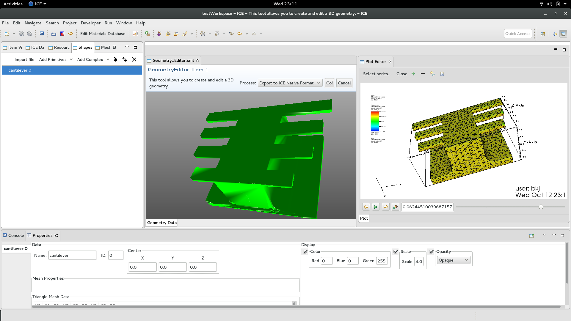 Figure 1
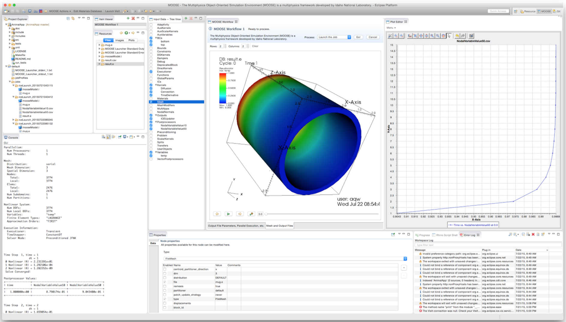 Figure 2
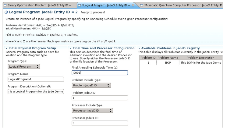 Figure 3
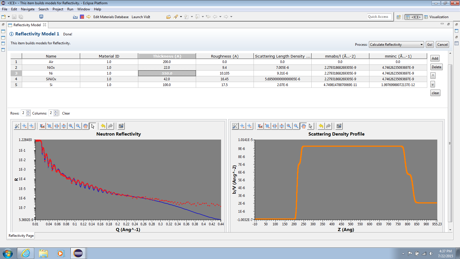 Figure 4
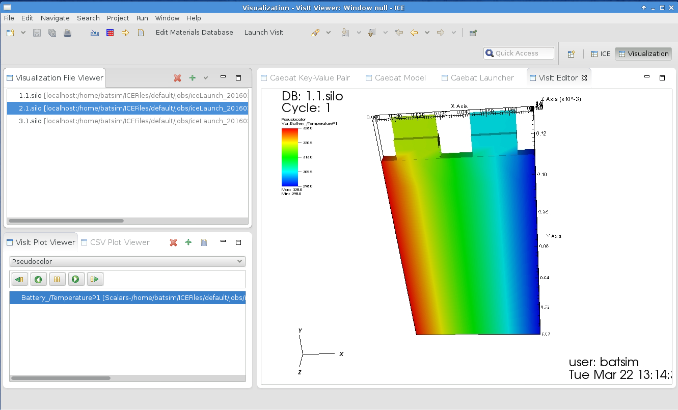 Figure 5
| Class | Class Description | Object Description |
|---|---|---|
| Item | Java class with code to execute an abstract workflow. Provides a Form. | Concrete workflow executor. |
| Form | Description and template of the data needed for the Item to process the workflow. | User-modified workflow data. |
| Action | Java class for executing a specific task in the workflow. Used by Items. | Concrete workflow task executor. |
| C1 | Current code version | ‘next’ |
|---|---|---|
| C2 | Permanent link to code/repository used for this code version | https://github.com/eclipse/ice/tree/next |
| C3 | Legal code license | Eclipse public license 1.0 |
| C4 | Code versioning system used | Git |
| C5 | Software code languages, tools, and services used | Java, OSGi, Eclipse RCP, and Maven |
| C6 | Compilation requirements, operating environments and dependencies | Java 1.8 or greater, Maven, and an internet connection for dependencies |
| C7 | If available, link to developer documentation/manual | https://wiki.eclipse.org/ICE |
| C8 | Support email for questions | [email protected] |
| S1 | Current code version | 2.2.1 |
|---|---|---|
| S2 | Permanent link to executables of this version | https://www.eclipse.org/downloads/download.php?file=/ice/builds/2.2.1/ |
| S3 | Legal software license | Eclipse public license 1.0 |
| S4 | Computing platforms/operating systems | Windows (32/64-bit), Mac OS/X, Linux (32/64-bit) |
| S5 | Installation requirements and dependencies | Java 1.8 or greater |
| S6 | If available, link to user manual. If formally published, include a reference to the publication in the reference list | https://wiki.eclipse.org/ICE |
| S7 | Support email for questions | [email protected] |
Peer Reviews
No public reviews on file for this paper yet. If you reviewed it on a platform where reviews are public (OpenReview, ICLR, NeurIPS, ICML), you can paste yours below so the community can read it here.
Code & Models
Videos
No videos yet. Explain this paper in a talk, walkthrough, or lecture? Add one.
The Eclipse Integrated Computational Environment
Jay Jay Billings1,2
[email protected], Twitter: @jayjaybillings
Andrew R. Bennett1,3
Jordan Deyton1,4
Kasper Gammeltoft1,5
Jonah Graham6
Dasha Gorin1,7
Hari Krishnan8
Menghan Li9
Alexander J. McCaskey1
Taylor Patterson1,10
Robert Smith1
Gregory R. Watson1
Anna Wojtowicz1,11
1Computer Science and Mathematics Division, Oak Ridge National Laboratory, Oak Ridge, TN 37830, USA
2The Bredesen Center for Interdisciplinary Research and Graduate Education, University of Tennessee, 444 Greve Hall, 821 Volunteer Blvd. Knoxville, TN 37996-3394
3University of Washington, Seattle, WA 98105
4General Electric Company, 3200 North Grandview Blvd Waukesha, WI 53188-1678
5Georgia Institute of Technology North Avenue, Atlanta, GA 30332
6Kichwa Coders Ltd. 1 Plomer Green Avenue Downley, High Wycombe HP13 5LN United Kingdom
7Northwestern University 633 Clark Street Evanston, IL 60208
8Lawrence Berkeley National Laboratory, 1 Cyclotron Rd, Berkeley, CA 94720
9Department of Computer Science, and Department of Biological Sciences, Purdue University, West Lafayette, IN 47906
10Acato Information Management, LLC 114 Union Valley Rd. Oak Ridge, TN 37830
11Colorado State University Fort Collins, CO 80523
Abstract
Problems in modeling and simulation require significantly different workflow management technologies than standard grid-based workflow management systems. Computational scientists typically interact with simulation software in a feedback-driven way where solutions and workflows are developed iteratively and simultaneously. This work describes common activities in workflows and how combinations of these activities form unique workflows. It presents the Eclipse Integrated Computational Environment as a workflow management system and development environment for the modeling and simulation community. Examples of the Environment’s applicability to problems in energy science, general multiphysics simulations, quantum computing, and other areas are presented along with its impact on the community at large.
keywords:
workflows , workflow management , supercomputing , usability , eclipse
PACS:
07.05.Tp
1 Notice of Copyright
This manuscript has been authored by UT-Battelle, LLC under Contract No. DEAC05-00OR22725 with the U.S. Department of Energy. The United States Government retains and the publisher, by accepting the article for publication, acknowledges that the United States Government retains a nonexclusive, paid-up, irrevocable, world-wide license to publish or reproduce the published form of this manuscript, or allow others to do so, for United States Government purposes. The Department of Energy will provide public access to these results of federally sponsored research in accordance with the DOE Public Access Plan (http://energy.gov/downloads/doe-public-access-plan ).
2 Motivation and Significance
In previous work, Billings et al. interviewed modeling and simulation subject matter experts to compile a list of requirements for implementing and using these kinds of applications. In the process, they discovered that many of the difficulties inherent in using high-performance modeling and simulation software fall into five distinct categories [1]. These activities, detailed in Section 2.0.1, include (1) creating input, (2) executing jobs, (3) analyzing results, (4) managing data, and (5) modifying code. There are many tools that address these problems individually, but the same research found that the excess number and specialization of these tools also contribute to the learning curve.
Previous efforts to address these five issues have resulted in general purpose scientific workflow tools like Kepler [2] or myopic tools that only satisfy a single set of requirements for a single piece of software or a single platform. These are opposite extremes, but a middle-of-the-road solution is also possible. A workflow engine could be developed that limits its scope to high-performance computing (HPC) and to the set of possible workflows associated with the five previously mentioned activities. With only minor additional development, a rich application programming interface (API) could be exposed so that highly customized solutions could still be made based on this limited workflow engine.
It is not clear which, if any, of these solutions is better than the others, and practical requirements will ultimately dictate the path of a project’s progress. This work considers a middle ground solution and presents the Eclipse Integrated Computational Environment (ICE) as proof that it is possible to create such a system. Specifically, the work described here shows that:
- •
Modeling and simulation activities can be described in a succinct workflow model (see “Workflow Model”).
- •
An architecture for such a workflow system can satisfy the model of workflows in an extensible way (see “Software Architecture”).
- •
Such a system is applicable to a suite of problems in energy science, including virtual battery simulations and additive manufacturing, among others (see “Illustrative Examples”).
This section concludes with an introduction of the ICE workflow model. Section 3 details the software from an architectural perspective, while Section 4 provides a set of comprehensive examples. A presentation of the impact is included in Section 5, and sample code is provided in Section 6.
2.0.1 Workflow Model
Computational scientists perform a variety of tasks in modeling and simulation that can be abstracted into a lightweight theoretical framework based broadly on five high-level activities: (1) creating input, (2) executing jobs, (3) analyzing results, (4) managing data, and (5) modifying code. Those same computational scientists would most likely find these activities difficult for all codes with which they lack experience, whereas with their own codes—or those with which they are most familiar—these tasks may be so simple that they are taken for granted. Any particular combination of these activities across one or more scientific software package or code results in a unique workflow. Such a workflow is normally, but not always, requested by a human user and orchestrated by a workflow management system.
The most obvious workflow for any individual simulation code or collection of codes is to string the activities together, where the user’s workflow is to create the input, launch the job, perform some analysis, and manage the data—possibly modifying the code in the process. However, there are many other combinations, including re-running jobs with conditions or modifications or analyzing someone else’s data.111The authors have identified many unique combinations that define workflow “classes.” When possible, every effort is made to give the classes colloquial names such as “The Re-Run” or “The Graduate Student.”
Creating input is the process of describing the physical model or state of a system that will be simulated. This could include creating an input file(s) or making calls to an external process to configure a running program. In most situations, a computational scientist will modify existing input or create new input from a template. “Input” generally includes runtime parameters for the simulation framework (e.g., tolerances); configuration options (e.g., data locations, output locations, module configurations); properties of the materials to be simulated; and a discretization of the simulation space (e.g., mesh, grid, particle distribution). The collection of all required input can be quite large and may go by many names, including “input set,” “input package,” “problem,” or, simply, “input.” Often, the set of input files will be described in a “main” input file that acts as a kind of manifest to describe—and provide links to—all necessary information for a given problem.
In this work, it should be assumed—unless otherwise noted—that “input” refers to the entire set of input, not to a single file.
Executing jobs, or “running the workflow” in this context, is the process of performing calculations using a simulation code or framework based on known variables—the input. Models and simulation codes are typically run locally for small jobs or for development. Large simulations, on the other hand, typically require a large amount of hardware resources; these resources are usually off site (i.e., physically unavailable to the user) and are accessed remotely through Secure Shell (SSH) connections or similar protocols. Remote execution requires moving the input in advance of the execution and copying or moving the output to the user’s machine. In many cases, though, the output is too large to move to the user’s local machine.
Local and remote jobs are often monitored to ascertain a job’s status. This monitoring may be a simple check as to whether or not the execution has completed, or it may involve monitoring the output of individual quantities to examine the calculation state. The latter is often used to detect calculation errors that will result in incorrect results. If such problems are found, the job is typically cancelled (“killed”) to save compute resources and is then re-run later.
In this work, it should be assumed—unless otherwise noted—that “executing a job” includes monitoring that job in one or more ways, possibly including real-time updates to visualizations.
Analyzing results includes executing special jobs to transform data in one or more prescribed ways and producing artifacts with scientific significance from the transformed data. This may include, for example, post-processing results and visualizing the new data with dedicated visualization tools. For many types of scientific computing, this includes viewing the results of a simulation on a mesh or grid and extracting publication-quality images or movies from that data. Other cases may include analyzing results in preparation for follow-on simulations or performing feature extraction, classification, or activities for machine learning and data mining.
While this has many similarities to executing a job, it is distinctly different because the activity changes focus to satisfy the needs of a human operator. Simple data reduction, where the exact reduction is known, certainly qualifies as executing a job; however, analysis of model and simulation results is far from simple data reduction and is generally far more interactive for computational scientists.
Managing data includes moving, copying, storing, sharing, or otherwise interacting with data for or from simulations. This activity is the most pervasive because each of the other activities requires interacting with data in some way. In many cases, though, data is still managed for its own purposes, without performing a simulation, generating new input, or analyzing results. Examples include archiving data, packaging data for publications, and updating values manually (often in light of new information from publications).
Modifying code is not typically considered a part of a scientific computing workflow. However, modeling and simulation use cases often require users to explicitly modify code before execution, such as with the computational fluid dynamics code Nek5000, [3], or to issue special re-build instructions. Many computational scientists consider “their workflow” to be re-running software after modifications for purely exploratory purposes. This may be required if the model that the author is manipulating cannot be configured directly as part of the input but can be easily manipulated by hand.
2.0.2 Comparison to Other
Models
This model of workflows differs significantly from those of similar efforts in workflow science because it defines workflows in terms of activities. Other workflow models in the literature define a workflow as a collection of computing processes. For example, Yu and Buyya define grid workflows as “a collection of tasks that are processed on distributed resources in a well-defined order to accomplish a specific goal,” [4]. Others, such as Pizzi et al., subscribe to similar definitions [5]. This “process” view is acceptable where the workflow is static and does not require additional human input or “human in the loop” behavior after all the initial human input is provided. That is, a “process-oriented” definition is acceptable where all human input is provided in advance. However, workflows within ICE are fully interactive with regular call-backs to humans. It is simpler to discuss “activities” than it is to create a distinction between “human processes” and “computer processes.” Focusing on “activities” over processes (human or computer) also has the benefit of removing concrete elements such as hardware properties or software details that distract from details of workflows and workflow management systems. That is, considerations such as memory usage and raw performance are important, but questions about the abstract workflow or what the workflow management system should do are far more important.
3 Software Description
ICE was specifically created to address the workflow model described above, which is to say that it was created specifically to address hands-on workflows for computational scientists. Users download and execute ICE locally and it orchestrates workflows locally or remotely as required. It provides a comprehensive workbench for modeling and simulation that includes tools for workflows, visualization, data management, and software development.
3.1 Software Architecture
Workflows and tasks in ICE are not explicitly treated as trees, or directed acyclic graphs (DAGS), as is common with grid workflow tools [4]. Instead, ICE’s design is inspired by representational state transfer (REST) [6].
Users initiate requests to create, edit, update, or delete workflows from the “ICE Client” (the workbench). The list of available workflows that can be created is provided dynamically to the ICE Client by the “ICE Core,” which acts as a server. This information is provided dynamically because the information often changes at run time based on both the configuration of available workflow components in the registry and on persisted workflows that users have saved in their workspace. Information about workflows is provided to the Client by the Core through stateless “Forms” that describe the workflow and provide all the necessary information to understand what should process the workflow (but not how it should be processed). Once users modify the description of the workflow in the Form to provide their specific details, the Client dispatches a request to the Core to modify or process the workflow. The Core then uses the information from the Form to perform a service lookup for what should process the workflow.
Workflows in ICE are encoded in and processed by “Items” and each workflow type is a subclass of Item. Items are registered dynamically through a service registry in ICE (see Section 3.1.3) and provide the Forms for the ICE Core and Client. Since ICE’s design is highly object oriented, it is easiest to think of the Item class as a description of an abstract workflow and an Item object (an instance of the class) as a concrete workflow with all required execution details provided by its Form.
Individual components of workflows (i.e., workflow “tasks” or “nodes”) are either encoded directly in the workflow’s subclass of Item or provided as “Actions” that are dynamically registered with an “Action Factory” and obtained at runtime. Table 1 describes the differences between Items, Actions, and Forms.222An upcoming update to the API will include the formal introduction of IWorkflow, IWorkflowTask, and IWorkflowEngine interfaces to bring ICE’s API language closer to other systems. This must be done carefully to preserve backwards compatibility with the present API.
In addition to running as a desktop workbench, ICE can be run as a headless web server with a remote service interface and a web API. The web API is also used as the primary means of providing real-time feedback and monitoring support in ICE.
3.1.1 Item States
All Items in ICE are finite state machines where the states represent the abstract state of the workflow. For example, when an Item is first created, it enters the “Form Ready” state to indicate that it could, in theory, be processed after a user reviews it. After that review, it enters the “Ready to Process” state before it is processed and the “Processed” state after it is processed. There are several additional states for errors.
This design is very important. First, it means that all workflows in ICE, regardless of their actual details and functions, can only behave in a specific set of known and predictable ways, and this predictability simplifies the way the Core manages and interacts with Items. Second, by formalizing state and error checks, ICE explicitly delineates which workflows can be executed from those that must receive additional configuration. Finally, it allows developers implementing Items and Actions to specify, by contract, what is required before proceeding to the next task, processing the workflow, or declaring a successful execution.
3.1.2 Persistence and
Workspaces
When workflows are created and modified, ICE saves permanent copies of Forms to disk in a special directory called a “workspace.” Workspaces can contain projects, folders, and files; including data, code, input, and output. ICE automatically manages local and remote (or even local to remote) transfers of data files when executing workflows if the files are detected in the same directory of the workspace as the workflow itself. For example, when executing a remote job, ICE will automatically move the input file if it is specified in the workflow and available in the project directory of the workspace. Likewise, if the output is small enough, ICE will automatically move it back to local directory. By convention, all paths in ICE’s Forms are relative to the workspace root path. Workspace directories are specified by the user.
ICE handles persistence using a “persistence provider.” The default persistence provider uses JAX-RS to write Forms to XML [7]. In principle, other persistence providers could replace the XML-based provider since it is registered as a dynamic service, and a JAX-P based provider has been used in the past.
3.1.3 Extending the Framework to Add Custom
Workflows
ICE is an Eclipse Rich Client Platform (RCP) application [8], and has a plugin architecture based on Equinox, which is the reference implementation of the Open Service Gateway Initiative (OSGi) framework specification [9]. ICE uses over 1,200 additional packages from the Eclipse ecosystem to provide services like language support and visualization. Each unique element of ICE described in this work—including the Client, Core, Items, and data structures—are provided as plugins to Equinox. Most plugins are managed dynamically and provided as services that can be obtained through a service registry. Most file I/O in ICE, with only a few exceptions, interacts with the RCP’s resources plugin. This also includes remote resources that are managed with the Eclipse Parallel Tools Platform [10].
It is not possible to create new Items in ICE graphically, and—unless they provide their own plugin to the framework—users can only use the workflow Items provided by their version of ICE. This can seem like an onerous task to the novice user, especially if they do not know Java, but this design was chosen because it is, in the opinion of the authors, a far more sophisticated and sustainable way to create workflows than, for example, using a wiring diagram.
ICE provides built-in development tools to automatically generate “stubs” of plugins that can then be installed into the framework. This “self-hosting” makes it possible for new users to create complex, sophisticated workflows very quickly because they are not required to know how to interact with the framework. Furthermore, ICE provides a rich API, documentation, tutorials, and tools to further simplify the process.
There are many situations where configuring workflows graphically is unacceptable, such as when a very large number of workflows will be executed or the type of information required is very fine-grained. In these cases, it is often necessary to provide scripts to the workflow management system. ICE includes the Eclipse Advanced Scripting Environment (EASE) [11] for scripting because it provides a way to script Eclipse RCP projects natively in Javascript, Jython, and Python. This also makes it possible to extend the environment by adding Items in these languages.
3.2 Software Functionalities
The most important function of ICE is to serve as an easily extended workflow management system for computational scientists in support of the activities described above. In practice, it is most often used as a combination of workflow management system and development environment since it contains a significant amount of Eclipse’s software development tooling in addition to the workflow tools. The project has many users, but it is most heavily used by the development team to support workflow science and software development for energy science projects. The development team regularly uses the platform to quickly deploy new domain-specific workbenches in a matter of hours for small collections of workflows that are easy to encode.
Outside of the development team, ICE is commonly deployed as a sophisticated user environment for computational science projects (see Section 5) and as a visualization tool. The ICE source code originally contained a significant amount of visualization support, but at the request of users in the community that support was “spun off” in early 2016 as the Eclipse Advanced Visualization Project (EAVP) [12].
4 Illustrative Examples
The role that ICE plays as a workflow tool is best illustrated by the various ways in which it has been deployed, as shown in the following examples.
4.1 Virtual Battery
Simulations
Pannala et al. developed a Virtual Integrated Battery Environment (VIBE) as part of their research into safety and performance characteristics of lithium ion batteries [13]. VIBE includes ICE as part of its distribution, and new workflows were added to ICE to enable users to add multiple types of input, configure the simulation software, and launch simulations of virtual batteries. Interactive 3-D visualizations of the results were embedded in the launcher so that users can quickly find their results. Figure 1 shows a (simulated) prismatic-cell battery’s temperature distribution during discharge.
VIBE 1.0 is available as a virtual machine (for convenient deployment) in which the simulation software and ICE are provided side by side. The VIBE team’s more recent efforts for VIBE 1.1 include providing the simulation software in Docker containers so that users can download the latest, native version of ICE for their machine while simultaneously benefiting from a smaller virtual machine for the simulator.
4.2 Multiphysics Simulations with
MOOSE
The MOOSE Framework is a powerful, easy-to-use multiphysics framework developed at Idaho National Laboratory [14]. ICE provides workflow tools for MOOSE as well as specialized class generation utilities for developing custom MOOSE kernels. Many of the MOOSE tools in ICE were developed closely with the MOOSE team to reproduce various aspects of MOOSE’s user interface, known as “Peacock.” Figure 2 shows an example of the ICE workbench for a simple structural mechanics problem solved using the MOOSE framework [15].
There are over three hundred MOOSE-based applications, and it is very easy to create new MOOSE applications. The ICE development team uses ICE and MOOSE to quickly solve energy science problems with HPC resources and to deploy domain-specific workbenches. ICE provides features for automatic installation, configuration and optimization of scientific development environments. In the context of MOOSE, ICE includes support for automatically downloading and building MOOSE from MOOSE’s GitHub repository. This integration enables users to immediately begin developing complex multiphysics applications using the pre-installed Eclipse C Development Tools. Once the new MOOSE-based application is built, it will automatically work with the MOOSE workflow tools in ICE, although developers can also create customized workflow tools as needed.
4.3 Binder Jet Modeling
Solid-state sintering of parts printed using binder jetting significantly increases part strength by decreasing the part porosity and eliminating voids. However, this process does cause the resulting product to shrink and warp from its original layout. An ideal, near-net-shape, process combines binder jetting with solid-state sintering and accounts for warpage and deformation in the part’s design phase. Figure 3 shows an ICE-based workbench for performing simulations of this process with visualizations of the pre- and post-simulation properties of a central body with eight cantilevers. The primary deformation in this type of geometry is bending or drooping of the cantilevers, and ICE currently calls a custom MOOSE-based application (which was written in ICE as described above) for simulating the deformation of the cantilevers. The full application for this work is expected to be released near the end of 2017.
4.4 Neutron Reflectivity
ICE also includes a small utility for simulating neutron reflectivity and comparing the results to other data [16]. This utility was developed in collaboration with a team at ORNL’s Spallation Neutron Source to replace an older utility that was originally written in Visual Basic and distributed via Excel macros. The new utility, developed in ICE and shown in Figure 4, is capable of processing a single workflow.
4.5 Quantum Computing
As quantum computing grows, the need for sophisticated software that can utilize quantum hardware or perform calculations on simulated quantum hardware becomes more pressing. Humble et al. created a simulator for adiabatic quantum computers where workflows were added to ICE to support interaction with the simulator and to process large sets of quadratic binary optimization problems [17]. Figure 5 shows the workbench for this project.
ICE also supports other quantum computing projects, including the eXtreme-scale ACCelerator (XACC) effort [18]. XACC is a programming framework for extreme-scale, post-exascale accelerator architectures that can be integrated alongside existing, conventional applications.
4.6 Nuclear Energy
There are many examples of ICE’s role in modeling and simulation projects for nuclear energy, but for an example of the level of customization that is possible in ICE, readers are referred to the work outlined in [19]. Support for the “Reactor Analyzer” was dropped in ICE 2.1.8, but it demonstrated ICE’s ability to integrate many different nuclear energy tools for complex analysis.
5 Impact
The impact of software tools like ICE is difficult to quantify. However, there are several examples of when ICE has significantly assisted its development team and others.
One pressing area of interest and impact is that of interoperability between workflow systems. There have been significant prior efforts in combining large workflow management systems (e.g., Mandal et al. [20]), but the end goal of gaining the greatest advantage by using the best capabilities from multiple systems remains elusive. ICE’s unique perspective on workflows and its well-defined API make it possible to integrate multiple systems in a straightforward way. This allows it to connect to other workflow environments, such as Triquetrum, quite easily [21]. Triquetrum, like Kepler in [20], is a Ptolemy-based workflow engine [22]. Several of the authors of this paper are using it to investigate these issues.
It is widely known that tools that enable researchers to be more productive tend to improve the pursuit of existing research. The high extensibility of ICE and the tools that it combines from the larger Eclipse ecosystem have made it possible for researchers on the development team to quickly deploy new simulation environments for their research problems (e.g., the binder jet modeler and reflectivity tools mentioned earlier). Other tools created with ICE may not invent something radically new, but they tend to streamline interactions with those tools. Many ICE users, and certainly the development team, have experienced improvements in their software development efforts because of the tools that ICE provides or have learned new technologies because access to new tooling was as simple as installing more plugins through the Eclipse Marketplace.
The ICE development team does not track ICE’s user base, as useful as that would be, because of the extra work involved. However, various sources such as the VIBE mailing list, ICE’s own mailing lists, and website download statistics suggest that ICE has been used by over 350 people at one time or another and currently has about twenty “superusers,” including the development team.
A new cloud-based development tool based on ICE is under development by RNET Technologies, Inc. out of Dayton, Ohio in response to a Small Business Innovation Research award from the US Department of Energy. This web-based version of ICE will continue ICE’s support for nuclear energy and will integrate with cloud computing solutions like Amazon Web Services and ORNL’s Compute and Data Environment for Science (CADES). Additionally, while ICE has not directly led to any “spin-off” companies, ICE source code has been used in two spin-off projects: (1) EAVP (mentioned earlier) for advanced visualizations and (2) the Eclipse January project for scientific data structures [23]. ICE was also one of the founding projects of the Eclipse Science Working Group.
Eclipse ICE is an open-source project, and the authors welcome and encourage engagement and contributions from users. Interested parties may inquire by contacting the corresponding author or visiting the ICE website.
6 Sample Code, Tutorials, and Other
Resources
The primary resource for information on ICE is the project’s website [24]. The “Resources” menu includes links to detailed tutorials and user documentation. Examples of how to create new workflow Items are available at https://github.com/eclipse/ice/tree/master/org.eclipse.ice.demo. Examples of how to use the scripting engine are available at https://github.com/eclipse/ice/tree/master/examples. ICE also includes an extensive suite of unit, integration, and UI tests, which are also excellent examples of how to work with the platform. Tutorial and demonstration videos are available on YouTube at https://goo.gl/nxCzRD.
7 Conclusions
Modeling and simulation workflows for computational scientists differ greatly from those of experimentalists or those who primarily interact with grid-based workflow management systems. The Eclipse ICE effort described here has been used to address interdisciplinary problems in modeling and simulation for energy science. Of particular interest are the differences in architecture between a workflow management system focused on modeling and simulation compared to those focused on grids. ICE’s broad applicability across many topics in energy science suggests that there are opportunities for these systems in general. Finally, one interesting avenue of future exploration is coupling or integrating ICE with other workflow tools such as Aiida, Triquetrum, Kepler, and Pegasus, which would make it possible to combine the best of grid and modeling workflows and simulation workflows to address greater challenges.
Acknowledgments
The authors are grateful for the assistance and support of the following people and institutions without whom this work would not have been possible. This includes many people who directly contributed to the project, either in its early days as “NiCE” or once it moved to Eclipse, including: Ronald Allen, Andrew Belt, Tim Bohn, David E. Bernholdt, Erica Grant, Mike Guidry, Forest Hull, Eric J. Lingerfelt, Sebastien Jourdain, JiSoo Kim, Allison Koenecke, Fangzhou Lin, Greg Lyon, Tony McCrary, John M. Hetrick III, Elizabeth Piersall, Neeti Pokhriyal, Adrian Sanchez, Claire Saunders, Nick Stanish, Matthew Wang, and Scott Wittenberg. The support of both the Nucleare Energy Advanced Modeling and Simulation (NEAMS) and Consortium for Simulation of Light-water Reactors (CASL) programs is also greatly appreciated. The authors would like to acknowledge the special contribution of the Eclipse Foundation, the Eclipse Community, the Eclipse Science Working Group, and our many colleagues who use and contribute to open-source projects in the Eclipse ecosystem.
Finally, the development team is especially grateful to Barney Maccabe, David Pointer, and John Turner of ORNL for their endless support and advocacy for this work.
This work has been supported by the US Department of Energy, Offices of Nuclear Energy (DOE-NE) and Energy Efficiency and Renewable Energy (DOE-EERE), and by the ORNL Undergraduate Research Participation Program, which is sponsored by ORNL and administered jointly by ORNL and the Oak Ridge Institute for Science and Education (ORISE). This work was also supported in part by the ORNL Director’s Research and Development Fund. ORNL is managed by UT-Battelle, LLC, for the US Department of Energy under contract no. DE-AC05-00OR22725. ORISE is managed by Oak Ridge Associated Universities for the US Department of Energy under contract no. DE-AC05-00OR22750.
Required Metadata
Current Code Version
See Table 2.
Current Executable Software
Version
See Table 3.
The reference list from the paper itself. Each links out to its DOI / PubMed record.
- 1[1] Jay J. Billings, Wael R. Elwasif, Lee M. Hively, David E. Bernholdt, John M. Hetrick, III, and Tim Bohn. Designing a Component-based Architecture for the Modeling and Simulation of Nuclear Fuels and Reactors. In Proceedings of the 2009 Workshop on Component-Based High Performance Computing , CBHPC ’09, pages 6:1–6:4, New York, NY, USA, 2009. ACM.
- 2[2] Bertram Ludäscher, Ilkay Altintas, Chad Berkley, Dan Higgins, Efrat Jaeger, Matthew Jones, Edward A. Lee, Jing Tao, and Yang Zhao. Scientific workflow management and the Kepler system. Concurrency Computat.: Pract. Exper. , 18(10):1039–1065, August 2006.
- 3[3] The Nek 5000 Team. Nek 5000 | A Spectral Element code for CFD, October 2014.
- 4[4] Jia Yu and Rajkumar Buyya. A Taxonomy of Workflow Management Systems for Grid Computing. J Grid Computing , 3(3-4):171–200, September 2005.
- 5[5] Giovanni Pizzi, Andrea Cepellotti, Riccardo Sabatini, Nicola Marzari, and Boris Kozinsky. Aii DA: automated interactive infrastructure and database for computational science. Computational Materials Science , 111:218–230, January 2016.
- 6[6] Roy Thomas Fielding. Architectural Styles and the Design of Network-based Software Architectures . Ph D thesis, University of California, Irvine, 2000. AAI 9980887.
- 7[7] Bill Burke. RES Tful Java with JAX-RS . O-Reilly, California, 2010.
- 8[8] Jeff Mc Affer, Jean-Michel Lemieux, and Chris Aniszczyk. Eclipse Rich Client Platform Second Edition . Addison-Wesley, Boston, 2010.