Advanced Quantizer Designs for FDD-Based FD-MIMO Systems Using Uniform Planar Arrays
Jiho Song, Junil Choi, Taeyoung Kim, and David J. Love

TL;DR
This paper proposes advanced quantizer designs for FDD-based FD-MIMO systems with uniform planar arrays, improving channel state information quantization accuracy and efficiency for massive MIMO deployments.
Contribution
It introduces novel narrowband and wideband CSI quantizers tailored for UPA-based FD-MIMO, incorporating realistic channel properties and hierarchical beam search methods.
Findings
Proposed quantizers outperform previous techniques in simulations.
Hierarchical beam search reduces computational complexity.
Enhanced channel quantization accuracy improves MIMO system performance.
Abstract
Massive multiple-input multiple-output (MIMO) systems, which utilize a large number of antennas at the base station, are expected to enhance network throughput by enabling improved multiuser MIMO techniques. To deploy many antennas in reasonable form factors, base stations are expected to employ antenna arrays in both horizontal and vertical dimensions, which is known as full-dimension (FD) MIMO. The most popular two-dimensional array is the uniform planar array (UPA), where antennas are placed in a grid pattern. To exploit the full benefit of massive MIMO in frequency division duplexing (FDD), the downlink channel state information (CSI) should be estimated, quantized, and fed back from the receiver to the transmitter. However, it is difficult to accurately quantize the channel in a computationally efficient manner due to the high dimensionality of the massive MIMO channel. In this…
Click any figure to enlarge with its caption.
 Figure 1
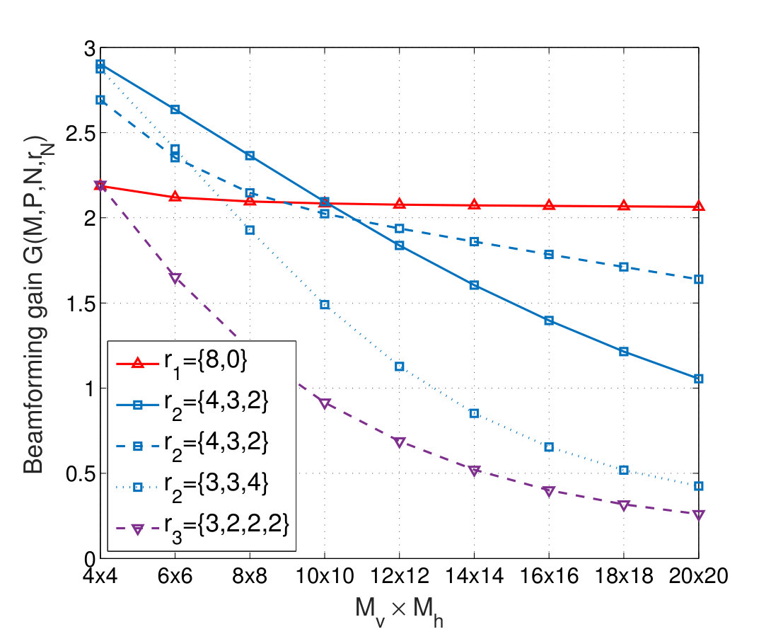 Figure 2
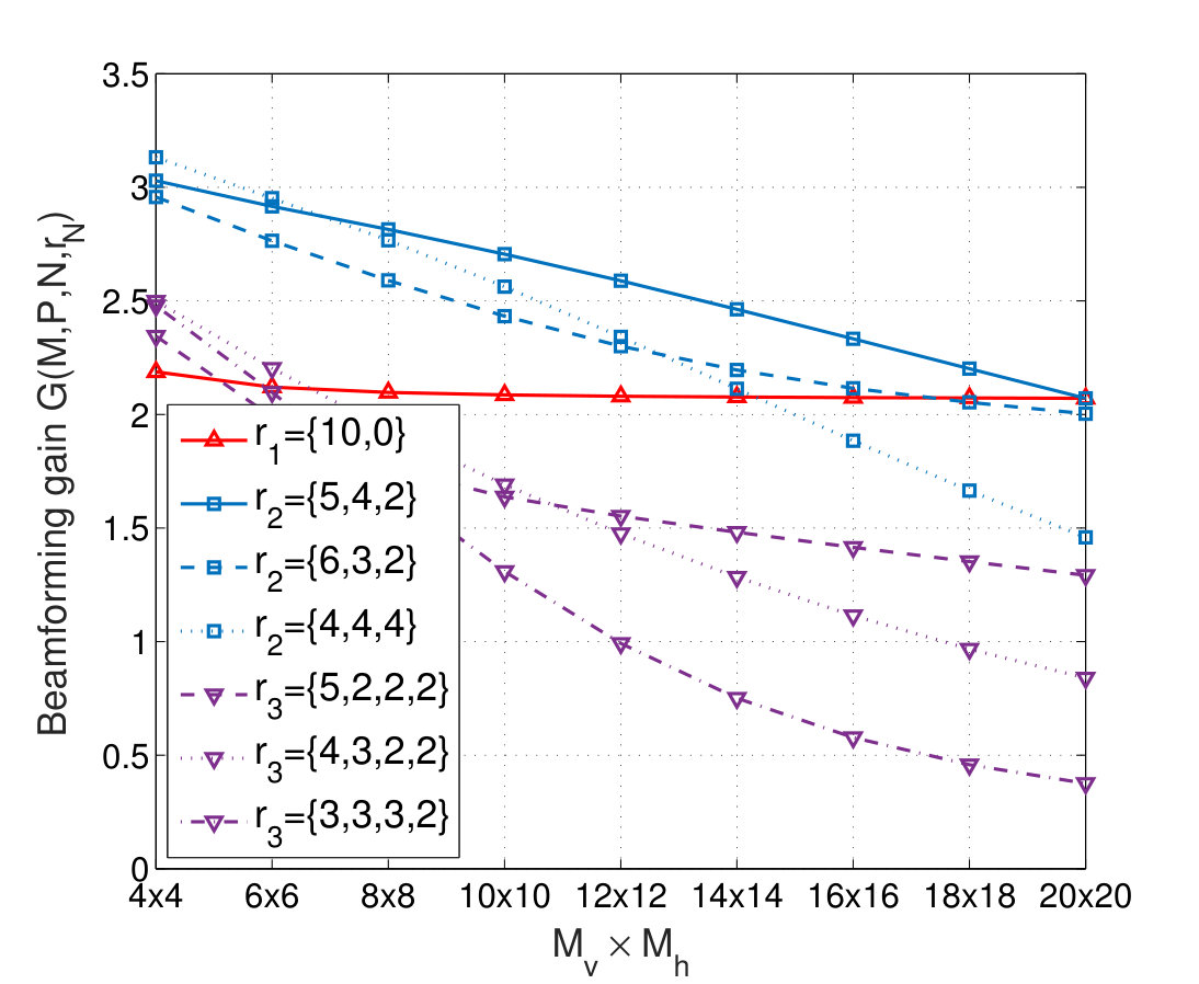 Figure 3
 Figure 4
 Figure 5
 Figure 6
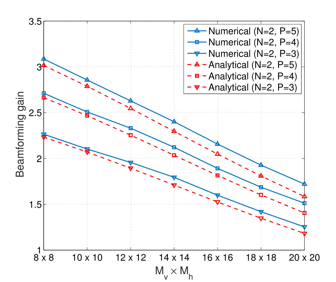 Figure 7
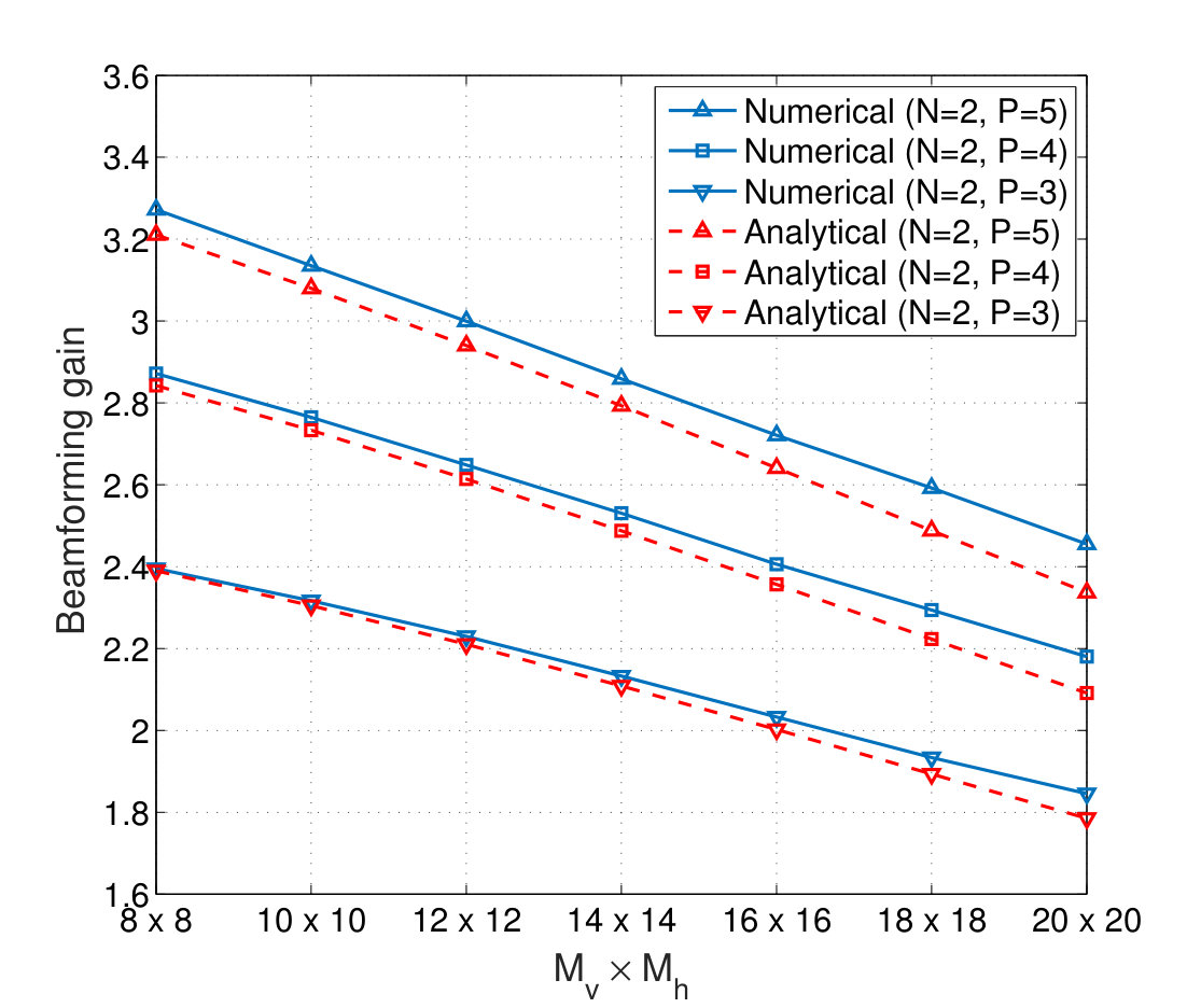 Figure 8
 Figure 9
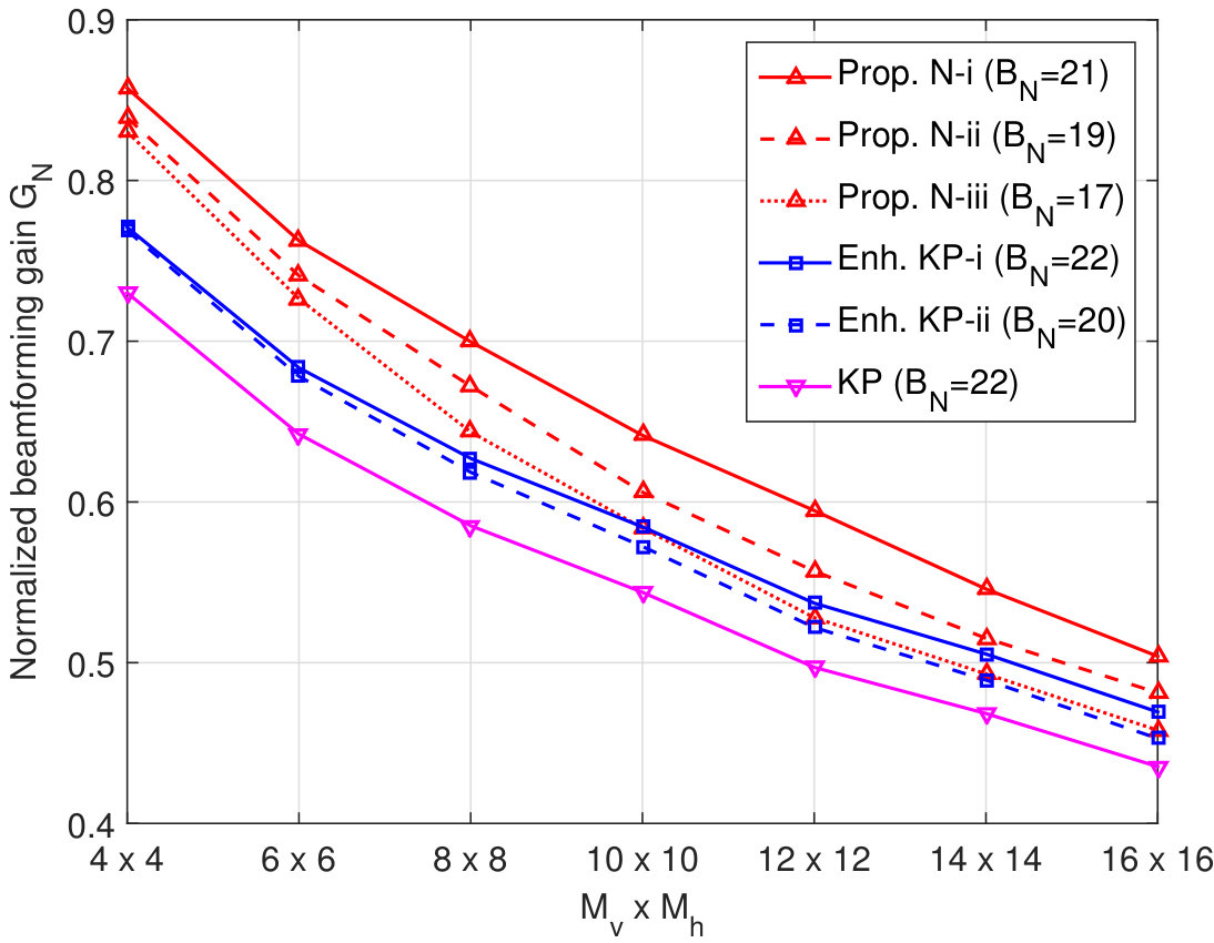 Figure 10
 Figure 11
 Figure 12
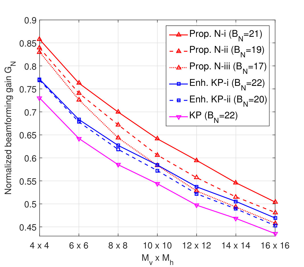 Figure 13
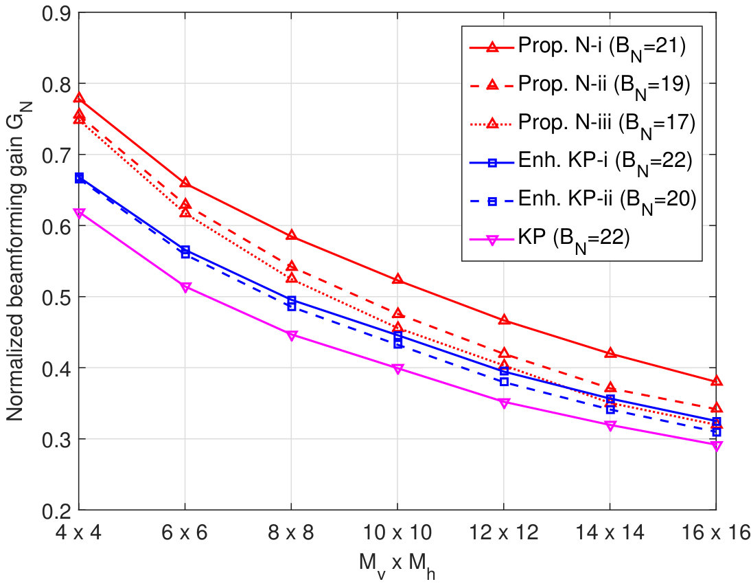 Figure 14
 Figure 15
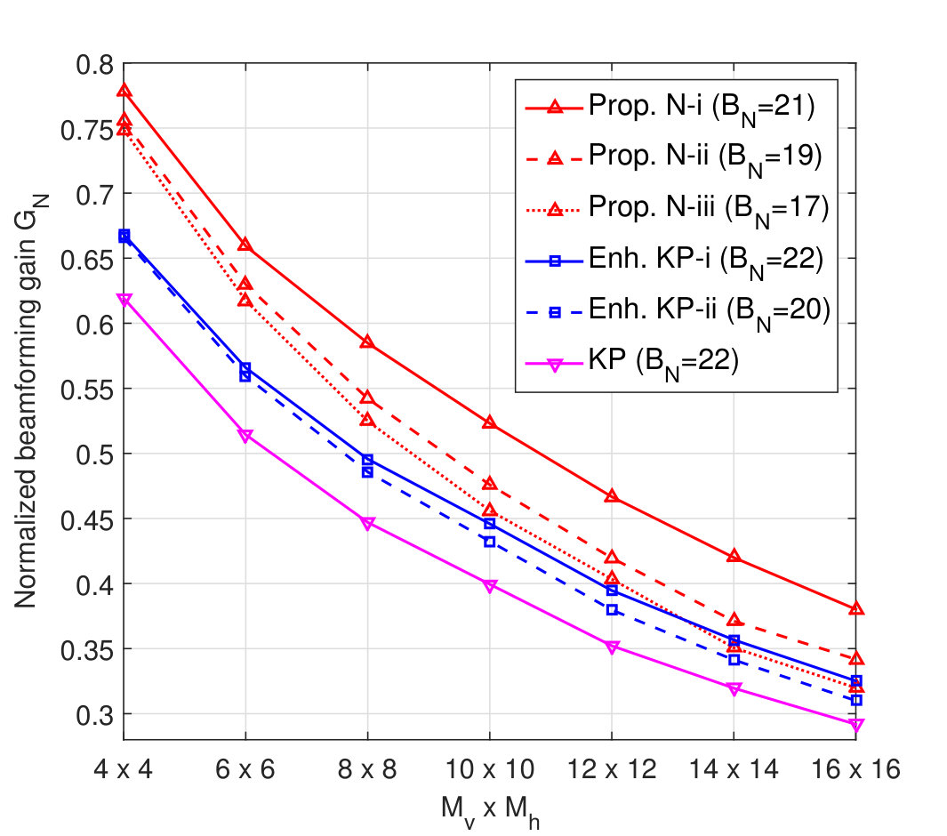 Figure 16
 Figure 17
 Figure 18
 Figure 19
 Figure 20
 Figure 21
 Figure 22
 Figure 23
 Figure 24
 Figure 25
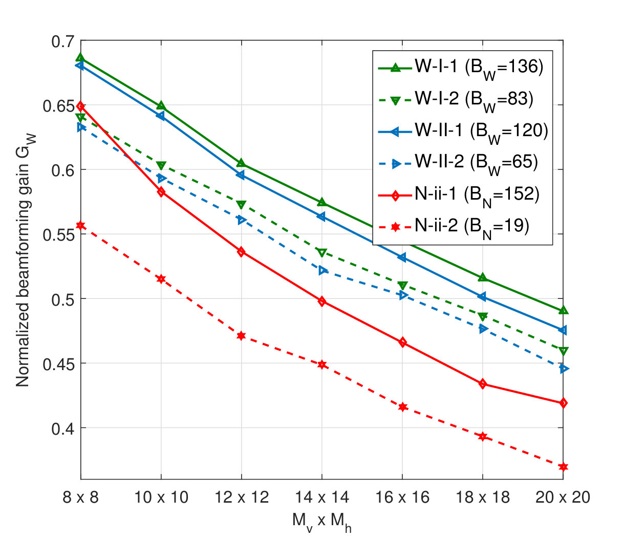 Figure 26
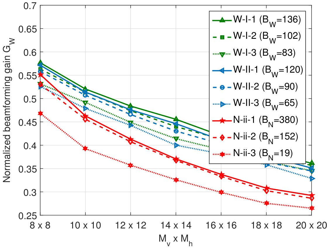 Figure 27
 Figure 28
 Figure 29
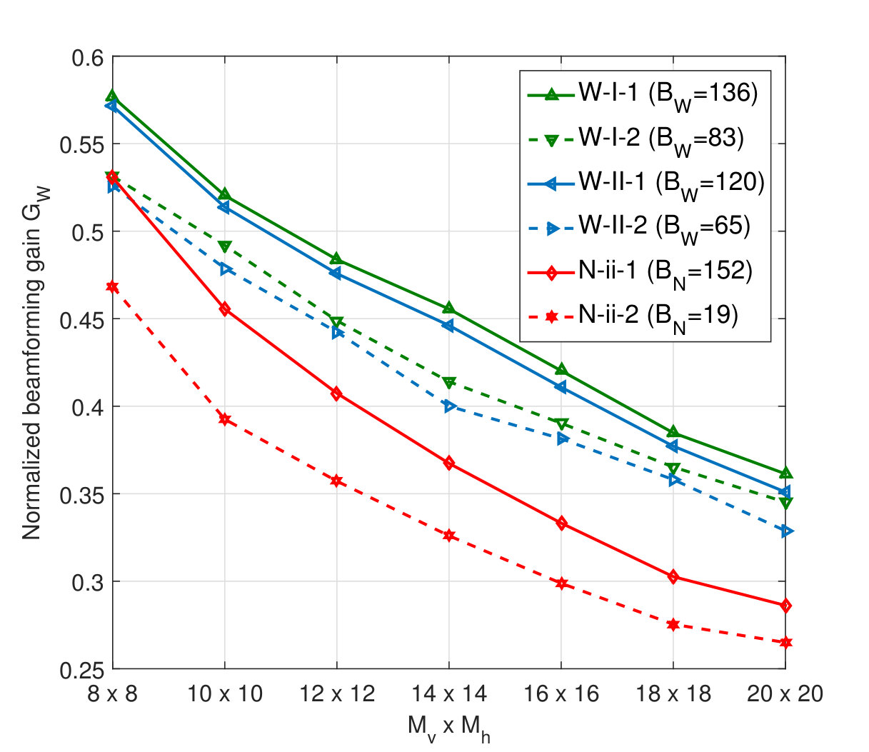 Figure 30
| Tx antennas | to Co-polarized UPA |
|---|---|
| Rx antennas | Co-polarized UPA |
| Scenario | UMi NLOS |
| Carrier frequency | GHz |
| Subcarrier spacing | KHz |
| Vertical antenna spacing | |
| Horizontal antenna spacing |
| round | round | |||
|---|---|---|---|---|
| Prop. N-i | 3,072 | |||
| Prop. N-ii | 1,536 | |||
| Prop. N-iii | 768 | |||
| Enh. KP-i | 2,176 | |||
| Enh. KP-ii | 1,120 | |||
| KP codebook | 4,096 |
| Feedback overhead | Vector computations | |
|---|---|---|
| Prop. quantizer | ||
| Enhanced KP | ||
| KP codebook |
| Level : Wideband RB | Level : Narrowband RB | |
|---|---|---|
| W-I | ||
| W-II |
| Narrowband quantizer | Wideband quantizer | ||
|---|---|---|---|
| N-1 | 1 codeword / 75 tones | W-1 | |
| N-2 | 1 codeword / 600 tones | W-2 |
Peer Reviews
No public reviews on file for this paper yet. If you reviewed it on a platform where reviews are public (OpenReview, ICLR, NeurIPS, ICML), you can paste yours below so the community can read it here.
Videos
No videos yet. Explain this paper in a talk, walkthrough, or lecture? Add one.
Advanced Quantizer Designs for FDD-Based FD-MIMO Systems Using Uniform Planar Arrays
Jiho Song, Junil Choi, Taeyoung Kim, and David J. Love J. Song is with School of Electrical Engineering, University of Ulsan, Ulsan, 44610, Korea (e-mail:[email protected]).J. Choi is with the Department of Electrical Engineering, POSTECH, Pohang, Gyeongbuk 37673, Korea (e-mail:[email protected]).T. Kim, is with Samsung Electronics Co., Ltd., Suwon, Korea (email:[email protected]).D. J. Love is with the School of Electrical and Computer Engineering, Purdue University, West Lafayette, IN 47907 (e-mail:[email protected]).Parts of this paper were presented at the Globecom, Washington, DC USA, December 4-8, 2016 [1].This work was supported in part by Communications Research Team (CRT), Samsung Electronics Co. Ltd., and the ICT RD program of MSIP/IITP [2017(B0717-17-0002), Development of Integer-Forcing MIMO Transceivers for 5G Beyond Mobile Communication Systems].
Abstract
Massive multiple-input multiple-output (MIMO) systems, which utilize a large number of antennas at the base station, are expected to enhance network throughput by enabling improved multiuser MIMO techniques. To deploy many antennas in reasonable form factors, base stations are expected to employ antenna arrays in both horizontal and vertical dimensions, which is known as full-dimension (FD) MIMO. The most popular two-dimensional array is the uniform planar array (UPA), where antennas are placed in a grid pattern. To exploit the full benefit of massive MIMO in frequency division duplexing (FDD), the downlink channel state information (CSI) should be estimated, quantized, and fed back from the receiver to the transmitter. However, it is difficult to accurately quantize the channel in a computationally efficient manner due to the high dimensionality of the massive MIMO channel. In this paper, we develop both narrowband and wideband CSI quantizers for FD-MIMO taking the properties of realistic channels and the UPA into consideration. To improve quantization quality, we focus on not only quantizing dominant radio paths in the channel, but also combining the quantized beams. We also develop a hierarchical beam search approach, which scans both vertical and horizontal domains jointly with moderate computational complexity. Numerical simulations verify that the performance of the proposed quantizers is better than that of previous CSI quantization techniques.
Index Terms:
Massive MIMO, full-dimension MIMO, uniform planar arrays, Kronecker product codebooks.
I Introduction
Massive multiple-input multiple-output (MIMO) systems are a strong candidate to fulfill the throughput requirements for fifth generation (5G) cellular networks [2]. To maximize the number of antennas in a limited area, two-dimensional antenna arrays, e.g., uniform planar arrays (UPAs) and cylindrical arrays, that host antennas in both vertical and horizontal domains are being prominently considered in practice [3, 4]. Among various 2D array solutions, UPAs are of great interest to simplify signal processing for three-dimensional (3D) channels for FD-MIMO. Massive MIMO employing a UPA structure is known as full-dimension (FD) MIMO because of its ability to exploit both vertical and horizontal domain beamforming [5, 6, 7, 8, 9, 10].
To fully exploit FD-MIMO, accurate channel state information (CSI) for both domains is critical. Channel estimation techniques relying upon time division duplexing (TDD) can leverage channel reciprocity if the transmit and receive arrays are calibrated [11, 12]. Moreover, it has been recently verified that the spectral efficiency of TDD-based massive MIMO increases without bound as the number of antennas grows, even under pilot contamination [13]. Most current cellular systems, however, exploit frequency division duplexing (FDD) where the receiver should estimate, quantize, and feed back the downlink CSI to the transmitter. The high dimensionality of a massive MIMO channel could cause large overheads for downlink channel training and quantization processes [14, 15, 16, 17, 18, 19, 20]. We focus on CSI quantization for FD-MIMO in this paper and refer to [19, 20, 21] and the references therein for the massive MIMO downlink training problem.
The majority of CSI quantization codebooks have been designed under the assumption of spatially uncorrelated Rayleigh fading channels, which are uniformly distributed on the unit hypersphere when normalized. To quantize these channels, the codewords in a codebook should cover the unit sphere as uniformly as possible [22, 23, 24]. For spatially correlated channels, the codebooks have been carefully shaped based on the prior knowledge of channel statistics [25, 26, 27, 28, 29].
Although most previous codebooks have been designed based on analytical channel models, it is difficult to represent the properties of true three-dimensional (3D) channels for FD-MIMO. The 3D spatial channel model (SCM) in [4, 30], which is an extension of the 2D SCM [31], has been extensively used to mimic the measured channel variations for 3GPP standardization. Although the 3D SCM is a stochastic channel model, it provides limited insights into practical CSI quantizer designs. Therefore, it is necessary to develop a simple channel model that accurately represents the properties of the 3D-SCM channel with UPA antennas.
In this paper, we define a simple 3D channel model using the sum of a finite number of scaled array response vectors. Based on this simplified channel model, we develop CSI quantizers for UPA scenarios. We first carry out performance analysis of Kronecker product (KP) CSI quantizers [1, 9]. Our analytical studies on the KP CSI quantizers provide design guidelines on how to develop a quantizer for a narrowband, single frequency tone CSI using limited feedback resources. In the proposed quantizer, we concentrate on detecting/quantizing dominant radio paths in true channels. To maximize quantization quality, we also develop a codebook for combiners that cophases and scales the quantized beams. Both vertical and horizontal domains are searched during beam quantization, which involves a heavy computational complexity. We thus develop a hierarchical beam search approach to reduce the complexity.
We also develop a wideband quantizer for broadband communication by evolving the dual codebook structure in LTE-Advanced [32, 33]. In the dual codebook structure, a first layer quantizer is used to search correlated CSI between multiple frequency tones. Unless dominant paths are gathered in a single cluster, the LTE-Advanced codebook is not effective because only adjacent radio paths are selected and quantized using the same resolution codebook. We thus concentrate on detecting adjacent and/or sperate paths within each wideband resource block (RB) based on the proposed hierarchical beam search approach. In addition, a second layer quantizer is designed to refine the beam direction of the quantized wideband CSI according to the channel vectors in a narrowband RB. When comparing our approach to the LTE-Advanced codebook, the refined beams are cophased and scaled in our approach, while the LTE-Advanced codebook only cophase adjacent beams without considering beam refinement.
In Section II, we describe FD-MIMO systems employing UPAs and discuss a simple channel model that mimics true 3D SCM channels. In Section III, we review previously reported KP codebooks. In Section IV, we develop a narrowband CSI quantizer that takes multiple radio paths into account and conduct performance analysis to develop a design guideline for CSI quantizers. In Section V, we also propose a wideband CSI quantizer assuming a multi-carrier framework. In Section VI, we present simulation results, and the conclusion follows in Section VII.
Throughout this paper, denotes the field of complex numbers, denotes the semiring of natural numbers, denotes the complex normal distribution with mean and variance , is the closed interval between and , denotes the uniform distribution in the closed interval , is the ceiling function, denotes the complete gamma function, is the expectation of independent random variable , is the -norm, is the Hadamard product, is the Kronecker product, is the all zeros vector, is the identity matrix, is the all ones matrix, , , and denote entry, the -th dominant eigenvector, and the -th dominant eigenvalue of the matrix . Also, , , , denote the conjugate transpose, element-wise complex conjugate, -th entry, and subvector including entries between of the column vector , respectively.
II System Model
We consider multiple-input single-output (MISO) systems111Although we mainly discuss MISO channel quantization to simplify presentation, the proposed channel quantizer can be easily extended to multiple-input multiple-output (MIMO) systems. The extension of the MISO channel quantizer will be discussed in Section IV-C. employing transmit antennas at the base station and a single receive antenna at the user, where is the number of rows and is the number of columns of the UPA antenna structure [3]. Assuming a multi-carrier framework, an input-output expression is defined as
[TABLE]
where is the received baseband symbol, is the signal-to-noise ratio (SNR), is the block fading MISO channel, is the unit-norm transmit beamformer, is the data symbol with the power constraint , and is the additive white Gaussian noise. Note that denotes the frequency tone in the multi-carrier framework.
To facilitate quantizer designs, we mimic the 3D-SCM and define a simplified channel model with a few radio paths according to
[TABLE]
while the true 3D-SCM is used to present numerical results in Section VI. In (2), is the number of dominant paths, is the subcarrier spacing, is the excess tap delay of the -th radio path, is the channel gain of the -th radio path, and is the -th radio path at given angles . In the UPA scenario, a radio path for the -th frequency tone is represented as
[TABLE]
where the array response vector is defined as
[TABLE]
for . In (4), and [34]. Note that is the antennas spacing, is the angle for the array vector, and is the wavelength for the -th frequency tone CSI
[TABLE]
where is the center frequency satisfying with the speed of light . Without loss of generality, a narrowband representation of channels is defined by plugging222We consider the -th subcarrier to ignore beam squinting effects [35]. into (2)
[TABLE]
where {\mathbf{D}}\doteq\big{[}{\mathbf{d}}_{M}(\psi_{1}^{v},\psi_{1}^{h}),\cdots,{\mathbf{d}}_{M}(\psi_{p}^{v},\psi_{p}^{h})\big{]}\in\mathbb{C}^{M\times P} is the set of radio paths and is the set of complex channel gains. In the narrowband assumption, is dropped for simplicity. We assume that the beam directions are uniformly distributed in both vertical and horizontal domains such as and are independent of channel gains .
In the limited feedback beamforming approach, each user chooses a transmit beamformer among codewords in the codebook such that
[TABLE]
where denotes the total feedback overhead. Based on the assumption that both transmitter and receiver know the predefined codebook, the -bit index of the selected beamformer is fed back to the transmitter over the feedback link.
The majority of channel quantization codebooks have been designed for spatially correlated and uncorrelated Rayleigh fading channels [22, 23, 24, 25, 26, 27, 28, 29]. These analytical channel models rely upon rich scattering environments so that each radio path has a limited effect on channel characterization. Thus, most previous beamformer codebooks focus on covering the unit hypersphere as uniformly as possible without considering each radio path individually. However, the analytical channel models are much different than realistic channel models that assume only a few dominant scatterers. Therefore, this line-packing codebook design approach may not be effective when the number of antennas is large. To accurately quantize high-dimensional massive MIMO channels, it is important to tailor the codebook to the realistic channels consisting of a limited number of radio paths.
III Kronecker Product Codebook Review - Single Beam Case
It is critical in FDD massive MIMO systems to quantize and feedback information about the high-dimensional channels to the transmitter [14, 15, 16, 17, 18, 19, 20]. Thus, CSI quantization codebooks have been developed to tailor the feedback link with limited overhead to the massive MIMO channels [16, 17, 18]. Among various CSI quantization techniques,333In massive FD-MIMO systems, formulating a low-dimensional feature abstraction problem for quantizing true channel vectors would be an interesting topic for future research. KP codebooks are of great interest to quantize the channels in a computationally efficient manner by considering the 2D antenna structure [9, 10]. Based on the channel model in (6), KP codebooks are designed to quantize a radio path with UPA structure [6, 7, 8].
Most KP codebooks are based on the assumption that the covariance matrix of the channels is approximated by the KP of covariance matrices of vertical and horizontal domains such that [36]
[TABLE]
Thus, a KP codebook is of the form
[TABLE]
to quantizes a single dominant path with the discrete Fourier transform (DFT) codebook
[TABLE]
consisting of the codewords
[TABLE]
Most previous KP codebooks quantize the first dominant vector in each domain separately [6, 7, 8, 9]. To find singular vectors, the channel vector in (6) is decomposed into both vertical and horizontal domains based on the singular value decomposition [9] yielding
[TABLE]
where the reshaped channel is given in a matrix form
[TABLE]
In (8), denotes the -th dominant singular value, denotes the -th dominant left singular vector, and denotes the -th dominant right singular vector of . The final codeword is then obtained as , where
[TABLE]
Despite the advantage of a KP codebook, it has some issues. Even with a line-of-sight (LOS) channel, a dominant radio path may not be accurately quantized by searching each domain separately. Also, it is not always effective to quantize only a single radio path because even may consist of multiple paths. Although the quantizer in [9] considers adding two beams in , the performance improvement is limited because the beams are not combined properly.
IV Proposed Narrowband Quantizer - Multiple Beams Case
Prior work has verified that most 3D SCM channel realizations are well modeled with only a few resolvable 2D radio paths [1, 9]. Thus, we assume that the channel vector on a single frequency tone can be represented by a combination of a set of multiple radio paths and its corresponding channel gain vector [1]. In (6), the array response vectors in and the channel gain vector contain different types of channel information. Thus, we focus on quantizing and using different codebooks in this paper.
In our narrowband quantizer, we aim to find
[TABLE]
by constructing a set of beams and a unit-norm weight vector . The radio paths constituting the channels are represented by the Kronecker product of array response vectors as in (3). Thus, each 2D beam in can be defined by a combination of quantized array response vectors in vertical and horizontal domains such that
[TABLE]
We assume that -bit is reserved to quantize the -th array response vector in the domain and -bit is reserved to quantize the weight vector .
To construct and under the condition of a limited feedback overhead of -bits, the following questions should be properly addressed.
1) Beam quantization: How should the radio paths in the channel be chosen and quantized?
2) Beam combining: How should the quantized beams be cophased and scaled?
3) Feedback resource allocation: For a given total feedback overhead , how should the feedback-bit allocation scenario
[TABLE]
be defined to effectively quantize and combine the limited number of radio paths?
In the following subsections, we address our channel quantization procedure across two separate quantization phases and evaluate quantization loss at each phase.
Remark 1
The quantized channel vector can be viewed as a representation of the channel using an analog beamsteering matrix , which is realized by a set of radio frequency phase shifters, and a baseband beamformer . Therefore, the proposed approach follows the hybrid beamforming architecture in [37].
IV-A Phase I: Beam Quantization
In the beam quantization phase, we aim to construct a selected set of quantized 2D beams . It is well known that the DFT codebook is an effective solution to quantize array response vectors so that we quantize the -th array response vector with the DFT codebook .
In our beam quantization approach, we select and quantize the 2D DFT beams sequentially. In the -th update, the quantized DFT vectors and the unquantized weight vector444The bar on the top of weight vectors denotes the unquantized weight vectors. are obtained by solving the maximization problem555Assuming a multiuser framework, the interuser interference can be suppressed by maximizing the beamforming gain, i.e., minimizing the quantization error.
[TABLE]
where , and includes previously selected DFT beams.
In (11), we do not quantize the weight vector in each update because it is not practical to construct a codebook for weight vectors that constantly change its dimension. The problem of choosing the -th DFT beam is then simplified to
[TABLE]
where is derived from the unquantized weight vector, which is computed based on the generalized Rayleigh quotient [38], such that
[TABLE]
The beam quantization approach gives a set of quantized beams
[TABLE]
and the unquantized weight vector
[TABLE]
A separate beam quantization should be performed to compute each codeword candidate based on Algorithm 1. In the following Section IV-E, a practical beam search technique will be proposed to quantize a single dominant beam with moderate computational complexity as well as compute multiple codeword candidates in a hierarchical fashion.
We also evaluate quantization loss due to the beam quantization as a function of the number of beams and the feedback overhead for DFT codebooks. Assuming the unquantized weight vector , the beamforming gain between the channel vector and the set of DFT beams
[TABLE]
is averaged over channel realizations in Lemma 1. Before presenting the lemma, we make the following assumption.
Assumption 1
Assuming a channel vector has already been decomposed into a set of radio paths and channel gains as in (6), the column vectors for each domain in are separately selected as , where
[TABLE]
Considering half-wavelength antenna spacing , the beamforming gain between the -th array response vector and the selected DFT vector \Gamma_{na}^{2}\doteq\mathrm{E}{\big{[}|{\mathbf{d}}_{M_{a}}^{H}(\psi_{n}^{a}){\mathbf{c}}_{n}^{a}|^{2}\big{]}} is derived in Appendix A as
[TABLE]
Lemma 1
A lower bound of the beamforming gain in (15) is approximated as
[TABLE]
Please check Appendix B for the proof.
IV-B Phase II: Beam Combining
In the beam combining phase, we aim to compute a weight vector , which is used to combine beams in . To quantize weight vector
[TABLE]
we design the codebook including unit-norm combiners . To study a codebook design framework, we model the effective channel vector based on the Kronecker correlation model as
[TABLE]
where the covariance matrix {\mathbf{R}}\doteq\mathrm{E}_{{\mathbf{h}}}\big{[}{\mathbf{C}}^{H}{{\mathbf{h}}}{{\mathbf{h}}}^{H}{\mathbf{C}}\big{]}\in\mathbb{C}^{N\times N} in (22) is analytically computed in Appendix C and random variables denotes the weight vector that is subject to the equal gain subset
[TABLE]
In our codebook design approach, we pick a set of codewords that maximize
[TABLE]
where the inequality in is based on and , and is approximated by plugging the Kronecker correlation model in (18) into the maximizer.
Based on the correlated Grassmannian beamforming algorithm in [25], codewords are then obtained by setting
[TABLE]
and picking a set of equal gain vectors maximizing
[TABLE]
where equal gain vectors are restricted to
[TABLE]
Note that denotes the phase quantization level.
We also evaluate the quantization loss due to the beam combining as a function of the number of codewords in the codebook that quantizes the baseband combiner in (14). To analyze quantization performance of , the normalized beamforming gain between the normalized effective channel and the selected unit-norm combiner
[TABLE]
is averaged over the effective channel . Because it is not easy to compute in a closed form, we only derive the normalized beamforming gain in the special case of based on the following assumption.
Assumption 2
For simple analysis, we assume that the combiner is selected as , where
[TABLE]
Note that .
Lemma 2
In the special case of , the normalized beamforming gain in (20) is approximated as
[TABLE]
Please check Appendix D for the proof.
IV-C MIMO Channel Quantizer
Before investigating feedback allocation solutions, we extend the proposed quantizer to MIMO channel scenarios. Assuming a MIMO system employing receive antennas at each user, the channel matrix is defined as
[TABLE]
In our MIMO channel quantization approach, DFT beams are chosen to solve the rewritten problem
[TABLE]
where the unit-norm combiner is defined by considering possible channel correlations at the receiver according to
[TABLE]
and the unquantized weight vector is computed such as
[TABLE]
After constructing the selected set of DFT beams , we next compute a set of orthogonal receive combiners and transmit beamformers for spatial multiplexing. For a given set of beams , we compute the beamformer for the -th layer transmission , where the unquantized weight vector
[TABLE]
is computed based on the generalized Rayleigh quotient [38]. The unit-norm receive combiner is then given by
[TABLE]
The combining and precoding matrix are then constructed as
[TABLE]
respectively, where denotes the maximum transmission rank.666Note that designing a beam combining codebook and a feedback resource allocation algorithm that support multi layer MIMO transmission are interesting topics for future research. Finally, the receive combining and precoding matrix are multiplied to the left and right side of the channel matrix such as
[TABLE]
IV-D Feedback Resource Allocation
In our KP codebook procedure, quantizing more beams with a high resolution codebook increases the beamforming gain at the cost of increased feedback overhead. To effectively allocate limited feedback overhead resources, we must derive the beamforming gain between the randomly generated channel vectors and the selected codeword using
[TABLE]
as a function of the feedback-bit allocation scenario777In , for denotes the size in bits of the DFT codebooks in the domain , and denotes the size in bits of the codebook for combiners . in (10). However, inter-dependencies across both quantization phases in Section IV-A and Section IV-B make it hard to compute the beamforming gain in a closed form. To simplify analysis, we make the following assumption.
Assumption 3
Assuming the quantization phases in Section IV-A and Section IV-B work independently, the channel quantization quality in the proposed KP codebook procedure is evaluated by the combination of the quantization losses in both phases.
Based on Assumption 3 that both quantization phases are independent of each other, the beamforming gain in the proposed quantizer is defined by the mixture of and such as,
[TABLE]
where is the number of antennas, is the number of beams in , is the number of dominant beams to be quantized, and is the feedback-bit allocation scenario in (10).
In the proposed quantizer, the feedback scenario are chosen as
[TABLE]
by evaluating all possible scenarios that considers beams in . Note that the possible feedback scenarios are subject to the total feedback overhead -bits. In (23), the expectation is taken over the number of dominant paths since varies depending on the channel environments. By assuming is equally probable from to , we plot the arithmetic mean of in Fig. 1 with different numbers of antennas and feedback bits.
As shown in the figure, quantizing one or two beams give the best performance under practical UPA scenarios and feedback overheads. Therefore, we construct the codebook for quantizing a single 2D DFT beam and the codebook combining two quantized 2D DFT beams based on the predefined feedback-bit allocation scenarios888The total feedback overhead for feedback scenarios are -bits and -bits, where .
[TABLE]
respectively. The final codebook is then defined such that
[TABLE]
Remark 2
In most of channel realizations, the inter-user interference due to the remained paths is negligible because most of channel gains are contained in the first and second dominant beams [1, 9]. Based on the codebook subset restriction algorithm in [39, 40], severe inter-user interference could be mitigated by reporting the remained paths having a considerable amount of channel gains.
IV-E Beam Search Approach
It is necessary to search both vertical and horizontal domains jointly to scan for the dominant beams in a channel vector. However, this joint approach increases a computational complexity. For example, it is required to carry out vector computations to scan a single 2D DFT beam under the feedback-bit allocation scenario in (24). To reduce the heavy computational complexity that comes with detecting the single dominant beam, we propose a multi-round beam search technique as follows.
Round 1: For the channel vector , the first dominant beam is chosen using DFT codebooks and in (7), which have low-resolution DFT vectors. The DFT beam is given by
[TABLE]
Later, the selected 2D DFT beam in (25) will be a baseline that guides the generation of two codeword candidates.
Round 2: In this round, -bits are assigned for constructing the two codeword candidates.
- To support channel realizations having a single dominant beam, a codeword is computed based on the feedback-bit allocation scenario in (24) by scanning beam directions near from Round 1. The first codeword is given by
[TABLE]
where is defined to shift the beam directions999The Hadamard product formulation satisfies the following formulation and the -bit size codebook
[TABLE]
is designed for refining beam directions of any DFT beams.
In our CSI quantization approach, the first codebook is then defined such that
[TABLE]
over , , and .
- To support channel realizations having multiple dominant beams, a codeword is computed based on the feedback-bit allocation scenario in (24) by choosing an additional DFT beam to combine with . The second codeword is given by
[TABLE]
using -bits size DFT codebooks and and -bits size codebook , which is developed to combine the two 2D DFT beams as explained in the Section IV-B.
Considering our CSI quantization technique, the second codebook is then defined such that
[TABLE]
over , , , , and .
Round 3: Using the two codeword candidates and , the final codeword is selected with an additional bit
[TABLE]
V Proposed Wideband Quantizer
We develop a wideband quantizer that takes multiple frequency tones into account. Before developing practical quantizers, we overview a broadband system model adopted in 3GPP LTE-Advanced. As shown in Fig. 2(a), total frequency tones are divided into wideband RBs where each wideband RB includes channels. Each wideband RB is written in a matrix form as
[TABLE]
As depicted in Fig. 2(b), each wideband RB is divided into narrowband RBs
[TABLE]
where denotes the narrowband RB that is written in a matrix form.
Next, the correlation between the channel vectors is studied numerically based on the cross correlations over
[TABLE]
where denotes 3D-SCM channel vectors and denotes the dominant 2D DFT beam that is chosen from the DFT codebooks and in (7) for subcarrier . As shown in Fig. 3, it is verified that the dominant 2D DFT beams in the different subcarriers’ channel vectors are highly correlated. Based on empirical studies, the wideband quantizer is designed in such a way that the correlated information, i.e., the dominant 2D DFT beam, is shared between neighboring subcarriers.
Level 1 (Wideband resource block): We choose two 2D DFT beams that are close to the channel vectors in each wideband RB. For supporting the -th wideband RB, the first 2D DFT beam is chosen as
[TABLE]
with -bit DFT codebooks. Next, the second 2D DFT beam is chosen using -bit DFT codebooks as
[TABLE]
over .
Level 2 (Narrowband resource block): Within the -th wideband RB, the set of 2D DFT beams and will be a baseline that guide the quantization of channel vectors in each narrowband RB. To construct each set of two codeword candidates, -bits are allocated for each narrowband RB.
Round 1: The first codeword is computed to support the channel scenario having a single dominant beam. The first codeword quantizes channel vectors in the -th narrowband RB of the -th wideband RB by refining the beam direction of according to
[TABLE]
with -bit codebooks in (26).
Round 2: The second codeword is computed to support the channel scenario having two dominant beams. The proposed quantizer only refines the direction of as well as combines with the second 2D DFT beam . The second codeword is
[TABLE]
over in (26) and . Out of -bits allocated for each narrowband RB, bits are assigned for refining the first 2D DFT beam and bits are assigned for combining the two 2D DFT beams.
Round 3: Among the two codeword candidates, the final codeword is selected with an additional bit according to
[TABLE]
VI Simulation Results
We verify the performance of our CSI quantizers. Before evaluating the proposed quantizers, we pause to validate the accuracy of the approximated beamforming gain in (22). The beamforming gain between the simplified channel and the quantized channel is computed as in (21). For numerical simulations, channels in (6) are generated by assuming a fixed number of the ray-like beams . In Fig. 4, it is shown that the approximated formula in (22) gives a tight lower bound on the numerical results in (21).
We now evaluate the narrowband quantizers using simulations. Numerical results are obtained through Monte Carlo simulations with channel realizations. For generating 3D-SCM channels, we use the parameters in Table I. We evaluate the normalized beamforming gain of narrowband quantizer
[TABLE]
where is the final codeword101010The perfect CSI beamformer gives the normalized beamforming gain of one. that is chosen in (27). We compare the beamforming gains of the proposed quantizer with that of the KP codebooks in [6, 7] and the enhanced KP codebook in [9]. The feedback-bit allocation111111The feedback-bit allocation scenarios for the proposed narrowband quantizers are predefined in (24). of each quantizer is listed in Table II and the computational complexity121212We count the number of vector computations to evaluate the complexity. and feedback overhead131313The feedback overhead (per each frequency tone CSI) is assessed by the combination of the overheads for both the first and second rounds in Section IV-E. are summarized in Table III.
In Figs. 5(a) and 5(b), the normalized beamforming gains of the three quantizers are plotted with different antenna spacing scenarios. The proposed quantizer searches both vertical and horizontal domains jointly, while other KP codebooks search beams lying in each domain independently and integrate the results later. The 2D DFT beams, which are quantized in the proposed quantizer, are aligned by cophasing and scaling each beam. On the contrary, the quantized beams in the enhanced KP codebook [9] are simply added up together without considering phase alignment. For these reasons, the proposed quantizer generates higher beamforming gains than those of other KP codebooks.
We next evaluate the normalized beamforming gain of the wideband quantizer according to
[TABLE]
where is the chosen codeword in (30). In Figs. 6(a) and 6(b), the normalized beamforming gains of wideband quantizer are compared with those of the narrowband quantizers. In the legend, the first alphabet denotes the type of quantizer, the second alphabet denotes the feedback-bit allocation scenario in Table IV, and the final digit represents the wideband configuration141414In the LTE setup of scheme W-3, the first narrowband RBs have tone CSIs and the ninth narrowband RB has tone CSIs. in Table V. The total feedback overhead of the proposed wideband quantizer is defined as
[TABLE]
Numerical results verify that wideband quantizers outperforms narrowband quantizers because it exploits correlation between frequency tone CSIs. The wideband quantizers also reduce feedback overhead because they can maintain quantization performance with less overhead compared to narrowband quantizers.
VII Conclusion
In this paper, advanced CSI quantizers based on the KP codebook structure are proposed for FD-MIMO systems using UPAs. In the proposed quantizer designs, we focused on detecting and quantizing a limited number of dominant 2D beams in 3D channel vectors by exploiting DFT codebooks. The codebook for combiners was designed to cophase and scale the quantized 2D DFT beams. Furthermore, we analytically derived a design guideline for practical quantizers, which is based on FD-MIMO systems with predefined feedback-bit allocation scenarios.
We then developed CSI quantizers by taking the predefined feedback scenarios into account. First, a narrowband quantizer was proposed to quantize and/or combine one or two dominant 2D DFT beams. To detect and quantize beams properly, we also developed a multi-round beam search approach that scans both vertical and horizontal domains jointly under the moderate computational complexity. To reduce total feedback overhead, we also proposed a wideband quantizer that utilizes the correlated information between multiple frequency tones. Numerical simulations verified that the proposed narrowband quantizer gives better quantization performance than previous CSI quantization techniques, and the proposed wideband quantizer further improves the quantization performance with less feedback overhead compared to the narrowband quantizer in wideband settings.
Appendix A Correlation between array response vector and DFT codeword
We discuss the correlation between the array response vector in the domain and the selected DFT codeword to quantify the quantization performance of DFT codebooks by evaluating
[TABLE]
where is rewritten with the index of selected codeword
[TABLE]
The expectation over is rewritten by defining the new random variable as , which follows because . The correlation formula151515We assume that the number of oversampled DFT codewords is larger than the number of antennas, e.g., , in each domain . Assuming , the correlation formula is always positive, i.e., , because . is then computed over , as
[TABLE]
Appendix B Lower bound of normalized beamforming gain
Remark 3
To simplify analysis, we consider the first order Taylor expansion of the bivariate variables, which is derived as in [41],
[TABLE]
Expectation of the bivariate variables is then approximated as
[TABLE]
The beamforming gain in Lemma 1 is lower bounded as
[TABLE]
where the inequality in is based on and , holds when , and is derived based on Remark 3.
To complete the lower bound in (31), we first compute the expectation of two-norm squared of the effective channel vector
[TABLE]
where is derived by using the correlation between the channel vector and the -th selected DFT codeword \mathrm{E}\big{[}|{{{\mathbf{h}}}}^{H}({\mathbf{c}}_{n}^{v}\otimes{\mathbf{c}}_{n}^{h})|^{2}\big{]} that will be discussed in Appendix E.
We next consider the set of DFT vectors in (13). The expectation of two-norm squared of is approximated as
[TABLE]
subject to . Note that \mathrm{E}\big{[}{\mathbf{C}}^{H}{\mathbf{C}}\big{]} is computed as
[TABLE]
where with is chosen as in (16). Because we assume that beam directions are uniformly distributed , can be chosen as one of codewords in the DFT codebook with equal probabilities. For this reason, we can obtain \mathrm{E}\big{[}({\mathbf{c}}_{c}^{a})^{H}{\mathbf{c}}_{d}^{a}\big{]} in (41) by computing its arithmetic mean of the beamforming gain between two different codewords () as
[TABLE]
Based on \mathrm{E}\big{[}{\mathbf{C}}^{H}{\mathbf{C}}\big{]}, the expectation of two-norm squared of in (33) is approximated as
[TABLE]
where is derived because , which holds when .
Finally, the lower bound of in (31) is approximated by plugging the derived formulas in (32) and (43) into (31) as
[TABLE]
Appendix C Covariance matrix of effective channel vector
Each entry of in (22) is rewritten in (37). Note that \mathrm{E}\big{[}({\mathbf{c}}_{c}^{a})^{H}{\mathbf{d}}_{M_{a}}({\psi_{p}^{a}}){\mathbf{d}}_{M_{a}}^{H}({\psi_{p}^{a}}){\mathbf{c}}_{d}^{a}\big{]} in (37) is computed depending on the different cases as follows:
Case 1: .
[TABLE]
where is derived in Appendix A.
Case 2: .
[TABLE]
where is chosen as in (16). Note that is derived by computing the arithmetic mean.
Case 3: .
[TABLE]
where is derived because
[TABLE]
Note that is derived because with the definition of for any in (16).
Case 4: .
[TABLE]
where is derived by computing the arithmetic mean.
Appendix D Quantization performance of
The normalized beamforming gain between the effective channel vector and the selected combiner is lower bounded as
[TABLE]
In (38), is based on with , is approximated because and , and is approximated based on Remark 3 in Appendix B.
Although is simplified in (38), it is still difficult to solve in most cases. In the special case of , the equal gain vectors can be defined as
[TABLE]
using , and the beamforming gain in (38) is then derived such as
[TABLE]
Note that is derived based on the definition that follows because , , and based on Assumption 2. In addition, is derived by computing its arithmetic mean because is equally probable from to , and is derived because
[TABLE]
and the arithmetic mean of is derived as
[TABLE]
Appendix E Correlation between channel vector and DFT codeword
We derive a correlation between the channel in (6) and the -th selected 2D DFT beam
[TABLE]
where \Gamma_{na}^{2}\doteq\mathrm{E}{\big{[}\big{|}{\mathbf{d}}^{H}_{M_{a}}(\psi_{n}^{a}){\mathbf{c}}_{n}^{a}\big{|}^{2}\big{]}} is derived in Appendix A. Note that is derived because when and is derived because
[TABLE]
To complete the formula in (39), we compute the power of the -th largest channel gain . Without loss of generality, we assume that the magnitude of channel gains are in descending order, i.e., . The channel gain follows that is characterized by the cumulative distribution function (cdf) of
[TABLE]
because . We now consider the -th order statistic (-th smallest order statistic) of i.i.d exponentially distributed random variables . Then, we refer to [42] for defining the pdf of , yielding
[TABLE]
where is derived based on the binomial expansion formula. Then, the expectation of -th order statistic is defined as
[TABLE]
Notice that is derived because for any function , is derived because , is derived based on , and is derived based on . We now compute the -th largest channel gain as
[TABLE]
Finally, the correlation coefficient is rewritten by plugging into (39).
[TABLE]
The reference list from the paper itself. Each links out to its DOI / PubMed record.
- 1[1] J. Song, J. Choi, K. Lee, T. Kim, J. Y. Seol, and D. J. Love, “Advanced quantizer designs for FD-MIMO systems using uniform planar arrays,” in Proceedings of IEEE Global Telecommunications Conference , Dec. 2016.
- 2[2] T. L. Marzetta, “Noncooperative cellular wireless with unlimited numbers of base station antennas,” IEEE Transactions on Wireless Communications , vol. 9, no. 11, pp. 3590–3600, Nov. 2010.
- 3[3] R. C. Hansen, Phased array antennas , 2nd ed. Hoboken: Wiley-Interscience, 2009.
- 4[4] Y. H. Nam, B. L. Ng, K. Sayana, Y. Li, J. Zhang, Y. Kim, and J. Lee, “Full-dimension MIMO for next generation cellular technology,” IEEE Communications Magazine , vol. 51, no. 6, pp. 172–179, Jun. 2013.
- 5[5] R 1-150381, Discussions on FD-MIMO codebook enhancements , 3GPP TSG RAN WG 1 # # \# 80 Std., Feb. 2015.
- 6[6] R 1-150057, Codebook enhancements for EBF/FD-MIMO , 3GPP TSG RAN WG 1 # # \# 80 Std., Feb. 2015.
- 7[7] R 1-150560, Codebook for 2D antenna arrays , 3GPP TSG RAN WG 1 # # \# 80 Std., Feb. 2015.
- 8[8] J. Li, X. Su, J. Zeng, Y. Zhao, S. Yu, L. Xiao, and X. Xu, “Codebook design for uniform rectangular arrays of massive antennas,” in Proceedings of IEEE Vehicular Technology Conference , Jun. 2013.