Thrust vectoring of an electric solar wind sail with a realistic sail shape
Petri Toivanen, Pekka Janhunen

TL;DR
This paper models the shape of a rotating electric solar wind sail under realistic conditions, deriving equations for its shape and analyzing how it affects thrust vectoring and attitude control.
Contribution
It introduces a new analytical approximation for the sail shape considering centrifugal and solar wind forces, improving understanding of sail attitude maintenance.
Findings
The sail shape transitions from conical near the spacecraft to flattened at the rim.
The required voltage modulation for attitude control is smaller than previous rigid tether models.
Thrust vectoring can be effectively achieved with reduced thrusting margin.
Abstract
The shape of a rotating electric solar wind sail under the centrifugal force and solar wind dynamic pressure is modeled to address the sail attitude maintenance and thrust vectoring. The sail rig assumes centrifugally stretched main tethers that extend radially outward from the spacecraft in the sail spin plane. Furthermore, the tips of the main tethers host remote units that are connected by auxiliary tethers at the sail rim. Here, we derive the equation of main tether shape and present both a numerical solution and an analytical approximation for the shape as parametrized both by the ratio of the electric sail force to the centrifugal force and the sail orientation with respect to the solar wind direction. The resulting shape is such that near the spacecraft, the roots of the main tethers form a cone, whereas towards the rim, this coning is flattened by the centrifugal force, and the…
Click any figure to enlarge with its caption.
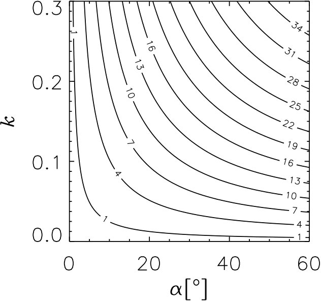 Figure 1
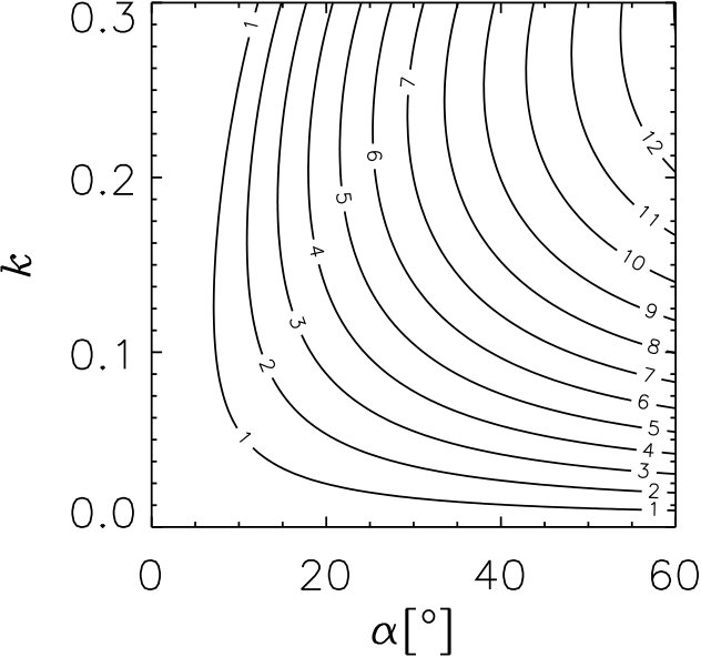 Figure 2
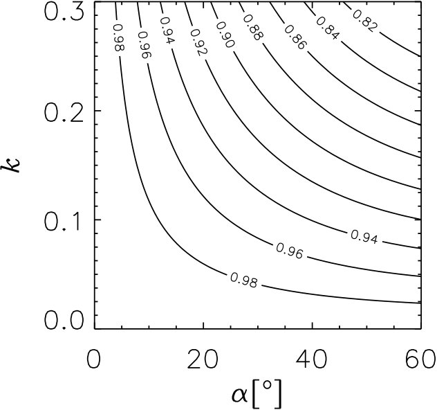 Figure 3
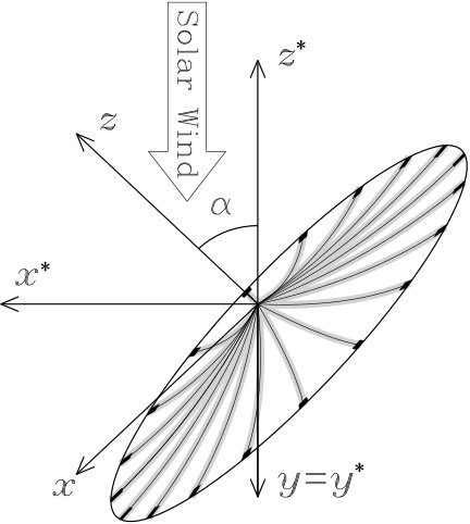 Figure 4
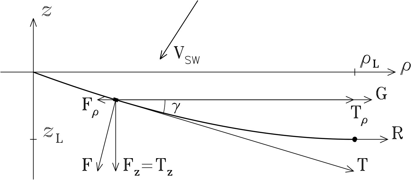 Figure 5
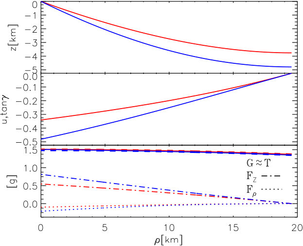 Figure 6
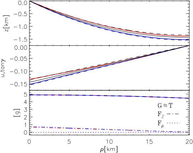 Figure 7
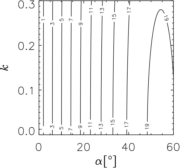 Figure 8
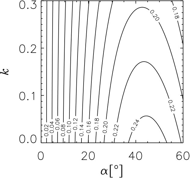 Figure 9
Peer Reviews
No public reviews on file for this paper yet. If you reviewed it on a platform where reviews are public (OpenReview, ICLR, NeurIPS, ICML), you can paste yours below so the community can read it here.
Videos
No videos yet. Explain this paper in a talk, walkthrough, or lecture? Add one.
Thrust vectoring of an electric solar wind sail with a
realistic sail shape
P. Toivanen and P. Janhunen
Finnish Meteorological Institute, FIN-00101, Helsinki, Finland
Abstract
The shape of a rotating electric solar wind sail under the centrifugal force and solar wind dynamic pressure is modeled to address the sail attitude maintenance and thrust vectoring. The sail rig assumes centrifugally stretched main tethers that extend radially outward from the spacecraft in the sail spin plane. Furthermore, the tips of the main tethers host remote units that are connected by auxiliary tethers at the sail rim. Here, we derive the equation of main tether shape and present both a numerical solution and an analytical approximation for the shape as parametrized both by the ratio of the electric sail force to the centrifugal force and the sail orientation with respect to the solar wind direction. The resulting shape is such that near the spacecraft, the roots of the main tethers form a cone, whereas towards the rim, this coning is flattened by the centrifugal force, and the sail is coplanar with the sail spin plane. Our approximation for the sail shape is parametrized only by the tether root coning angle and the main tether length. Using the approximate shape, we obtain the torque and thrust of the electric sail force applied to the sail. As a result, the amplitude of the tether voltage modulation required for the maintenance of the sail attitude is given as a torque-free solution. The amplitude is smaller than that previously obtained for a rigid single tether resembling a spherical pendulum. This implies that less thrusting margin is required for the maintenance of the sail attitude. For a given voltage modulation, the thrust vectoring is then considered in terms of the radial and transverse thrust components.
keywords:
Electric solar wind sail , Attitude control , Transverse thrust
††journal: Acta Astronautica††footnotetext: Telephone number: +358-50-5471521
Nomenclature
{xtabular}
@lcl@ a &= voltage modulation torque-free
c = cosine function
= unit vector
= electric sail force
= total sail thrust
= centrifugal force
= voltage modulation general
= integral
= force ratio
= main tether length
= coordinate along the main tether
= total mass
= number of main tethers
= single main tether mass
s = sine function
= main tether tension
= electric sail torque
= total sail torque
= local tether tangent
= solar wind velocity
= solar wind speed
= Cartesian coordinates
= sail angle
= local tether coning angle
= rotation period
= linear mass density
= thrust angle
= circular cylindrical coordinates
= angular torque density
= electric sail force factor
= sail spin rate
Subscripts
{xtabular}@lcl@ [math] &= tether root
= index
= tether length
= main tether
= vector component index
= remote unit
= sail
= Cartesian coordinates
= sail angle
= local tether coning angle
= circular cylindrical coordinates
Superscripts
{xtabular}@lcl@ &= summation index
= orbital frame of reference
1 Introduction
The electric solar wind sail is a propulsion system that uses the solar wind proton flow as a source of momentum for spacecraft thrust [1]. The momentum of the solar wind is transferred to the spacecraft by electrically charged light-weight tethers that deflect the proton flow. The sail electrostatic effective area is then much larger than the mechanical area of the tethers, and the system promises high specific acceleration up to about 10 mm/s2 [2]. As the tethers are polarized at a high positive voltage they attract electrons that in turn tend to neutralize the tether charge state. However, only a modest amount of electric power of a few hundred watts is required to operate electron guns to maintain the sail charge state, and the sail can easily be powered by solar panels [3, 4]. The main tethers are centrifugally deployed radially outward from the spacecraft in the sail spin plane (Fig. 1). To be tolerant to the micro-meteoroid flux each tether has a redundant structure that comprises a number (typically 4) of 20-50 m metal wires bonded to each other, for example by ultrasonic welding [5]. As a baseline design, the tips of the main tethers host remote units that are connected by auxiliary tethers at the sail perimeter to provide mechanical stability to the sail[6].
As the electric sail offers a large effective sail area with modest power consumption and low mass, it promises a propellantless continuous low thrust system for spacecraft propulsion for various kinds of missions [7]. These include fast transit to the heliopause [8], missions in non-Keplerian orbit such as helioseismology in a solar halo orbit [9], space weather monitoring with an extended warning time (closer to the sun than L1), multi-asteroid touring mission. Using the electric sail, such missions can typically be accomplished without planetary gravity assist maneuvers and associated launch windows. If planetary swing-bys are planned during the mission, each solar eclipse has to be carefully considered to avoid drastic thermal contraction and expansion of the sail tethers [10]. In addition to scientific missions, the electric sail can be used for planetary defense as a gravity tractor [11] or an impactor [12] and to rendezvous with such Potentially Hazardous Objects that cannot be reached by conventional propulsion systems [13]. The electric sail has also been suggested as a key method of transportation for products of asteroid mining[14]. Specifically, water from asteroids can be used for in-orbit production of LH2/LOX by electrolysis to provide a cost efficient way of transporting infrastructure associated with manned Mars missions [15].
The electric sail has an intrinsic means for its flight control, i.e., spin plane attitude control, maintenance, and maneuvers. These can be realized by applying differential voltage modulation to the sail tethers synchronously with the sail spin [16]. Thus the flight control is similar to the helicopter rotor flight control based on the blades’ angle of attack. Furthermore, the sail can fully be turned off for orbital coasting phases or proximity maneuvers near light weight targets such as small asteroids. The coasting phases are also central to optimal transfer orbits between circular, for example, planetary orbits [18] (when reaching a target in an elliptical orbit such as the comet 67P/Churyumov-Gerasimenko coasting phases are not needed [19]). Note that these coasting phases are not associated with the planetary gravity assist maneuvers. Navigation to the target is also feasible, in spite of the variable nature of the solar wind [20].
In this paper, we derive an integral equation for the sail main tether shape under the solar wind dynamical pressure and the centrifugal forces in Sec. 2.1. The resulting equation of the tether shape is then solved numerically (Sec. 2.2) and an analytical approximation for the shape is then obtained (Sec. 2.3). Using this approximation, we obtain general expressions for the thrust (Sec. 3.1) and the torque (Sec. 3.2) arising from the solar wind transfer of momentum to the sail. In Sec. 4.1, we introduce a tether voltage modulation that leads to a torque-free sail motion. Finally, in Sec. 4.2, we consider the sail thrust vectoring in terms of both the radial and transverse thrust.
The reference frames used in this paper are illustrated in Fig. 1. One of the frames is the orbital reference frame with the axis pointing to the sun, the axis being in the direction of the negative normal of the orbital plane, and the completing the triad in the direction of the orbital velocity vector. In the other system , is aligned with the sail spin axis, and is chosen so that the solar wind nominal direction is in the plane. These two systems are related by a rotation around axis by the sail angle . In the system, the circular cylindrical coordinates () are used.
The reference frames introduced above are local in the following sense: they rotate with respect to the distant stars while the sail is orbiting around the sun; however, the sail itself keeps its orientation with respect to the distant stars; and thus the sail spin axis is slowly rotating (360*∘*/yr) in these non-inertial local frames in terms of the Coriolis effect. In order to maintain the sail orientation with respect to the sun, an additional tether voltage modulation has to be introduced. The amplitude of this modulation is, however, much smaller compared to the modulation associated with the inclined sail[16], and the Coriolis effect can be neglected in this work. It is noted, however, that the Coriolis effect can only be partially canceled by the main tether voltage modulation and it leads to a secular variation in the sail spin rate[16]. This is a topic considered in a future study that addresses the electric sail spin rate variations and control using the model developed in this paper.
2 Tether shape
2.1 Equation of tether shape
The electric sail tether shape under the solar wind forcing can be obtained by writing an integral equation similar to that of a catenary[17]. Fig. 2 shows the electric sail force and the centrifugal force influencing the tether shape. Local unit vectors parallel and perpendicular to the tether can be written in terms of sine and cosine of the local coning angle as
[TABLE]
According to Fig. 2, the total force that equals the tether tension can be split into and components as
[TABLE]
where we have introduced the local tether tangent . An equation for the tether shape can then simply be written as
[TABLE]
Note that the forces present here are the total forces integrated over the tether from the reference point to the tether tip at .
For a tether segment with a mass of , the centrifugal force () can be written in terms of the tether linear mass density (). As the length of the tether segment reads as
[TABLE]
the total centrifugal force is
[TABLE]
where the last term is the centrifugal force exerted by the remote unit including the auxiliary tether mass.
The electric sail force per unit tether length is directed along the solar wind velocity component perpendicular to the tether direction as
[TABLE]
where is the solar wind component perpendicular to the main tether direction and is a force factor arising from the electric sail thrust law [3]. Similarly to the centrifugal force above, the electric sail force can be integrated to give
[TABLE]
As the solar wind velocity is assumed to be radial, it can be written as
[TABLE]
in terms of the sail angle and solar wind speed with typical values of about 400 km/s. The component perpendicular to the tether direction can be expressed in terms of the unit vector of Eq. (2) as
[TABLE]
Using trigonometric identities to express and in terms of (with ), and components of the electric sail force (8) can be written as
[TABLE]
and
[TABLE]
Finally, inserting the integral force terms in Eq. (4), the equation of shape of the tether can be written as
[TABLE]
In addition, the tether extent in , is determined by the tether length and shape as
[TABLE]
The shape of the tether can then be solved using Eqs. (13) and (14).
2.2 Numerical solution
Numerical solution to Eq. (13) can be found by considering being locally linear as at . All integrals in Eq. (13) depend only on and , and we are left to find a recurrence relation only for . To do so, an integral of any general function can be written as
[TABLE]
An equation for can be obtained by substituting all integrals in Eq. (13) with Eq. (15), accordingly. After some algebra, can be written as
[TABLE]
Given an initial starting point , a numerical solution can be found recursively using Eq. (16) over the tether length. As is unknown, depending on the initial guess of , the process is iterated until the solved tether root distance equals the actual tether attachment point at the spacecraft. Fig. 3 shows the tether shape and the local tether tangent . Parameter values used are = 20 km, = 0.5 mN/km, = , = 10 g/km, = 1 kg, = 125 min. These values are motivated as follows: a baseline sail assumes hundred tethers with a length of 20 km each; the thrust per tether length of 0.5 mN/km translates to a baseline thrust of 1 N; tether linear mass density is about 10 g/km [5]; a remote unit with a dry mass of about 0.5 kg was developed and qualification tested in an EU/FP7/ESAIL project [6]; and the rotation period of 125 min is used here for a prominent tether coning to visualize the tether shape. Note that the solution can be easily verified by calculating the force integrals in Eq. (13) as shown in bottom panel of Fig. 3 and equating these against as in Eq. (13).
2.3 Analytical approximation
An analytical approximation for the tether shape can be obtained for a weakly coning sail (). Fig. 4 shows the numerically obtained tether shape with a maximum tether tension of 5 grams. As the tether can tolerate a tension of about 13 grams at maximum [5], the tension of 5 grams leaves a clear safety margin to 13 grams. The parameter values are the same as in Fig. 3 except the sail spin is faster, and the rotation period, = 70 min. In general, an approximation for the equation of shape (13) can be found as an expansion of . After solving the coefficients () using Eqs. (13) and (14), can be solved from the expansion above. However, for the purposes of this paper we simplify the analysis and consider only the linear terms so that can be written as
[TABLE]
As it can be seen in Fig. 4, this is well justified, and at and at as it is the case. The tether shape can then be integrated () to give
[TABLE]
To finalize our model for the tether shape we are left to solve and as functions of the sail and solar wind parameters. Using Eq. (14), expanding as a power series in , and integrating, can be expressed in terms of the total tether length as
[TABLE]
The equation of shape (13) at can be written as
[TABLE]
by excluding terms higher than first order in (). Noting that , one can solve to obtain
[TABLE]
where
[TABLE]
is the ratio of the electric sail force to the centrifugal force. Fig. 4 shows the approximations for the shape for the sail angles of - and corresponding to the tether azimuth locations of and , respectively.
2.4 Sail shape
The shape of the model sail is parametrized by the radial extent of the sail () and the tangent of the sail coning angle () at the spacecraft. The sail radial extent is trivial and it equals the single tether length up to second order in as in Eq. 19, and we are left to only determine .
Here, we present two estimates for based on the results shown above. One solution is to use Eq. (21) to give the sail coning tangent as an average of tether tangents at ,
[TABLE]
The other solution is to consider the solar wind vector to be rotated around the axis in sail coordinates to the locations of the individual tethers. Then, as the solar wind components in the sail plane cancel when averaging over the tethers, we are left with an effective solar wind component . Then, using Eq. (21) with the zero effective sail angle, the sail coning tangent is given as
[TABLE]
As the centrifugal force is typically much larger than the electric sail force (), Eqs. (23) and (24) are essentially equal.
3 Sail thrust and torque
3.1 Thrust
The total sail thrust is calculated by summing over the number of tethers () and integrating over the single tethers as
[TABLE]
By changing variables (), the integral in Eq. (25) can be written as
[TABLE]
Next, we assume that the sail comprises such a large number of tethers (, i.e., ) that the summation over the tethers in Eq. (25) can be replaced by integration over the tether azimuthal locations in as
[TABLE]
where can be considered as the angular thrust density. The total thrust is then an integral of the thrust density and it can be written as
[TABLE]
According to the electric sail force law of Eq. (7), the thrust on a line segment is given as
[TABLE]
where we have added the tether voltage modulation . The modulation is scaled to the maximum voltage with . We also assume for simplicity that the solar wind velocity is given as
[TABLE]
Its component perpendicular to the tether reads then as
[TABLE]
where the unit vector parallel to the tether is given by as in Eq. (1). Since in the circular cylindrical coordinate system, the thrust components per line segment can be expressed as
[TABLE]
The next step is to integrate over the tether length, i.e., from zero to in terms of . Using the shape of the sail tethers as given by Eq. (17) with we determine the thrust to the second order in . This can be accomplished by using any computer algebra system such as Maxima [21], and the angular thrust density can be given as
[TABLE]
Note that to obtain the total force to the entire sail Eq. (33) has to be integrated over the sail in for a given voltage modulation. In Sec. 4.2, this will be done for the modulation that results in torque-free sail dynamics.
3.2 Torque
By definition, the torque on a tether segment generated by the electric sail force Eq. (32) is given as
[TABLE]
Writing as in Eq. (31) and , the cross product can be calculated and the torque per line segment can be written as
[TABLE]
The angular torque density can then be obtained by integration over the tether length as in Eq. (33), and the torque density reads as
[TABLE]
Note that Eq. (36) has to be integrated over the sail in for a given voltage modulation to obtain the total sail torque.
4 Results
4.1 Torque-free sail dynamics
In order to find torque-free dynamics for the sail, we apply a modulation given as
[TABLE]
where corresponds to . After integrating Eq. (36), only the component of the total torque is different from zero and it can be expressed as
[TABLE]
Setting equal to zero, the amplitude can be solved and it is seen that with the modulation given in Eq. (37), the sail dynamics is free of torque when
[TABLE]
where is replaced with . For a non-inclined () or fully planar () sail, the efficiency equals 1 as no voltage modulation is needed for the sail attitude control. Otherwise, a portion of the available voltage is required for the sail control which decreases the sail efficiency as shown in Fig. 5. Here, the efficiency of the tether voltage modulation, and below, the rest of the results are shown as contour plots as a function of the sail angle and the ratio of the electric sail force to the centrifugal force as given in Eq. (22). Note that the second order terms in Eq. (39) and expressions below are given in Tab. 1 merely as estimates for the validity of the power series expansions, and any geometric interpretations based on these terms are conceivably irrelevant.
As a comparison, for a rigid tether model without auxiliary tethers, the modulation amplitude equals [16], where is the rigid tether coning angle. The percentage difference between these two models is shown in Fig. 6. For this model, the angular velocity of the tether varies as the tethers are not mechanically coupled, and the tether angular velocity varies over the rotation phase enhancing the amplitude of the voltage modulation. Also a model with rigid tethers and auxiliary tethers can be considered (the sail resembles the Asian conical hat). The analysis of such a model is similar to the one carried out in this paper, and the modulation amplitude for such a model equals . It can be seen that both the mechanical coupling and the realistic tether shape increase the sail efficiency as shown by Eq. (39).
4.2 Thrust vectoring
Using the voltage modulation (37) in Eq. (33), the total thrust can be integrated over the tethers in the case of the torque-free sail flight orientation determined by the sail angle ,
[TABLE]
The thrust components can then be rotated by the sail angle to give the transverse and radial thrust components as
[TABLE]
Fig. 7 shows the dimensionless transverse thrust component of the sail thrust. Naturally, the transverse thrust is enhanced as the sail angle increases reaching the maximum of about one fourth of the total electric sail force at . As a comparison, the decay of the transverse thrust in is somewhat slower than that of the single tether model. This is clarified in Fig. 8 that shows the percentage difference in transverse thrust magnitudes between these two models.
Finally, the tangent of the thrusting angle can then be written as
[TABLE]
It can be seen that the thrusting angle (Fig. 9) has only a weak dependence on the sail root coning tangent . Thus the thrusting angle can be computed by assuming that the sail is fully planar ().
5 Discussion and conclusions
In this paper, we assumed that the solar wind is nominally flowing radially from the sun. This served the purposes of this paper which was to estimate the effects of the actual sail shape to the efficiency of the sail control and thrust vectoring. When solar wind temporal variations are considered, the component of the solar wind must be added in the sail torque components in order to write a complete rigid body simulation for the electric solar wind sail. Furthermore, the Euler equations require also the moments of inertia in addition to the torques given in this paper. However, both the general thrust components in the sail body frame and moments of inertia can be attained with a reasonable effort by following the analysis of this paper, especially, when using a computer algebra. Such a complete Euler description of the electric solar wind sail can then be used, for example to address the effects of the solar wind variation to the sail navigation, and spin rate control and evolution in sail orientation maneuvers.
In this paper, we derived the equation of tether shape, solved it by a simple numerical iteration, and presented an analytical approximation for the single tether shape. Our approximation is parametrized by the tether root coning angle and the tether length. The latter is a free parameter whereas the former depends both on the ratio of the electric sail force to the centrifugal force and the sail angle with respect to the sun direction. This ratio then depends on the tether voltage, solar wind density and speed, sail spin rate, and total mass of the tether and remote unit combined. The sail coning angle at the spacecraft is essentially the tether root coning angles averaged over the tether locations in the sail rig. The resulting sail shape is such that the coning decreases and the sail surface tangential to the tethers approaches the sail spin plane towards the perimeter of the sail.
Having obtained the model for the sail, we derived expressions for the angular thrust and torque densities. Introducing a tether voltage modulation that results in torque-free sail dynamics, we solved the amplitude of the modulation. This amplitude has to be reserved for the sail control and correspondingly the voltage available for thrusting is less than the maximum designed voltage increasing the sail efficiency. We showed that this amplitude is 3 times smaller for the sail model introduced here than for that derived using a single tether model [16]. Finally, the total thrust to the sail was obtained for the torque-free sail motion. The transverse thrust is somewhat larger (up to about 10%) than that of the single rigid tether model. The reason is that a portion of the sail near the perimeter of the sail is coplanar with the sail spin plane. The thrusting angle was shown to be essentially equal to the fully planar sail being about 20*∘* at sail angles higher than 45*∘*.
Acknowledgments
This work was supported by the Academy of Finland grant 250591 and by the European Space Agency.
The reference list from the paper itself. Each links out to its DOI / PubMed record.
- 1[1] P. Janhunen, Electric sail for spacecraft propulsion, J. Propul. Power , 20 (4) (2004) 763–764, http://dx.doi.org/10.2514/1.8580.
- 2[2] P. Janhunen, P. K. Toivanen, J. Polkko, S. Merikallio, P. Salminen, E. Haegström, H. Seppänen, R. Kurppa, J. Ukkonen, S. Kiprich, G. Thornell, H. Kratz, L. Richter, O. Krömer, R. Rosta, M. Noorma, J. Envall, S. Lätt, G. Mengali, A. A. Quarta, H. Koivisto, O. Tarvainen, T. Kalvas, J. Kauppinen, A. Nuottajärvi, A. Obraztsov, Electric solar wind sail: Towards test missions, Rev. Sci. Instrum. 81 (11) (2010) 111301–111311, http://dx.doi.org/ 10.1063/1.3514548.
- 3[3] P. Janhunen, A. Sandroos, Simulation study of solar wind push on a charged wire: basis of solar wind electric sail propulsion, Ann. Geophys. 25 (3) (2007) 755–767, http://dx.doi.org/10.5194/angeo-25-755-2007.
- 4[4] P. Janhunen, The electric sail - a new propulsion method which may enable fast missions to the outer solar system, J. British Interpl. Soc. 61 (8) (2008) 322–325.
- 5[5] H. Seppänen, T. Rauhala, S. Kiprich, J. Ukkonen, M. Simonsson, R. Kurppa, P. Janhunen and E. Hæggström, One kilometer (1 km) electric solar wind sail tether produced automatically, Rev. Sci. Instrum. 84 (2013) 095102, http://dx.doi.org/10.1063/1.4819795.
- 6[6] ESAIL FP 7 project deliverables [Retrieved on September 21, 2016] < < http://www.electric-sailing.fi/fp 7/fp 7docs.html > > .
- 7[7] P. Janhunen, P. Toivanen, J. Envall, S. Merikallio, G. Montesanti, J. Gonzalez del Amo, U. Kvell, M. Noorma, S. Lätt, Overview of Electric Solar Wind Sail Applications, Proc. Estonian Acad. Sci. 63 (2S) (2014) 267–278, http://dx.doi.org/10.3176/proc.2014.2S.08.
- 8[8] A. A. Quarta and G. Mengali, Electric sail mission analysis for outer solar system exploration, J. Guid. Contr. Dyn. 33 (3) (2010) 740–755, http://dx.doi.org/10.2514/1.47006.