A vehicle-to-infrastructure communication based algorithm for urban traffic control
Cyril Nguyen Van Phu, Nadir Farhi, Habib Haj-Salem, Jean-Patrick, Lebacque

TL;DR
This paper introduces a novel vehicle-to-infrastructure communication algorithm for urban traffic control that optimizes traffic light phases based on connected vehicle data, improving traffic flow and communication performance.
Contribution
The paper presents a new algorithm for urban traffic light control utilizing vehicle-to-infrastructure communication at equipped junctions, integrating mixed traffic and infrastructure types.
Findings
Improved mean travel time and vehicle throughput in simulations.
Enhanced communication performance metrics like delay and throughput.
High gains in traffic efficiency when extending control to larger networks.
Abstract
We present in this paper a new algorithm for urban traffic light control with mixed traffic (communicating and non communicating vehicles) and mixed infrastructure (equipped and unequipped junctions). We call equipped junction here a junction with a traffic light signal (TLS) controlled by a road side unit (RSU). On such a junction, the RSU manifests its connectedness to equipped vehicles by broadcasting its communication address and geographical coordinates. The RSU builds a map of connected vehicles approaching and leaving the junction. The algorithm allows the RSU to select a traffic phase, based on the built map. The selected traffic phase is applied by the TLS; and both equipped and unequipped vehicles must respect it. The traffic management is in feedback on the traffic demand of communicating vehicles. We simulated the vehicular traffic as well as the communications. The two…
Click any figure to enlarge with its caption.
 Figure 1
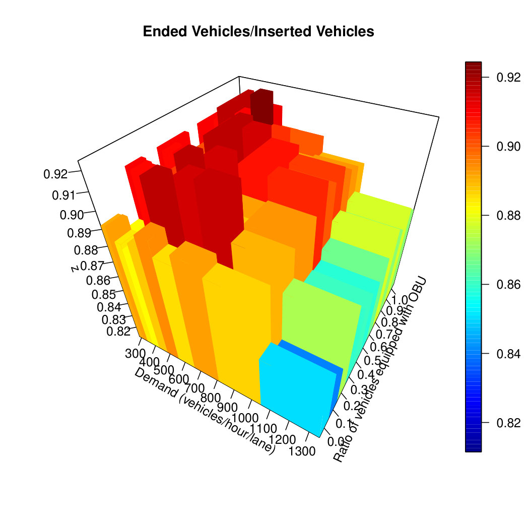 Figure 2
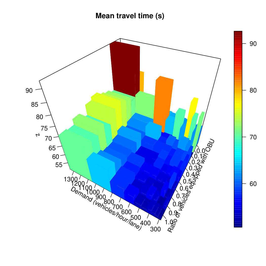 Figure 3
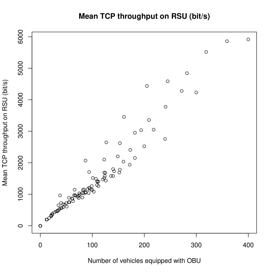 Figure 4
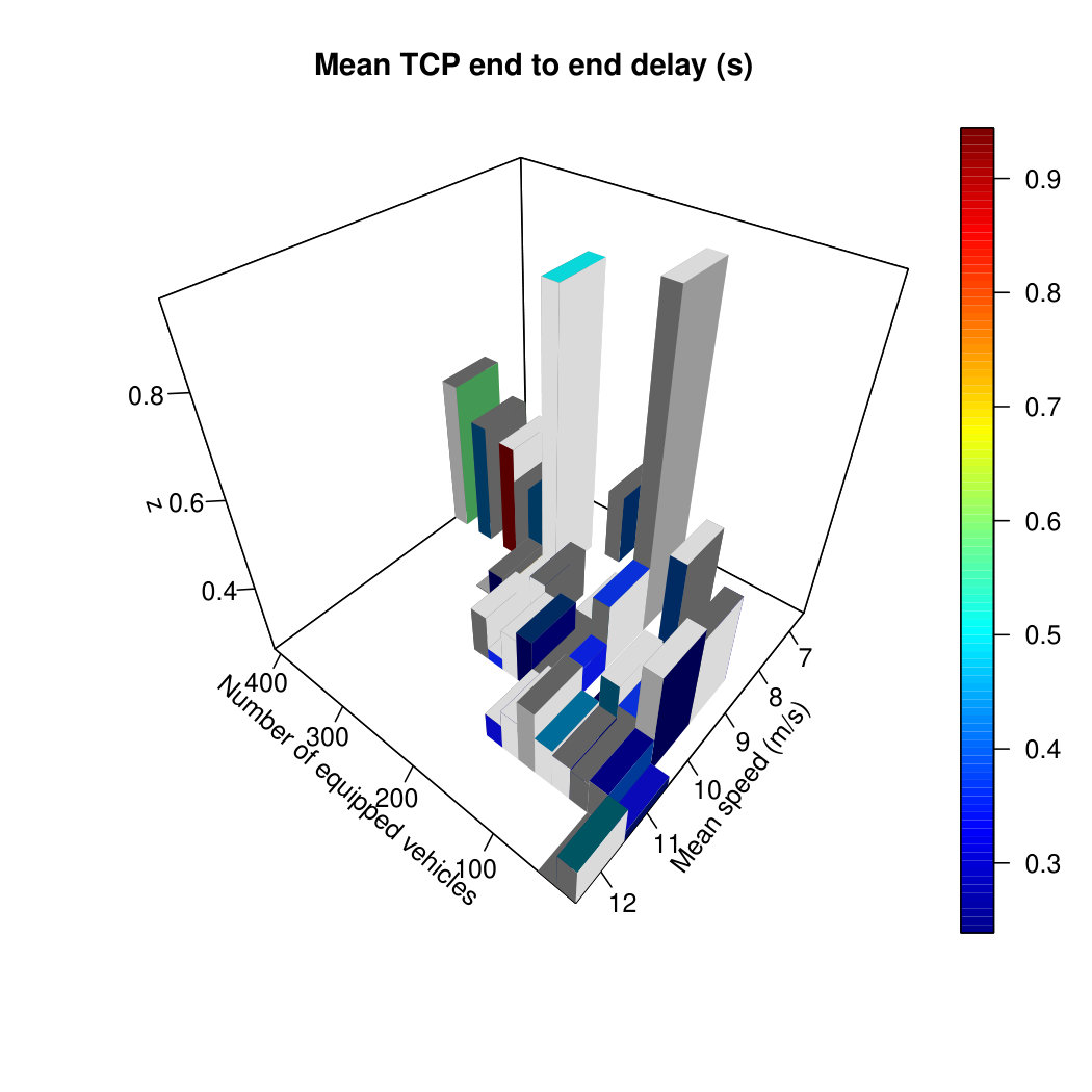 Figure 5
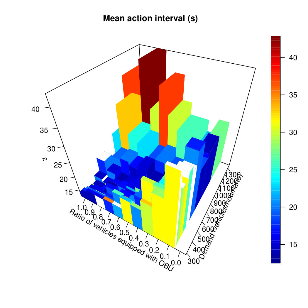 Figure 6
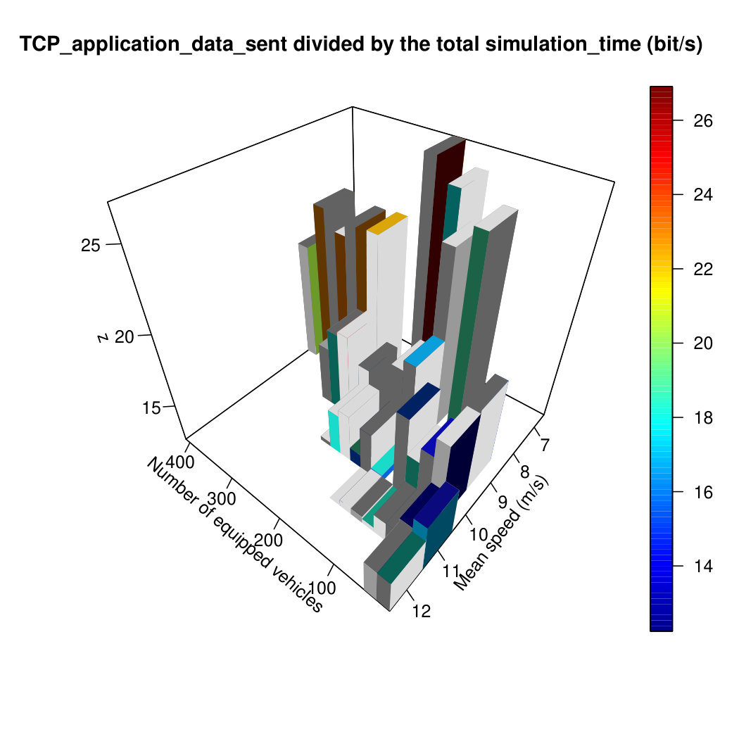 Figure 7
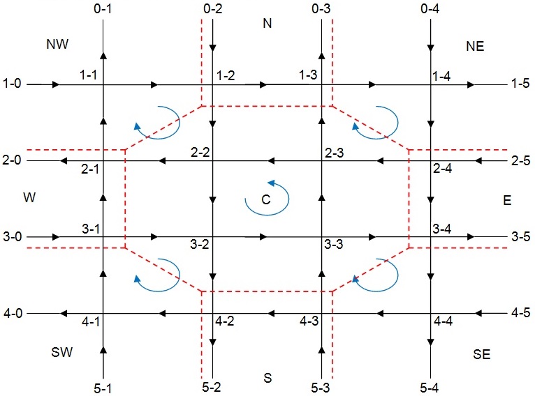 Figure 8
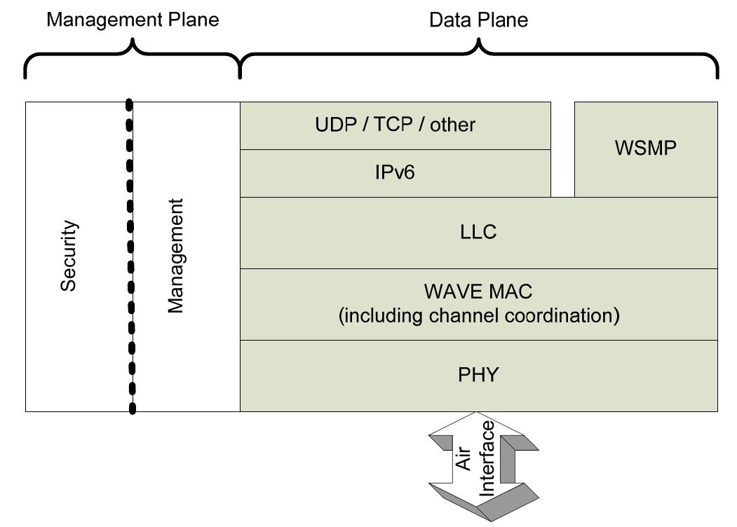 Figure 9
| unique vehicle identifier | |
|---|---|
| c | the IA_to_car_TCP_connection |
| identifier | |
| T | the trajectory which is |
| an ordered map of couples (time, coordinates) | |
| lst | the last time the vehicle data |
| has been received by the IA | |
| fst | the first time the vehicle data |
| has been received by the IA | |
| r | the radius is the distance the car is |
| to the approaching junction | |
| the car position is defined by its radius to the TLS and | |
| the angle this radius is from the (x) axis | |
| s | the state of the car |
| whether the car is coming or leaving the junction | |
| Parameter name | Parameter value |
|---|---|
| vehicle TCP | ms |
| UDP broadcasting interval | ms |
| IA | ms |
| s | |
| 45 s | |
| 8 s | |
| s | |
| s | |
| m | |
| MAC 1609 use service channel | true |
| MAC 1609 bitrate | Mbps |
| MAC 1609 carrier frequency | Hz |
| transmit power | mW |
| application message payload | bytes |
| transceiver sensitivity | dBm |
| Center zone | Each other zone | |
|---|---|---|
| Center zone | 0 | 10 (veh) |
| Each other zone | 15 (veh) | 15 (veh) |
| Center zone | Each other zone | |
|---|---|---|
| Center zone | 0 | 10 (veh) |
| Each other zone | 20 (veh) | 20 (veh) |
| 0% | 20% | 50% | 80% | |
|---|---|---|---|---|
| 25% | 137319 | 147033 | 150718 | 148419 |
| (00)% | (+7.12.5)% | (+9.82.4)% | (+8.11.9)% | |
| 50% | 1373 19 | 149949 | 158319 | 157120 |
| (00) % | (+9.23.4)% | (+15.31.9)% | (+14.52.3) % | |
| 100% | 137319 | 1281151 | 180549 | 187729 |
| (00)% | (-6.711.2)% | (+31.54.1)% | (+36.72.8)% |
| 0% | 20% | 50% | 80% | |
|---|---|---|---|---|
| 25% | 95416 | 84232 | 81718 | 84821 |
| (00%) | (-11.83.5%) | (-14.42.7%) | (-11.22.4%) | |
| 50% | 95416 | 83536 | 76417 | 77821 |
| (00%) | (-12.43.8%) | (-19.92.1%) | (-18.42.5%) | |
| 100% | 95416 | 96280 | 58343 | 51727 |
| (00%) | (+0.98.7%) | (-38.94.7%) | (-45.82.9%) |
| 0% | 20% | 50% | 80% | |
|---|---|---|---|---|
| 25% | 413.91.8 | 381.94.3 | 376.03.1 | 380.03.4 |
| (00%) | (-7.71.1%) | (-9.20.8%) | (-8.20.9%) | |
| 50% | 413.91.8 | 381.815.2 | 355.65.0 | 354.94.5 |
| (00%) | (-7.83.8%) | (-14.11.5%) | (-14.21.2%) | |
| 100% | 413.91.8 | 399.630.6 | 302.06.9 | 281.24.6 |
| (00%) | (-3.47.4%) | (-27.01.7%) | (-32.11.2%) |
Peer Reviews
No public reviews on file for this paper yet. If you reviewed it on a platform where reviews are public (OpenReview, ICLR, NeurIPS, ICML), you can paste yours below so the community can read it here.
Videos
No videos yet. Explain this paper in a talk, walkthrough, or lecture? Add one.
A vehicle-to-infrastructure communication based algorithm for urban traffic control
Cyril Nguyen Van Phu1, Nadir Farhi, Habib Haj-Salem, Jean-Patrick Lebacque
Université Paris Est, COSYS, GRETTIA, IFSTTAR, F-77447 Marne-la-Vallée, France
1 corresponding author
Abstract
We present in this paper a new algorithm for urban traffic light control with mixed traffic (communicating and non communicating vehicles) and mixed infrastructure (equipped and unequipped junctions). We call equipped junction here a junction with a traffic light signal (TLS) controlled by a road side unit (RSU). On such a junction, the RSU manifests its connectedness to equipped vehicles by broadcasting its communication address and geographical coordinates. The RSU builds a map of connected vehicles approaching and leaving the junction. The algorithm allows the RSU to select a traffic phase, based on the built map. The selected traffic phase is applied by the TLS; and both equipped and unequipped vehicles must respect it. The traffic management is in feedback on the traffic demand of communicating vehicles. We simulated the vehicular traffic as well as the communications. The two simulations are combined in a closed loop with visualization and monitoring interfaces. Several indicators on vehicular traffic (mean travel time, ended vehicles) and IEEE 802.11p communication performances (end-to-end delay, throughput) are derived and illustrated in three dimension maps. We then extended the traffic control to a urban road network where we also varied the number of equipped junctions. Other indicators are shown for road traffic performances in the road network case, where high gains are experienced in the simulation results.
Index Terms:
intelligent transportation systems, traffic control, intelligent vehicles, vehicular ad hoc networks
I Introduction
I-A Introduction
Penetration rate of communicating vehicles is expected to increase in the next years. Compared to in-road detectors and video sensors, a wireless road side unit (RSU) can collect more detailed vehicle data such as location, speed and acceleration rate, more than once a second, on some hundred meters range and probably at lower cost [1]. This new amount of high resolution data provided by V2X communication enables new traffic signal controls. We present a new reactive algorithm based on V2I communications using WAVE/IEEE 802.11p protocol. Simulation for road traffic and communication networking has been conducted using VEINS framework [2]. This simulation framework led to a performance study of both road traffic and communication protocols. We show that the gain in road traffic performance is significant most of the time, especially in the case of a high penetration rate for vehicles and junctions.
I-B State of the art
In the field of traffic signal control based on vehicular communication, several approaches have been developed in the few last years [3] : over-saturation algorithms which tend to avoid blockages by using V2I communication, gap-out algorithms which terminate the phase green if no vehicle is detected during a gap-out time, and platoon based algorithms which use vehicle clustering to provide acyclic timing plans. Some other approaches tend to minimize cumulative delays.
In [4], a dynamic gap-out algorithm has been presented. Total vehicular delays are minimized and the optimization determines “phase sequence, phase green times, and gap-out times (both dynamic and regular gap-outs).” In [5], a reactive control based on VANET communication is detailed. Different weights are assigned to vehicles depending on their distance to the junction. A timing plan is then computed and applied using these weights.
Some papers have finely evaluated performances of WAVE/IEEE 802.11.p protocols [6], some of them comparing pros and cons of WAVE and alternatives such as LTE [7]. Coupling road traffic and communication simulators have recently been achieved in VEINS [2]. We also report ITETRIS [8] and VSimRTI [9] that declare successful coupled simulation, even if we haven’t been in measure to evaluate these last two softwares in detail. However, in the case of road traffic control applications, we did not see communication performance studies with specialized communication simulators.
I-C Paper organization
We aimed in this paper to propose a new traffic light control algorithm, based on V2I communication and evaluated with a fine grained and extended simulation tool, VEINS [2]. We modified VEINS in order to include TCP/IP support over IEEE 802.11p. We present some performance indicators of the WAVE protocol stack in the scenario of this new kind of road traffic control. This paper is organized in four parts. In part I, it has been provided the global context and state of the art in the field of connected traffic light signal control. In part II, a new algorithm is presented for road traffic control. Then simulation scenarii and results are shown for one junction and for a small American like road network in part III. In part IV we open perspectives to future works.
II Connected traffic light signal control
II-A Algorithm description
In this section we describe a new local control algorithm. This control makes some hypothesis on vehicles and infrastructure and is composed of the following subtasks : building a map, electing a vehicle and actuating the TLS.
II-A1 Assumptions
We use the terminology described in [1]. We assume that some junctions of the road network are equipped with traffic light signals (TLS) with communication capabilities. In our case the communication protocol is IEEE 802.11p coupled with the Internet Protocol version 4 (IPv4) and the Transmission Control Protocol (TCP). TCP adds transport services to IEEE 802.11.p, such as a reliable and ordered delivery of byte streams [10]. It is used in conjunction with IP which provides network routing services. Hence, we suppose that some TLS are able to communicate with the TCP/IP protocols over IEEE 802.11p and we consider it as an Intersection Agent (IA). Similarly, we suppose that some cars are equipped with the same communication capabilities and are also able to localize themselves, for example with GPS modules which provide in addition global time synchronization. We call them equipped vehicles or Vehicle Agents (VA) [1].
II-A2 Dynamic Maps
With such capabilities, the IA can build a map of the connected vehicles coming and leaving the junction. Similarly each vehicle agent (VA) builds a map of the IAs approaching or leaving it in its communication range. To achieve this, we designed and programmed a map module in OMNET++ [11]. For the map of the vehicles, the coordinates system is relative to the earth. Instead, for the map of the IAs, the coordinates system is relative to the concerned vehicle position. This change of coordinates enables the use of the same module for IAs map and vehicles map. The maps are dynamic; they are updated periodically each time a message is received for the IA, and triggered on timer for the vehicles. Map’s data that are older than a given time, named here , are cleared.
An IA signals itself by broadcasting its IP address and coordinates via UDP protocol. Once the IA announced, the vehicles equipped with UDP client build a local map of all the IAs in their communication range. These vehicles then elect the closest IA approaching. So, the vehicles know their relative positions to the closest junction approaching, without need for communication with the IA anymore. Once close to the elected junction, the vehicles open a TCP connection with the IA.
After the TCP connection with the elected IA is established, all vehicles approaching the junction send periodically their position to the IA, each message being timestamped, with a time period named here . These vehicles data received by the IA enable the build of a map indexed by a unique vehicle identifier, described in TABLE I. Among the different fields of the map, we notice the state of the vehicle (approaching or leaving the junction) which is computed using the positions of vehicles and TLS.
II-A3 Election
We say the road state and a given junction map are synchronized when all vehicles in the junction map have been detected in the last seconds. Periodically, every time and when the junction map is synchronized, the IA computes the lead vehicles on the approaching edges. In our case, we suppose that the junctions have only two incoming edges, each edge having one lane. So there can be two lead vehicles maximum in our case. The two incoming edge priorities alternate every , where is the duration of the TLS periodic program. A vehicle among lead vehicles from incoming edges is elected with the Algorithm 1. If the Algorithm 1 runs successfully, the IA sends a message to the elected vehicle. Otherwise the RSU will try to elect a vehicle after a time.
II-A4 Action
The elected vehicle has now the power to set the TLS to a favorable state, which is green light for the edge on which it is moving and red light for other edges. To do this, the elected vehicle sends a message to the IA with its established TCP connection. We set a minimum and a maximum duration for a given TLS state : and . If no state switch has happened during time, the state of the TLS is automatically changed. Similarly, the state of the TLS must remain the same for at least . With the we ensure stability. With the we ensure dynamics of the states and avoid blockages of the TLS. As we set , if no vehicle is connected near a junction, then the associated TLS will follow an open loop cyclic program with period. Once the connected vehicles know they are leaving the junction (with GPS and local map but not with communication means), they disconnect after they reach a given distance away from the junction.
The process starts again for the next junction and so on.
II-B Properties of the algorithm
II-B1 Property 1
The local control is safe because the control is done by means of a TLS which never gives green light simultaneously to antagonistic phases.
II-B2 Property 2
It is not necessary for a vehicle to be equipped to pass the junction.
II-B3 Property 3
As the control tends to minimize delays for equipped vehicles, communicating equipments of vehicles are encouraged. As the control presents gains for the road traffic, communicating equipments of junctions are encouraged.
II-B4 Property 4
When no vehicle is equipped near an equipped junction, the for a state induces that the TLS runs half time red and half time green light. It is equivalent to a simple open loop cyclic TLS program.
II-C Implementation
We used VEINS Framework [2] which includes SUMO [12] as microscopic traffic simulator and OMNET++ [11] as communication network simulator. We modified and extended VEINS Framework in order to get TCP/IP support over IEEE 802.11p. To do this, “inet” models and Veins framework have been integrated and connected together.
Some application modules have been written : map, car, road side unit, TCP client and server, UDP client and server applications, which implement the algorithm described above. Commands to control the TLS states have been added. The MAC1609 module of VEINS framework module has been modified to connect TCP/IP to IEEE 802.11p layers.
III Simulation results
We simulated a few runs with different seeds, each run being reproducible. We present statistical results for the road network case with 20 different simulations and preliminary results (one typical run) for the one junction case.
III-A One Junction with connected TLS
III-A1 Scenario for one junction
We used the following road network, composed of one junction, with one lane incoming edges of 300 m length. We varied the demand which is the number of vehicles (uniformally inserted in time) per lane per hour. For each of this traffic demand, we varied the ratio of equipped vehicles with on board unit (OBU).
The total simulation time is 600 s. For the communication and the control algorithm, the main parameters are described in TABLE II.
III-A2 Simulation measurements
For the communication we have measured the mean TCP end-to-end delay, TCP throughput on RSU (Road Side Unit) and the amount of TCP application data sent divided by the total simulation time. We define the simulation indicator mean TCP end-to-end delay as the sum of all packet delays divided by the number of packets exchanged. The throughput on RSU is the sum of TCP application packet (successfully received) sizes divided by the simulation time. A given number of communicating hosts may be the result of different combinations of a demand multiplied by a ratio of equipped vehicles. For example, equipped vehicles of vehicles in total, gives the same number as equipped vehicles of a total of vehicles.
In figure 2 we can see that the amount of TCP application data sent by the nodes increases as the mean vehicle speed decreases. We assume that as the mean vehicle speed is low, the communicating vehicles remain connected longer, and then they send more messages.
In figure 3, we see that the mean TCP end-to-end delay can be as high as when vehicle speed is low (about ). We know from figure 2 that there are more data sent by the nodes when mean speed is low. We suppose that as there are more messages sent in case of low speeds, the mean TCP end-to-end delay will be higher.
The order of magnitudes of end-to-end delay is similar to the ones exposed in [7]. Clearly, in figure 4, the throughput on RSU is increasing linearly with the number of communicating vehicles.
For the road traffic, we measured the ratio of the ended vehicles by the inserted vehicles, and the mean travel time. We observe on figure 5 that the ratio of the ended vehicles by the inserted vehicles increases when the demand decreases and the ratio of equipped vehicles increases. For a given ratio of equipped vehicles, as the road traffic demand increases, the ratio of the ended vehicles by the inserted vehicles decreases. For a given demand, this ratio increases with the number of equipped vehicles.
In figure 6, for a given demand, the mean travel time decreases as the number of equipped vehicles increases. This should encourage the spreading of vehicle communication capabilities. For a fixed demand, the difference in travel time between the worst and the best cases for a total distance of 600 m, may be as high as 20 seconds.
For the actuator, we define the mean action interval as the mean time interval between two consecutive changes of traffic lights state. We observe in figure 7 that the traffic light state is stable for high traffic demand combined with a high equipped vehicle penetration rate. This minimizes the total yellow time of the traffic light, and then maximizes the junction capacity. For a low demand combined with a high equipped vehicle penetration rate, the control is more reactive.
III-B Traffic control at the road network level
III-B1 Scenario for the road network
We consider here an American like network with 16 junctions and 40 edges of length 500 m each. This is the same network considered in [14], where centralized and decentralized road traffic controls have been combined. Each edge has one lane. We varied the number of equipped junctions : 25%, 50%, 100%; and the penetration rate of equipped vehicles : 20%, 50%, 80%. We defined nine zones in the network. The simulated time is s and the communication parameters are the same as in the “one junction” scenario.
We used SUMO “origin and destination edges instead of a complete list of edges. In this case the simulation performs fastest-path routing based on the traffic conditions found in the network at the time of departure/flow begin.”[15]. The road traffic demand is given in tables III and IV.
III-B2 Simulation results
(Table V, Table VI and Table VII) We compare our algorithm with an open loop fixed cycle TLS program, where the same cycle time is considered in both cases. This open loop cyclic control can also be achieved with zero communicating vehicles in our algorithm. The gain of our algorithm in terms of ended vehicles can be very high, as much as 30%. The gain in running vehicles can be as high as 40% and the gain in mean travel time can reach 30%.
We observe that when the penetration rate is 20% and when all junctions are equipped, the algorithm is not efficient. We suppose that as there are less vehicles communicating, less vehicles manage to connect in time (before having passed the junction). It then could be possible that the TLS map is not a good image of the real traffic. This could explain why the cycles of the TLS are not globally adequate. When all junctions are equipped, this can even be globally disturbing.
IV Conclusions
We presented a new V2I based TLS control algorithm, with its design, implementation and performance study for communication and road traffic. Compared to an open loop cyclic TLS program, we showed that the presented algorithm features high gains in most of the configurations. However, in few cases, where low penetration rate for vehicles is combined with high ratio of equipped junctions, it seems that the algorithm is not efficient and produces some losses. An hypothesis for this phenomenon has been proposed. Future works could benefit from a mix of microscopic and macroscopic road traffic controls, based on vehicular communication networking.
The reference list from the paper itself. Each links out to its DOI / PubMed record.
- 1[1] R. Florin and S. Olariu, “A survey of vehicular communications for traffic signal optimization,” Veh. Commun. , vol. 2, no. 2, pp. 70–79, Apr. 2015. [Online]. Available: http://dx.doi.org/10.1016/j.vehcom.2015.03.002 · doi ↗
- 2[2] C. Sommer, R. German, and F. Dressler, “Bidirectionally Coupled Network and Road Traffic Simulation for Improved IVC Analysis,” IEEE Transactions on Mobile Computing , vol. 10, no. 1, p. 3–15, January 2011.
- 3[3] N. J. Goodall, B. L. Smith, and B. B. Park, “Traffic signal control with connected vehicles,” Transportation Research Record: Journal of the Transportation Research Board , vol. 2381, pp. 65–72, 2013.
- 4[4] S. J. Agbolosu-Amison, I. Yun, and B. B. Park, “Quantifying benefits of a dynamic gap-out feature at an actuated traffic signalized intersection under cooperative vehicle infrastructure system,” KSCE Journal of Civil Engineering , vol. 16, no. 3, pp. 433–440, 2012. [Online]. Available: http://dx.doi.org/10.1007/s 12205-012-1495-7 · doi ↗
- 5[5] S. Kwatirayo, J. Almhana, and Z. Liu, “Optimizing intersection traffic flow using vanet,” in 2013 IEEE International Conference on Sensing, Communications and Networking (SECON) , June 2013, pp. 260–262.
- 6[6] Y. Wang, A. Ahmed, B. Krishnamachari, and K. Psounis, “Ieee 802.11p performance evaluation and protocol enhancement,” in 2008 IEEE International Conference on Vehicular Electronics and Safety , Sept 2008, pp. 317–322.
- 7[7] Z. Hameed Mir and F. Filali, “Lte and ieee 802.11p for vehicular networking: a performance evaluation,” EURASIP Journal on Wireless Communications and Networking , vol. 2014, no. 1, p. 89, 2014. [Online]. Available: http://dx.doi.org/10.1186/1687-1499-2014-89 · doi ↗
- 8[8] V. Kumar, L. Lin, D. Krajzewicz, F. Hrizi, O. Martinez, J. Gozalvez, and R. Bauza, “itetris: Adaptation of its technologies for large scale integrated simulation,” in 2010 IEEE 71st Vehicular Technology Conference , May 2010, pp. 1–5.