Chiral magnetoresistance in Pt/Co/Pt zigzag wires
Yuxiang Yin, Dong-Soo Han, June-Seo Kim, Reinoud Lavrijsen, Kyung-Jin, Lee, Seo-Won Lee, Kyoung-Whan Kim, Hyun-Woo Lee, Henk J. M. Swagten, and Bert, Koopmans

TL;DR
This paper demonstrates the existence of chiral magnetoresistance in Pt/Co/Pt zigzag wires, linking Rashba effect and Dzyaloshinskii-Moriya interaction to domain wall resistance, and provides a method to quantify these effects.
Contribution
It introduces a novel measurement of chiral magnetoresistance in zigzag wires and correlates Rashba effect, DMI, and exchange interactions through experimental and theoretical analysis.
Findings
Chirality-dependent domain wall resistance observed.
Quantitative agreement with Rashba model theory.
Independent determination of Rashba and DMI strengths.
Abstract
The Rashba effect leads to a chiral precession of the spins of moving electrons while the Dzyaloshinskii-Moriya interaction (DMI) generates preference towards a chiral profile of local spins. We predict that the exchange interaction between these two spin systems results in a 'chiral' magnetoresistance depending on the chirality of the local spin texture. We observe this magnetoresistance by measuring the domain wall (DW) resistance in a uniquely designed Pt/Co/Pt zigzag wire, and by changing the chirality of the DW with applying an in-plane magnetic field. A chirality-dependent DW resistance is found, and a quantitative analysis shows a good agreement with a theory based on the Rashba model. Moreover, the DW resistance measurement allows us to independently determine the strength of the Rashba effect and the DMI simultaneously, and the result implies a possible correlation between the…
Click any figure to enlarge with its caption.
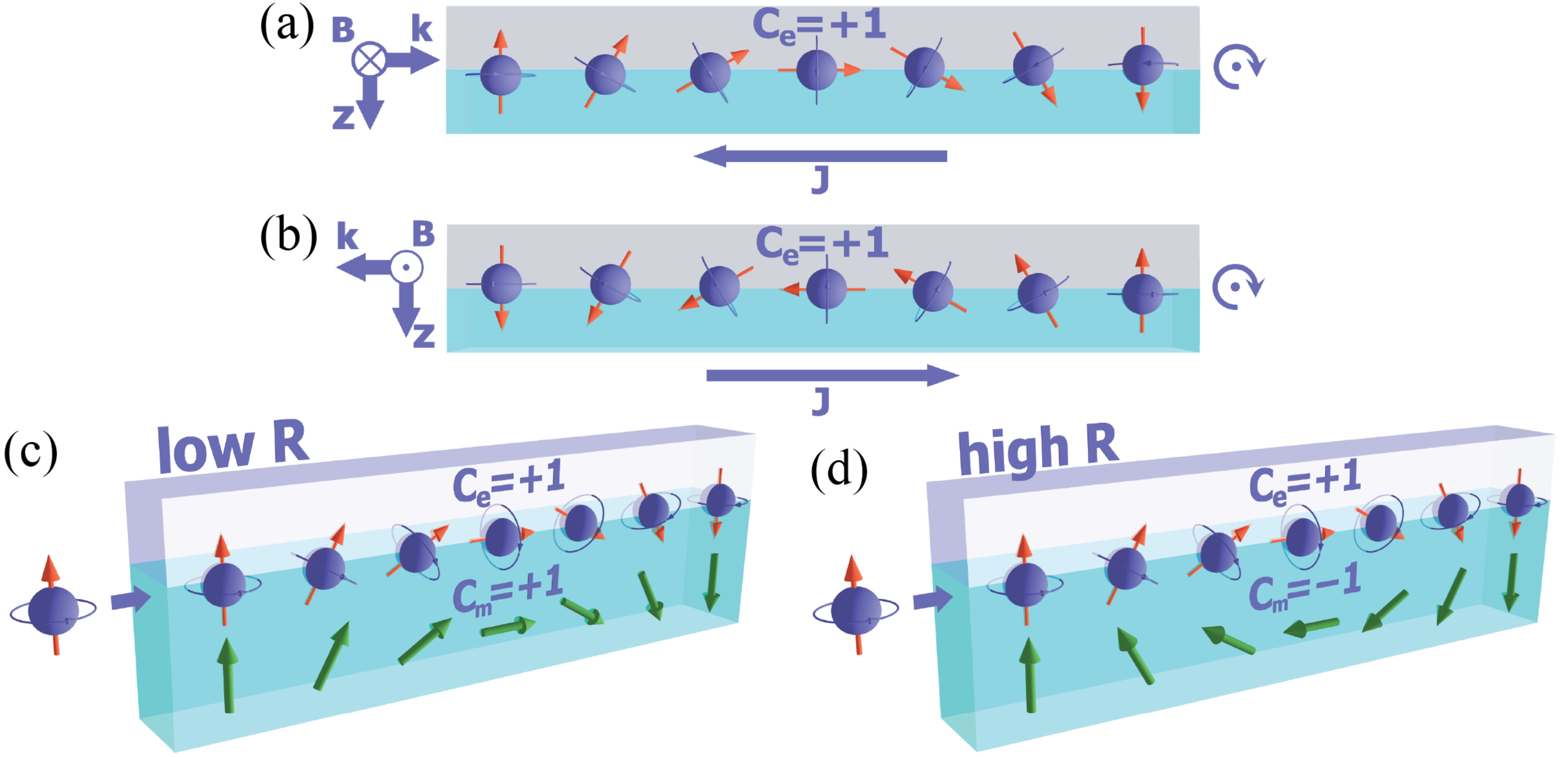 Figure 1
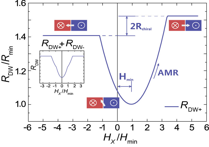 Figure 2
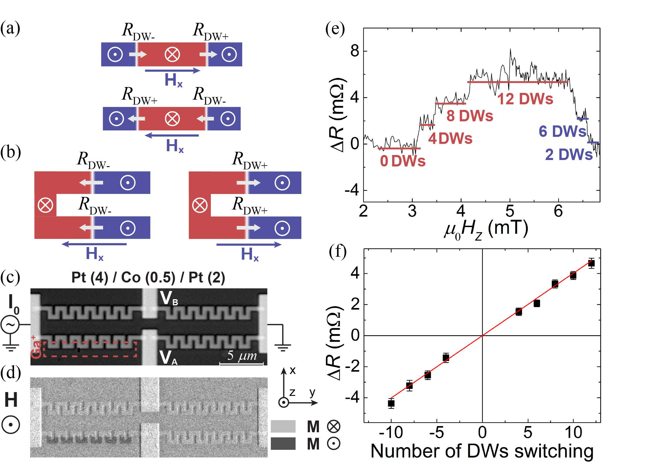 Figure 3
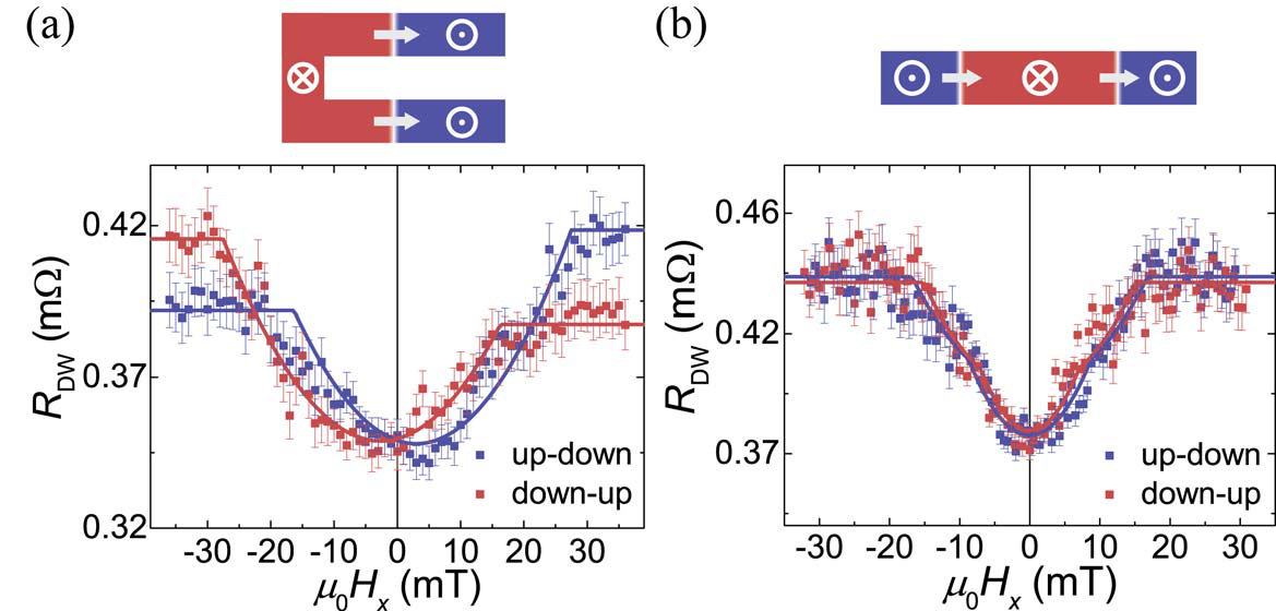 Figure 4
 Figure 5
Peer Reviews
No public reviews on file for this paper yet. If you reviewed it on a platform where reviews are public (OpenReview, ICLR, NeurIPS, ICML), you can paste yours below so the community can read it here.
Videos
No videos yet. Explain this paper in a talk, walkthrough, or lecture? Add one.
Chiral magnetoresistance in Pt/Co/Pt zigzag wires
Yuxiang Yin
Dong-Soo Han
June-Seo Kim
Reinoud Lavrijsen
Department of Applied Physics, Center for NanoMaterials, Eindhoven University of Technology, PO Box 513, 5600 MB Eindhoven, The Netherlands
Kyung-Jin Lee
Department of Materials Science and Engineering, Korea University, Seoul 02841, Korea
KU-KIST Graduate School of Converging Science and Technology, Korea University, Seoul 02841, Korea
Seo-Won Lee
Department of Materials Science and Engineering, Korea University, Seoul 02841, Korea
Kyoung-Whan Kim
Center for Nanoscale Science and Technology, National Institute of Standards and Technology, Gaithersburg, Maryland 20899, USA
Hyun-Woo Lee
PCTP and Department of Physics, Pohang University of Science and Technology, Pohang 37673, Korea
Henk J. M. Swagten
Bert Koopmans
Department of Applied Physics, Center for NanoMaterials, Eindhoven University of Technology, PO Box 513, 5600 MB Eindhoven, The Netherlands
Abstract
The Rashba effect leads to a chiral precession of the spins of moving electrons while the Dzyaloshinskii-Moriya interaction (DMI) generates preference towards a chiral profile of local spins. We predict that the exchange interaction between these two spin systems results in a ‘chiral’ magnetoresistance depending on the chirality of the local spin texture. We observe this magnetoresistance by measuring the domain wall (DW) resistance in a uniquely designed Pt/Co/Pt zigzag wire, and by changing the chirality of the DW with applying an in-plane magnetic field. A chirality-dependent DW resistance is found, and a quantitative analysis shows a good agreement with a theory based on the Rashba model. Moreover, the DW resistance measurement allows us to independently determine the strength of the Rashba effect and the DMI simultaneously, and the result implies a possible correlation between the Rashba effect, the DMI, and the symmetric Heisenberg exchange.
In a magnetic system with inversion symmetry breaking combined with spin-orbit coupling (SOC), a variety of chirality-related phenomena occur. For instance, due to the Rashba effect Bychkov and Rashba (1984), the spins of the conduction electrons flowing at an interface are subject to an effective in-plane magnetic field due to the relativistic SOC, resulting in spin precession around the field during its transport. In this case, the direction of the magnetic field depends on the electron flow direction. In contrast, the precession of the conduction spins, as can be seen from comparing Figs. 1(a) and 1(b), is independent of the flow direction and shares the same rotational sense (denoted by a chirality of electrons, ) Lounis et al. (2012). Apart from the chiral behavior of the conduction spins, the chiral nature of localized spins has recently been discovered in ferromagnetic materials with inversion asymmetry and SOC. This gives rise to the Dzyaloshinskii-Moriya interaction (DMI) Dzyaloshinsky (1958); Moriya (1960) leading to a chiral spin texture of the localized spins (), manifested as Néel type magnetic domain walls (DWs) Chen et al. (2013) and magnetic skyrmions Woo et al. (2016), which are crucial to the future design of spintronic devices.
Although these two effects originate in different spin systems, one can speculate about their interplay through exchange interaction between the conduction and localized spins Jué et al. (2015); Kim et al. (2013); Pyatakov and Zvezdin (2014). This results in a magnetoresistance (MR) which arises when the conduction electron spins propagate with a fixed chirality due to Rashba-type SOC and interact with the chiral DMI-induced magnetic texture. As shown in Figs. 1(c) and 1(d), this should lead to lower (higher) resistance when is identical (opposite) to . This MR can be termed as ‘chiral MR’, since the magnitude of the MR varies for spin textures with different chiralities. However, a direct experimental evidence of this chiral MR is not found so far. Therefore, the measurement of chiral MR could not only enrich the spectrum of chirality-related physical phenomena but also shed light on the debated roles of the DMI and Rashba effect for fast current-driven DW motion Miron et al. (2011) and other SOC-related phenomena Kobs et al. (2011); Nakayama et al. (2013). Besides, this type of magnetoresistance provides further insights in engineering magnetic thin film systems with specifically desired chiral entities for future applications in nanoelectronics.
In this work, a chiral MR is observed by measuring the magnetic DW resistance, which probes the interaction between an electric current and a magnetic DW. The magnetic DW is a twisted spin structure whose chirality can be altered by an external field Ryu et al. (2013), making it a perfect playground for measuring the chiral MR. We report results on a controllable, specifically designed DW system where chiral DWs are created by modifying the perpendicular magnetic anisotropy of a zigzag wire using a focused ion beam, and applying an in-plane field for switching between the DW chiralities. It is found that the DW resistance varies with the chirality of DWs, and the observed behavior can be described by a theoretical model based on the Rashba Hamiltonian, lending strong support to our interpretation of a chirality-dependent interaction between the conduction and localized spins.
We first analytically derive the chiral MR explained in Fig. 1. For better legibility, we exaggerate the effect of Rashba SOC but mostly ignore the effect of exchange interaction between the conduction electrons and local magnetization. However, in real systems, the exchange interaction is much higher than the Rashba interaction. Thus we adopt this regime and start from the Rashba Hamiltonian added to a strong exchange interaction . Here characterizes the preferred spin precession rate, the planck constant, the electron mass, the electron momentum, the interface normal, and the spin Pauli matrix, the exchange energy, and the direction of magnetization. The Rashba model captures core effects of the strong SOC combined with inversion symmetry breaking at the interface Park et al. (2013). Recently, it was predicted Kim et al. (2013) that linear effects of the chirality can be obtained from non-chiral theories simply by replacing , where is the current flow direction, with the so-called chiral derivative . Here, we apply the chiral derivative to the DW resistance derived by Levy and Zhang Levy and Zhang (1997), , where is the DW resistivity. By assuming a DW with Walker profile Schryer and Walker (1974) and after some algebra (see Supplementary Material), we obtain , where is the DW width, the DW in-plane angle, and refers to up-down and down-up DW’s, respectively. The DW is a Bloch wall when and a Néel wall when . The second term in is the chiral DW resistance, which changes its sign when the DW chirality changes.
Apart from the contribution from the inhomogeneity of the magnetic texture, the resistance also depends on the local magnetization direction itself due to anisotropic magnetoresistance (AMR) Kobs et al. (2011). Based on AMR, the resistance is lower (higher) where the magnetization direction is perpendicular (parallel) to the current flowing direction. The theory of AMR implies that the MR is proportional to . After adding the AMR contribution to , the total DW resistance can be written as
[TABLE]
where is a proportionality constant of AMR and is the chiral DW resistance.
Experimentally, can be tuned by applying an in-plane field which is perpendicular to the DW. To determine the relation between and , we start from the energy functional Thiaville et al. (2012), where is the exchange stiffness, the perpendicular anisotropy, the demagnetizing field, the DMI parameter, and the saturation magnetization. Applying the Walker ansatz reduces the energy functional to a function of only. The energy minimizing condition gives
[TABLE]
Here, we ignore the dependence of on , which is too weak to affect the analysis (see Supplementary Material). By substituting Eq. (2) into Eq. (1), we plot in Fig. 2 the resulting as a function of , where and are the values where the DW resistance is minimal. Three observations can be made: (i) There is an increase of the resistance when increases. This is expected since the field pulls the DW into a Néel state, thereby increasing the AMR. (ii) For a finite DMI, the DW is in between Bloch and Néel type for , i.e., Franken et al. (2014); Emori et al. (2014). This tilt angle depends on the magnitude of the DMI, allowing us to determine the DMI energy density , where is the effective DMI field, by measuring the field shift (see Supplementary Material). (iii) The most striking feature from this theory is a difference in (indicated by in Fig. 2) at high applied in-plain fields showing the unique dependence of the DW resistance on chirality. It is therefore very useful to measure the in-plane field dependence of DW resistance, since it allows us to independently determine the strength of DMI and the Rashba effect simultaneously (see Supplementary Material).
To possibly measure , one could naively use a straight Pt/Co/Pt nanowire as reported earlier Franken et al. (2012); see Fig. 3(a). Here, the red part indicates the region irradiated by Ga ions which reduce the perpendicular magnetic anisotropy and allow the nucleation of DWs on two sides Franken et al. (2011a). However, this straight wire is not suitable for measuring the chiral resistance, as we will experimentally show later on, because the DW pair has an opposite chirality when applying a high in-plane field. Thus, the total chiral resistance is averaged out, as shown in the inset of Fig. 2. In order to overcome this difficulty, we develop an alternative, zigzag strip [Fig. 3(b)]. The zigzag together with anisotropy modifications allows for two DWs with the same chirality where is controllable by the in-plane field.
Figure 3(c) and 3(d) show Kerr microscope images of the sample structure used for the chiral DW resistance measurements. A perpendicularly magnetized stack Pt(4 nm)/Co(0.5 nm)/Pt(2 nm) is employed to provide a sizable DMI Je et al. (2013). Here, the red dashed area indicates the Ga+ irradiation region with a dose of cm*-2* at 30 keV. Four m wide zigzag wires are patterned using electron-beam lithography and a lift-off, in the form of a Wheatstone bridge to improve the signal-to-noise ratio. We apply an AC current with a constant strength mA at a frequency of Hz, and measure the differential output signal with a lock-in amplifier [See Fig. 3(c) for and ], which can be used to calculate the change of the resistance in the wire due to the DWs.
Figure 3(e) shows the resistance change in the wire for DWs whose number is controllable. In the measurement, the magnetization is first saturated by applying mT, then a positive magnetic field is swept from 0 mT to 10 mT. A stepwise increase of is observed, corresponding to the appearance of DWs. The coercive fields of the irradiated domains show small statistical variations so that not all DWs appear simultaneously. The number of DWs nucleated can easily be determined by Kerr microscopy (see Supplementary Material). The solid red and blue lines indicate ranges where the number of DWs is constant, and successive increases (decreases) of DWs is indicated by red (blue). In Fig. 3(f), is plotted as function of the number of DWs present, showing a linear dependence as expected. From the linear fit, we extract a resistance change of per DW, which is comparable to our previous report Franken et al. (2012).
The procedure to measure the chiral DW resistance is as follows: (i) The field at which we want to measure is set, (ii) we saturate the sample at mT, (iii) a field of mT is applied and is measured using a lock-in amplifier, (iv) we carefully increase to nucleate a few domains, (v) is then reduced back to mT and is measured, and the voltage difference is recorded. Steps (iii)-(v) are then repeated to systematically track the resistance change as a function of number of DW’s giving an accurate measure of at a given . This procedure is then repeated for every . In order to quantitatively compare the measured as a function of with the theoretical model we should consider the DW resistance in the magnetic Co layer, which can be obtained from by using a Fuchs-Sondheimer model Franken et al. (2011a) to exclude current shunting through the Pt layers.
The measured of the Pt/Co/Pt zigzag and straight wires as a function of in-plane field are shown in Figs. 4(a) and 4(b), respectively. The blue and red squares represent the magnetic switching with different polarities (up-down and down-up). For the zigzag wire, we observe that rises as increases, owing to an increase of AMR when a Bloch wall transforms into a Néel wall. In addition, we clearly observe a field shift, which originates mainly from the DMI Je et al. (2013); Franken et al. (2014); Emori et al. (2014) and partially from the chiral MR (see Supplementary Material). As expected from the chirality of the DW spin structures, the field shift has an opposite sign for DWs of opposite polarity. Another prominent observation in Fig. 4(a) is that the magnitude of the DW resistance depends on the chirality of Néel walls, which can be varied by reversing the in-plane field or changing the polarity of the Néel walls. As can be seen, a substantial difference in resistance at saturation is observed in the zigzag wire, as expected from our theoretical prediction. Such difference in resistance for opposite chirality of Néel walls is strongly supported by the results from the straight wire, where all chirality-induced effects should be canceled out due to the opposite chirality of two DWs under an in-plane field. Indeed, in contrast to the results from the zigzag wire, no significant difference between the up-down and down-up data sets are seen in Fig. 4(b). This is additionally confirmed by performing a fit to the data as further explained in Supplementary Material, showing a good agreement with the behavior illustrated in the inset of Fig. 2. Consequently, we can conclude that the aforemeasured resistance difference results from the chirality of DWs.
Next, we estimate the strength of the Rashba effect and DMI by fitting to our theoretical model [Eq. (1)]. We assume standard material parameters for Co as used in our previous works Franken et al. (2011b, 2014): J/m, kA/m, effective anisotropy MJ/, and nm. The fits are plotted in Fig. 4(a) as blue and red lines, which is in a good agreement with the experimental data. Since we fit these two data sets separately, we extract the free parameters by taking the average of the up-down and down-up data: mT, , , , mT, and (the parameter errors are presented in Supplementary Material). The AMR parameter is similar to the value obtained from a micromagnetic simulation Manago et al. (2009); Hassel et al. (2011) (see Supplementary Material), demonstrating that the increase of DW resistance at small field is indeed due to AMR. The estimated is comparable to the previously reported value as measured in a similar Pt/Co/Pt stack Kobs et al. (2011). For the Rashba coefficient, a first-principles calculation predicts for a Pt/Co interface. This value is not representative for our experimental system since a Pt/Co/Pt stack is used where two opposing Pt/Co and Co/Pt interfaces need to be taken into account leading to much smaller effective Rashba coefficient Kim et al. (2013); Freimuth et al. (2014); Lavrijsen et al. (2012). Indeed, we extract a which only amounts up to 9.6 % of the quoted theoretical value.
Since we can independently measure the strength of the Rashba effect and DMI, sharing common origins (SOC and structural inversion asymmetry) in the same system, we can explore their correlation possibly shedding light on their entangled role in SOC-related phenomena Kobs et al. (2011); Nakayama et al. (2013). For example, it is shown that the Rashba model implies the interfacial DMI energy density is proportional to a Rashba coefficient in a form of Kim et al. (2013)
[TABLE]
Using the values obtained from our fitting, we find J/m, which is of the same order of magnitude as the exchange stiffness of bulk Co Franken et al. (2011b). Systematic errors of and could arise from the uncertainty in and due to the Ga irradiation, which we do not separately address in the current work. However, since and both scales with , the errors do not affect the verification of Eq. (3). This agreement found from the Rashba model and using our experimentally extracted parameters implies that the DMI in our sample may originate from the Rashba-induced twisted Ruderman-Kittel-Kasuya-Yosida interaction Fert and Levy (1980); Kim et al. (2013); Pyatakov and Zvezdin (2014); Imamura et al. (2004) rather than the original explanation by Moriya Moriya (1960) based on a superexchange model. Quantitatively, the Rashba strength is proportional to the ratio of symmetric and antisymmetric exchange. It implies that the DMI may be tuned by controlling the strength of the Rashba effect (e.g., by applying a electric field Liu and Vignale (2011); Barnes et al. (2014)) or the strength of the symmetric exchange. In passing, we note that a one-to-one correspondence between the DMI and symmetric exchange was demonstrated very recently using an optical spin-wave spectroscopy Nembach et al. (2015).
Although we used the Rashba model to analyze the chiral DW resistance in view of chiral precession of conduction electron spins, another possible explanation might be found in considering the bulk spin Hall effect (SHE) of Pt. As far as symmetry constraints are concerned, it is not impossible for the SHE to generate the chiral DW resistance, though such theory is not developed yet. Specifically, considering that the SHE is of bulk origin, we do not understand how the chiral DW resistance due to the SHE could match with the DMI, which, in our system, is of interfacial origin. In contrast, the good match between and in our experiment suggests that the chiral DW resistance and the DMI share the common origin.
In summary, we measured the DW resistance on a magnetic zigzag wire and found that it was chirality dependent. This measurement allows us to unambiguously determine the magnitude of the Rashba effect and DMI as independent parameters. A quantitative agreement was found between experiment and theory, supporting the idea that the Rashba effect could be coupled to DMI via the symmetric exchange interaction. Besides its fundamental importance, the chiral DW resistance opens up possibilities of designing energy-efficient magnetic DW devices, for example, if we combine it with recently proposed electric-field control of DW chirality Chen et al. (2014).
Supplementary Material
See Supplementary Material for 1. Derivation of chiral DW resistance. 2. DW width variation. 3. Quantification of the DMI by the field shift. 4. The real-time DW resistance measurement. 5. Determination of the anisotropic magnetoresistance. 6. Straight Pt/Co/Pt wire: fitting the experimental data. 7. DW resistance measurement of other samples. 8. DW resistance measurement of Pt/Co/AlOx.
Acknowledgement
The authors acknowledge P. Haney, C.-Y. You, M. D. Stiles, and J. McClelland for critical reading of the manuscript. This work is part of the research programme of the Foundation for Fundamental Research on Matter (FOM), which is part of the Netherlands Organisation for Scientific Research (NWO). K.W.K. acknowledges support under the Cooperative Research Agreement between the University of Maryland and the National Institute of Standards and Technology, Center for Nanoscale Science and Technology, Grant No. 70NANB10H193, through the University of Maryland. K.W.K also acknowledges support by Basic Science Research Program through the National Research Foundation of Korea (NRF) funded by the Ministry of Education (2016R1A6A3A03008831). H.W.L was supported by the National Research Foundation of Korea (NRF) (Grants No. 2011-0030046 and No. 2013R1A2A2A05006237). K.J.L was supported by the NRF (Grants No. 2011-0027905 and No. NRF-2015M3D1A1070465).
The reference list from the paper itself. Each links out to its DOI / PubMed record.
- 1Bychkov and Rashba (1984) Y. A. Bychkov and E. Rashba, JETP lett. 39 , 78 (1984).
- 2Lounis et al. (2012) S. Lounis, A. Bringer, and S. Blügel, Phys. Rev. Lett. 108 , 207202 (2012).
- 3Dzyaloshinsky (1958) I. Dzyaloshinsky, J. Phys. Chem. Solids 4 , 241 (1958).
- 4Moriya (1960) T. Moriya, Phys. Rev. Lett. 4 , 228 (1960) . · doi ↗
- 5Chen et al. (2013) G. Chen, J. Zhu, A. Quesada, J. Li, A. T. N’Diaye, Y. Huo, T. P. Ma, Y. Chen, H. Y. Kwon, C. Won, Z. Q. Qiu, A. K. Schmid, and Y. Z. Wu, Phys. Rev. Lett. 110 , 177204 (2013) . · doi ↗
- 6Woo et al. (2016) S. Woo, K. Litzius, B. Krüger, M.-Y. Im, L. Caretta, K. Richter, M. Mann, A. Krone, R. M. Reeve, M. Weigand, P. Agrawal, I. Lemesh, M.-A. Mawass, P. Fischer, M. Kläui, and G. S. D. Beach, Nat. Mater. 15 , 501 (2016) .
- 7Jué et al. (2015) E. Jué, C. K. Safeer, M. Drouard, A. Lopez, P. Balint, L. Buda-Prejbeanu, O. Boulle, S. Auffret, A. Schuhl, A. Manchon, I. M. Miron, and G. Gaudin, Nat. Mater. 15 , 272 (2015) . · doi ↗
- 8Kim et al. (2013) K.-W. Kim, H.-W. Lee, K.-J. Lee, and M. D. Stiles, Phys. Rev. Lett. 111 , 216601 (2013) .