Momentum Control of an Underactuated Flying Humanoid Robot
Daniele Pucci, Silvio Traversaro, Francesco Nori

TL;DR
This paper introduces a control framework for underactuated flying humanoid robots, enabling stable flight, contact locomotion, and manipulation by controlling centroidal momentum, verified through simulations on the iCub robot model.
Contribution
It proposes a novel momentum control method for underactuated flying humanoid robots, integrating Whole-Body Control and Aerial Manipulation concepts.
Findings
Stability and convergence of robot momentum are proven using Lyapunov methods.
Simulations on iCub demonstrate the effectiveness of the control approach.
The framework enables trajectory tracking and orientation control in simulation.
Abstract
The paper takes the first step towards the de- velopment of a control framework for underactuated flying humanoid robots. These robots may thus have the capacities of flight, contact locomotion, and manipulation, and benefit from technologies and methods developed for Whole-Body Control and Aerial Manipulation. As in the case of quadrotors, we as- sume that the humanoid robot is powered by four thrust forces. For convenience, these forces are placed at the robot hands and feet. The control objective is defined as the asymptotic stabilization of the robot centroidal momentum. This objective allows us to track a desired trajectory for the robot center of mass and keep small errors between a reference orientation and the robot base frame. Stability and convergence of the robot momentum are shown to be in the sense of Lyapunov. Simulations carried out on a model of the humanoid robot iCub…
Click any figure to enlarge with its caption.
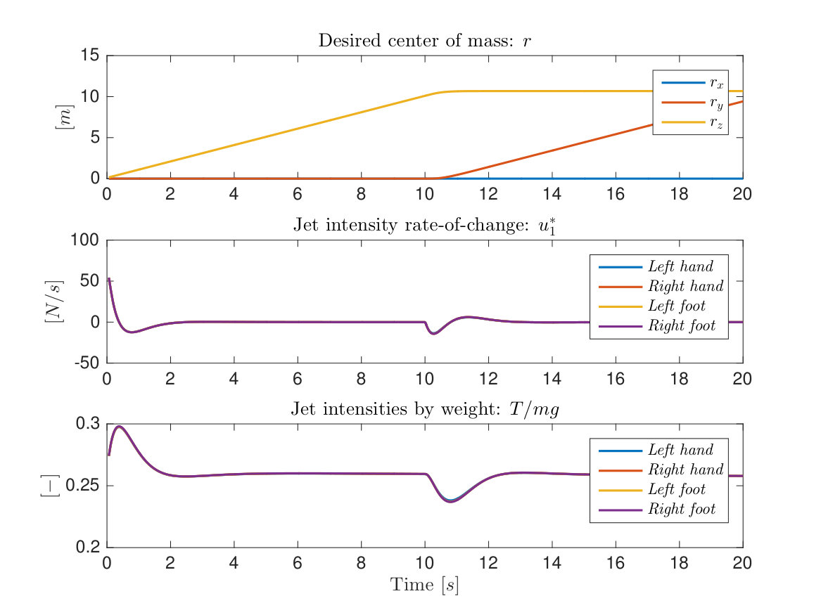 Figure 1
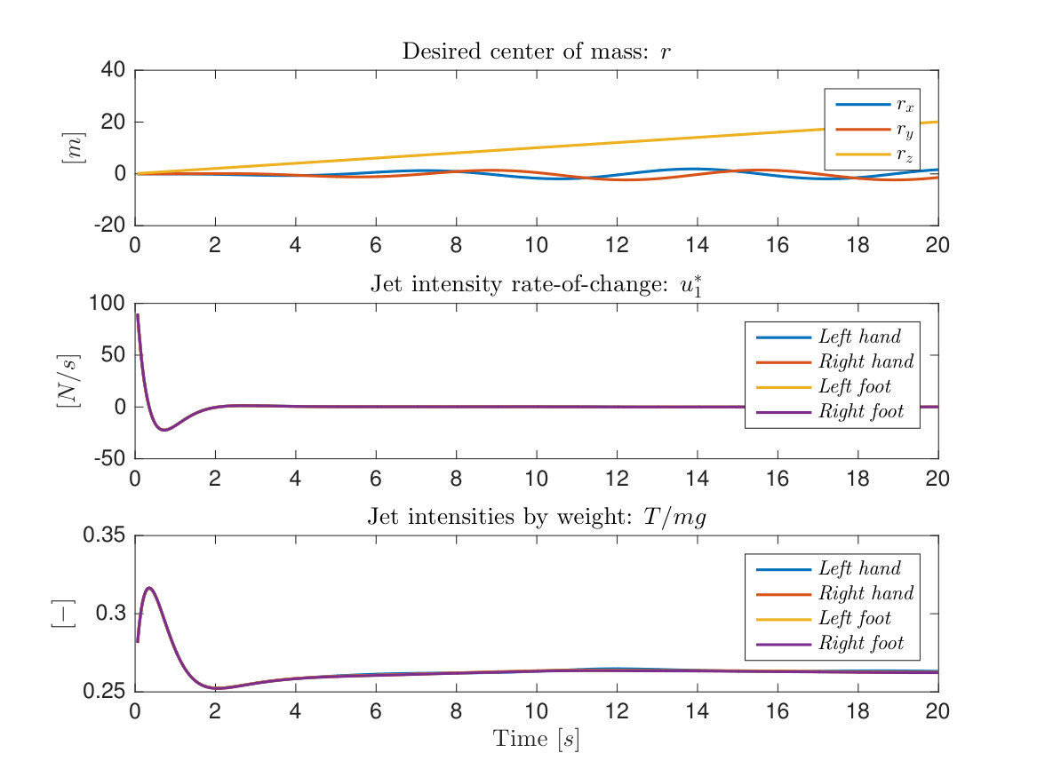 Figure 2
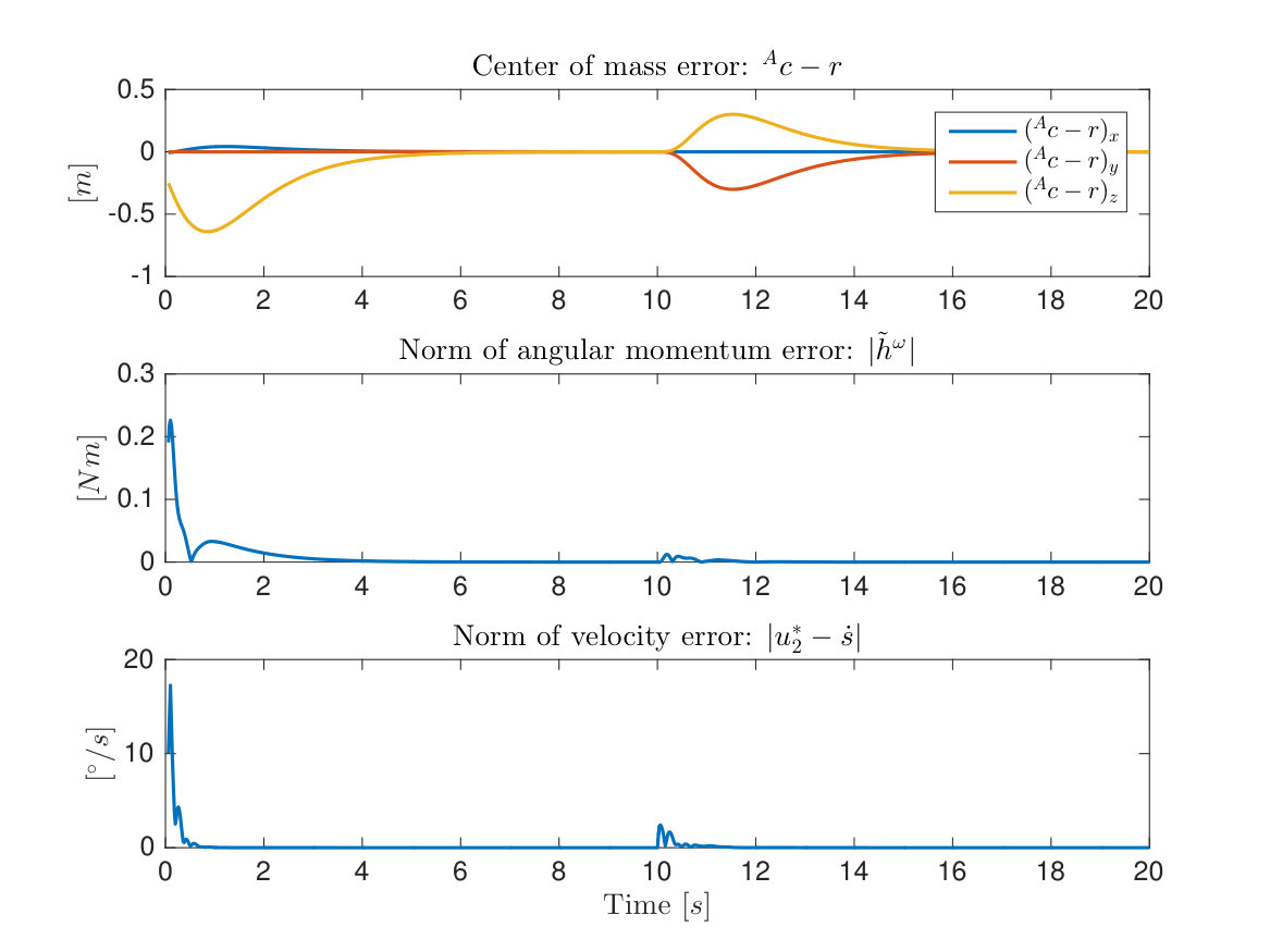 Figure 3
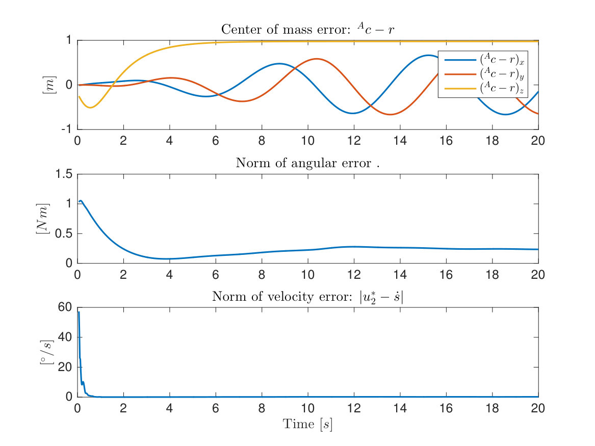 Figure 4
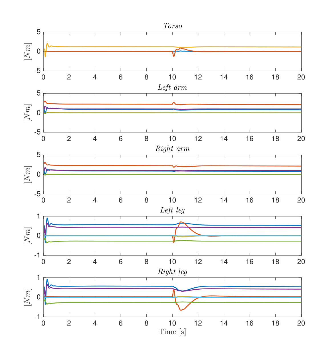 Figure 5
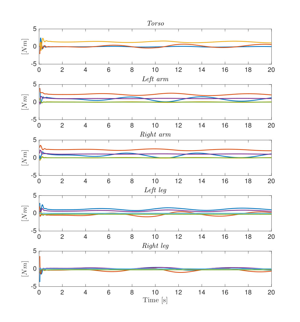 Figure 6
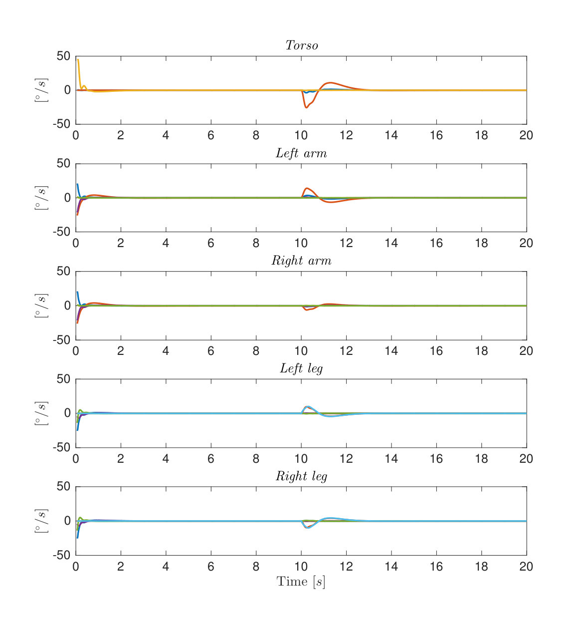 Figure 7
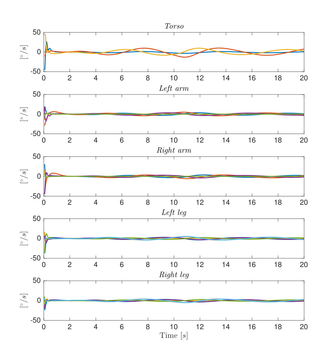 Figure 8
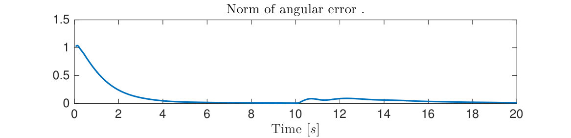 Figure 9
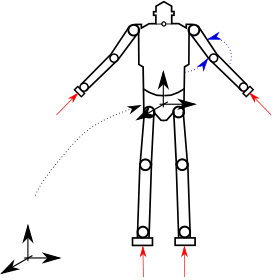 Figure 10
 Figure 11
Peer Reviews
No public reviews on file for this paper yet. If you reviewed it on a platform where reviews are public (OpenReview, ICLR, NeurIPS, ICML), you can paste yours below so the community can read it here.
Videos
No videos yet. Explain this paper in a talk, walkthrough, or lecture? Add one.
Taxonomy
TopicsRobotic Locomotion and Control · Prosthetics and Rehabilitation Robotics · Control and Dynamics of Mobile Robots
Momentum Control of an Underactuated Flying Humanoid Robot
Daniele Pucci, Silvio Traversaro, Francesco Nori *This work was supported by FP7 EU project CoDyCo under Grant 600716 ICT 2011.2.1 Cognitive Systems and Robotics.All authors belong to the iCubFacility Department, Istituto Italiano di Tecnologia, Genoa 163, Italy [email protected]
Abstract
The paper takes the first step towards the development of a control framework for underactuated flying humanoid robots. These robots may thus have the capacities of flight, contact locomotion, and manipulation, and benefit from technologies and methods developed for Whole-Body Control and Aerial Manipulation. As in the case of quadrotors, we assume that the humanoid robot is powered by four thrust forces. For convenience, these forces are placed at the robot hands and feet. The control objective is defined as the asymptotic stabilization of the robot centroidal momentum. This objective allows us to track a desired trajectory for the robot center of mass and keep small errors between a reference orientation and the robot base frame. Stability and convergence of the robot momentum are shown to be in the sense of Lyapunov. Simulations carried out on a model of the humanoid robot iCub verify the soundness of the proposed approach.
I Introduction
The general purpose of providing humanoid robots with some degree of locomotion and manipulation has driven most of the recent research in the humanoid robotics community. Legged and wheeled locomotion, for instance, have proven to be feasible on various humanoid platforms, which can now be envisioned as interfaces for user assistance in several domains (see, e.g., [1, 2]). The robot underactuation combined with the (usually) large number of the robot degrees-of-freedom are among the main difficulties for humanoid robot locomotion and manipulation control. This paper takes the first step towards the development of platforms having the capacities of flight, contact locomotion, and manipulation, and proposes a framework for underactuated flying humanoid robots. Hence, the proposed platforms belong to the domain of interests of both Whole-Body Loco-Manipulation and Aerial Manipulation [3, 4], the union of which may be referred to as Whole-Body Aerial Loco-Manipulation.
Humanoid and flying robot control has developed along different directions, and suffer from specific limitations.
Humanoid robot control is often adddressed assuming the robot attached to ground, and in this case the robot is referred to as fixed-base [5]. To weaken this assumption, one can apply the Euler-Poincarè formalism that provides one with singularity free equations of motion for the humanoid robot [6, Chapter 13]. In this case, the robot is referred to as floating base. When considering these robot equations of motion, however, the mechanical system representing the humanoid robot is underactuated, which forbids full feedback linearization of the underlying system [7]. The system underactuation is usually dealt with by means of constraints arising from the contacts between the robot and the environment. From the control design perspective, instead, a common strategy for humanoid robots is based on the so called stack-of-task [8]. These strategies usually consider several control objectives organized in a hierarchical or weighted prioritization. Often, the high-priority task is the stabilization of the robot momentum [8, 9, 10], whose essence is that of controlling the robot center-of-mass and angular momentum while guaranteeing stable zero-dynamics [11]. Quadratic programming (QP) solvers can be used to monitor contact forces while achiving momentum control [12, 13].
Besides classical flight control [14], small and versatile aircraft – referred to as Vertical Take Off and Landing (VTOL) vehicles – have attracted the nonlinear control community effort of the last decade (see, e.g., [15, 16]). One of the main assumptions of these work is that the flying robot is powered by a body-fixed thrust force, and moves at relatively small velocities. This latter assumption renders the aerodynamic forces negligible when compared to gravity, and drag effects are but seldom taken into account [16]. Then, a common approach for VTOL position control is the so-called vectored-thrust control paradigm: the aircraft angular velocity is considered as a control input, and its main role is to align thrust and gravity forces.
We believe that there is a strong technological benefit in bringing humanoid and flying robots closer: a platform combining these two robot natures may have, at least theoretically, the capacities of flight, contact locomotion, and manipulation, eventually not all used at the same time. A first step in this direction has already been taken by the so-called Aerial Manipulation, which conceives platforms capable to fly and manipulate [4]. Most robots having these two capacities are composed of a VTOL equipped with one or several robotic arms [17, 18]. These robots, however, are not energetically efficient when flying in confined spaces, and an additional capacity of contact locomotion may lower energy consumption considerably. Also, the robot capacity of making contacts with the environment may robustify the achievement of manipulation tasks: an additional end-effector may be used to make a contact with the environment, thus robustifying the overall system against wind gusts.
This paper takes a further step in bringing humanoid and flying robots closer, and proposes a control architecture for flying humanoid robots. We assume that a humanoid robot is powered by four thrust forces installed at the robot end effectors, namely the robot hands and feet. Four turbo engines exemplify the robot actuation assumed in this paper. The control objective is the asymptotic stabilization of the robot centroidal momentum [19], which allows us to stabilize a reference trajectory for the center of mass and keep small, bounded errors between a desired orientation and the robot base frame. Reminiscent of the vectored-thrust control paradigm in VTOL control, we assume that the robot joint velocities can be considered as control input, and we then use them to align the effect of thrust forces with gravity effects. Aerodynamic effects are here neglected, and stability and convergence is shown to be in the sense of Lyapunov. A quadratic programming (QP) solver is employed to consider actuation limits. Finally, the robot joint torques that stabilize the (desired) joint velocities (in turn achieving momentum control) are generated via an high-gain control at the joint level. Simulation results performed on the humanoid robot iCub verify the soundness of the proposed approach.
The paper is structured as follows. Section II introduces notation, equations of motion, and robot actuation. Section III describes the strategy for momentum, center of mass position, and orientation control. Simulations verifying the soundness and robustness of the control laws are presented in Section IV. Remarks and perspectives conclude the paper.
II Background
II-A Notation
- •
denotes an inertial (absolute) frame, composed of a point (origin) and an orientation frame with its axis pointing against the gravity, and the norm of gravitational acceleration. Given two orientation frames and , and vectors of coordinates expressed in these orientation frames, i.e. , respectively, the rotation matrix is such that .
- •
is the identity matrix of size ; is the zero matrix of size and .
- •
is the skew-symmetric matrix such that , with the cross product operator in .
II-B Robot modelling
We assume that the humanoid robot is composed of rigid bodies – called links – connected by joints with one degree of freedom each. The configuration space of the multi-body system can then be characterized by the position and the orientation of a frame attached to a robot link – called base frame – and the joint configurations. More precisely, the robot configuration space is defined by: An element of the set is a triplet , where denotes the origin and orientation of the base frame expressed in the inertial frame, and – which characterizes the robot shape – denotes the joint angles. The velocity of the multi-body system can then be characterized by the set defined by: . An element of is then , where is the linear and angular velocity of the base frame w.r.t. the frame , i.e. .
Applying the Euler-Poincaré formalism [20, Ch. 13.5] to the robot yields the following equations of motion:
[TABLE]
where are the mass and Coriolis matrix, respectively, is the gravity vector, are the internal actuation torques, and is the th of the external forces applied by the environment on robot. In particular, we assume that the application point of the external force is the origin of a frame , which is attached to the robot’s link where the force acts; the external force is expressed in a frame whose orientation coincides with that of the inertial frame . The Jacobian is the map between the robot’s velocity and the linear velocity of the origin of , i.e.
II-C Robot actuation
We assume that the robot is powered by four thrust forces that act along the directions , with , , respectively. The application points of the thrust forces are the origins of four frames attached to the robot end-effectors, e.g., the robot hands and foot. The thrust force directions, instead, move accordingly to the robot end-effectors, since thrust forces are assumed to be attached to the end-effector links. Figure 1 depicts the notation used for the robot actuation. Four turbo engines installed at the robot end-effectors exemplify the actuation assumed for the humanoid robot111 For the humanoid robot iCub, we are considering the turbo engine JETCAT P100 RX [21] (weight: 1050gr; length: 245mm; thrust: 100N @152000 1/min). Note that the weight of iCub is about 30 Kg, which means that four engines suffice for hovering when fuel is kept off board. . We also assume that each thrust force is measurable. This latter assumption holds, for instance, when force sensors are installed in series with the turbo engines.
By defining , the effects of the external thrust forces on the right hand side of the equations of motion (1) can be compactly written as follows:
[TABLE]
III Control Design
III-A Problem statement
In light of section II-C, the equations of motion
[TABLE]
are powered by control inputs. This in turn implies that controlling the entire robot configuration space , which is of dimension222The set is a Lie Group. Hence, the dimension of is the dimension of the algebra associated with it. , may not be straightforward being system (3) underactuated and thus not feedback linearisable. Let us remark that one may attempt at the stabilization of the configuration space by applying advanced techniques developed for underactuated systems evolving on Lie Groups [22, 23]. The application of these techniques, however, is beyond the scope of this paper.
Assume that the control objective is the asymptotic stabilization of a frame – i.e. origin and orientation – associated with a robot link. Without loss of generality, assume that one wants to control the base frame of the humanoid robot. The equations of motion of the base frame are given by:
[TABLE]
with the linear and angular velocity of the base frame, the Jacobian of the base frame, and the robot acceleration obtained from the robot equations of motion (3). More precisely, by using the equations (3), one can evaluate the robot acceleration and substitute it into Eq. (4), thus obtaining an instantaneous relationship between the base acceleration and the control inputs , i.e.
[TABLE]
Then, one may attempt at the control of a reference frame by performing feedback linearisation of the above function with proper feedback correction terms to achieve asymptotic stability. One of the main drawbacks of this approach is that the joint torques have little influence on the base acceleration , which may render the associated control laws ill-posed especially close to constant reference position-and-orientation for the base frame. As a matter of fact, at low joint velocities, a first approximation for the robot equations of motion is given by the Newton-Euler equations, which corresponds to assuming that the robot behaves as a single rigid body. In this case, the dynamics can be obtained from the Newton-Euler equations, which clearly do not depend upon the (internal) joint torques but only on the four (external) thrust forces. Having only four inputs in this dynamics, one cannot perform feedback linearisation of the six-dimensional dynamics .
Now, since the mass matrix is positive definite, and thus invertible, the equations (3) point out that the joint dynamics can be feedback-linearized via a proper choice of the joint torques . So, any differentiable, desired joint velocity can be stabilized with any desired settling time. We then make the following assumption.
Assumption 1**.**
The joint velocity and the thrust forces rate-of-change, i.e. , can be chosen at will and then considered as control inputs.
In the language of Automatic Control, assuming as control variable is a typical backstepping assumption. Then, the production of the joint torques associated with the desired joint velocities can be achieved via classical nonlinear control techniques [24, p. 589] or high-gain control.
III-B Control objective and centroidal momentum dynamics
This section shows that despite the aforementioned underactuation, it is possible to conceive control laws for the Newton-Euler equation of the multibody system without any approximation. Then, the control objective for the reminder of this section is defined as follows:
- •
Asymptotic stabilization of the robot centroidal momentum about desired, smooth values .
When complemented with integral correction terms, the laws for the momentum control allows us to:
stabilize a reference trajectory for the robot center of mass ;
keep small, bounded errors between a reference orientation and the robot base frame.
Note that the choice of the above objective renders the dimension of the control task equal to six. This means that under Assumption 1, we may attempt at achieving this task by means of the control inputs . More precisely, let denote the momentum error defined by
[TABLE]
Then, by recalling that the rate-of-change of the centroidal momentum equals the summation of all external wrenches acting on the robot [25], one has the following dynamics:
[TABLE]
with ,
[TABLE]
Eq. (6a) points out that the dynamics are underactuated even if one assumes that the thrust intensities can be considered as control input, and this renders the control of these dynamics not straightforward.
The equation (6a) highlights also that at the equilibrium configuration , the effect of the thrust intensities must oppose the gravity plus , i.e.
[TABLE]
The above equation is reminiscent of the so-called vectored-thrust control paradigm used in recent flight dynamics control techiniques. In this literature, in fact, the aircraft angular velocity is assumed as control input, and then exploited to align the thrust force against the effect of gravity and, in general, of external forces [16, 15]. This in turn emphasizes the role of the joint velocities in establishing Eq. (11): they are in charge of aligning the total thrust force to the gravity and desired momentum rate-of-change effect.
More precisely and generally, define
[TABLE]
with two symmetric positive definite matrices, and the variable –representing the integral of – governed by . Then, Eqs. (6a) can be rewritten as follows:
[TABLE]
with the matrix given by (8a),
[TABLE]
and the Jacobian matrix mapping the robot velocity into the velocities , i.e. where is the angular velocity associated to the th end-effector frame, i.e. .
III-C Momentum control
In view of the dynamics (14a), the main role of the control inputs is to bring the variable to zero, which means that the effect of the thrust forces must oppose the apparent force (see Eq. (12a)). To introduce the control laws accomplishing this task and stabilizing the desired momentum , let us recall that the centroidal momentum is linear versus the robot velocity . Namely, there exists a Jacobian matrix such that
[TABLE]
with an invertible matrix, and . The matrix is usually referred to as centroidal momentum matrix. We can now present the control laws for system (14a).
Theorem 1**.**
Assume that Assumption 1 holds and define
[TABLE]
with a symmetric positive definite matrix.
If there exist smooth control inputs such that
[TABLE]
*then the closed loop equilibrium point of system (14a) is globally asymptotically stable. *
The proof is given in the Appendix. The main condition of the above theorem is Eq. (24). Let us remark that the number of control inputs to satisfy this condition is , which means that as long as
[TABLE]
one is left with a redundancy of dimension to render Eq. (24) satisfied. This redundancy is later exploited to attempt at the stabilization of the system zero dynamics, i.e. the evolution of system (3) at .
The explicit form of the state feedback laws, namely , is here omitted because the expression (24) is later exploited into the formulation of a quadratic programming problem, which allows us to take into account inequality constraints on the control inputs .
Let us remark that the control laws satisfying Eq. (24) are similar to those obtained by applying pure-feedback linearization techniques with output . In particular, the output is of relative degree equal to three, and one can then apply feedback linearization on the obtained dynamics. The laws deduced with this approach, however, usually forbid to choose control gains independently from each other when the relative degree is higher than two. Also, simulations we have performed tend to show that the law proposed here are more robust w.r.t. to modeling errors than those obtained from pure feedback linearization.
III-D Velocity and position control
The control laws satisfying Eq. (24) can also be used to stabilize a (smooth) desired velocity for the robot center-of-mass. To this purpose, let us recall that the centroidal momentum can be decomposed into a linear and angular component , respectively. Recall also that the linear component is given the robot center-of-mass velocity times its mass . In formule,
[TABLE]
Consequently, the control laws stabilizing a desired velocity for the robot center-of-mass are those satisfying Eq. (24) with the desired momentum defined as follows:
[TABLE]
with the desired angular momentum. Clearly, stability and convergence statements of Theorem 1 are retained under the same assumptions.
Analogously, one can exploit the control laws satisfying Eq. (24) to stabilize a (smooth) desired position for the robot center-of-mass. In particular, it suffices to choose the desired momentum as in Eq. (26) with and to set the integral initial condition such that
[TABLE]
Again, stability and convergence statements of Theorem 1 are retained under the same assumptions.
III-E Orientation control
This section proposes modifications to Eq. (24) for the control of the robot base frame towards desired values . Let us first make a short digression on orientation control on .
The problem of stabilizing a desired orientation for a rigid body orientation may not be straightforward. For instance, it is known that the topology of forbids the design of smooth controllers that globally asymptotically stabilize a reference orientation [26]. Then, quasi-global asymptotic stability is a common feature that orientation controllers guarantee. Just to recall a result:
Lemma 1** ( [27] p. 173).**
Let skew for any matrix , and the operator defined by . Consider the orientation dynamics where is considered as control input. Assume that the control objective is the asymptotic stabilization of a (constant) desired attitude . Then,
[TABLE]
renders the equilibrium point quasi globally stable.
Let us recall that to evaluate the control torques generating the angular velocity (28), the correction terms (28) are first multiplied by the body inertia, and then complemented with additional velocity correction terms [27, p. 178].
The orientation control for the robot base frame proposed in this paper builds upon the above digression, and consists in modifying the term in (24) so as to take into account the orientation correction term (28). More precisely, recall that the robot centroidal angular momentum can be expressed in terms of the total robot inertia as follows, where is the so-called locked angualr velocity [19]: the terminology encompasses the fact that when joint velocities are blocked, , then corresponds to the angular velocity of the humanoid robot, which behaves as a rigid body. This suggests that the control laws (24) with
[TABLE]
can guarantee good tracking performance of the base frame towards the reference orientation . It is important to emphasize that the asymptotic stability of the equilibrium point containing is not guaranteed in this case. Simulations that we have performed, however, tend to show that the suggested control law for the orientation control of the base frame can guarantee good tracking performance even if asymptotic stability is not guaranteed. Control laws ensuring stability properties of the equilibrium point containing will be the subject of forthcoming studies.
III-F Orientation and position control
In light of the above, the control of the robot center-of-mass and base frame can be attempted by using the control laws satisfying Eq. (24) with given by (26), , and
[TABLE]
III-G Zero dynamics and optimization problem
Now, assume that the humanoid robot center of mass and base frame are stabilized about the reference position and orientation, respectively. This constrains only six out of the degrees of freedom of the robot, thus leaving an -dimensional * free-motion* of the system at the desired values: this free motion should be at least bounded. More precisely, this section discusses how to deal with the boundedness of the system zero dynamics by exploiting the input redundancy when satisfying Eq. (24).
Let us recall that stability and convergence in Theorem 1 are shown when Eq. (24) holds, i.e. . Finding the control inputs such that this equation holds in general leaves a dimensional input redundancy, which can be used for other purposes. We here use this redundancy so as the joint velocity are as close as possible to a postural task of the following form:
[TABLE]
with a symmetric positive definite matrix, and a reference position for the joint configuration. If the joint configurations tend to the reference value , thus reducing the risk of unstable zero dynamics.
We combine the tasks of satisfying Eq. (24) and in a weighted optimization problem of the following form:
[TABLE]
where are positive weighting constants, and and are the lower and upper bounds for the thrust-intensity variations and joint velocities , respectively. Note that the cost function of the optimization problem (32a) contains also some regularization terms depending on and .
III-H Torque control for joint velocity stabilisation
The solution to the problem (32a) is a pair , namely the instantaneous rate-of-change of the thrust intensities and the joint velocities . This latter value is then interpreted as a desired value to be stabilized by a torque-control law. More precisely, the route we follow is high-gain control for the stabilization of . Now, partition (3) as follows with , , , with and . Then, from Eq. (3), one gets
[TABLE]
In view of Eq. (34a), the stabilization of a desired joint velocity is then attempted by means of the following high-gain torque control law:
[TABLE]
IV Simulation Results
This section presents simulations results obtained by applying the control algorithm discussed in the previous section. These simulations have been carried out by using the humanoid robot iCub with 25 DoFs [28]. In particular, the robot joint angles can be partitioned into five robot parts, which correspond to the robot torso , left arm , right arm , left leg , and right leg , i.e. .
IV-A Simulation environment and control parameters
The custom simulation environment is in charge of integrating the equations of motion (3) with the joint torques given by (36) and the thrust intensities provided by the time integration of , which are in turn generated by (32a).
For time-integration purposes of (3), we parametrize by means of a quaternion representation . The resulting state space system, which is integrated through time, is then: , and its derivative is given by The constraints are enforced during the integration phase [29]. The system evolution is obtained by integrating the constrained dynamical system with the numerical integrator MATLAB ode15s thanks to our software abstraction interfaces – described in [30] – which provide us the elements of the equations of motion (36), e.g. the mass matrix.
The humanoid robot initial condition is , which corresponds to having the robot arms open ( on the robot shoulders) and the base frame corresponding to the inertial frame. The robot legs are at the zero position, which corresponds to having the robot legs straight.
We then set the control gains as follows: for the momentum control described in Theorem 1, , , ; for the optimization problem (32a): , , , , , with limits , ; and for the high-gain torque control (36): , .
In the following simulations, noise is not considered. The main reason why is that given the robot actuation, we expect that the noise produced by turbo engines may be higher than that produced by the robot joint motors. Noise nature and amplitude produced by turbo engines when attached to the humanoid robot is not known for the time being. Hence, noise will be considered after proper experimental campaigns will be carried on to identify noise nature and amplitude.
IV-B *Simulation 1: piece-wise constant velocity trajectory without
orientation control*
The first simulation concerns the stabilization of a reference trajectory obtained by integrating the following piece-wise constant reference velocity:
[TABLE]
with . To stabilize the resulting trajectory, we then apply the algorithm (32a)-(36), with the integral term given by (27) and . Data associated with this simulation are depicted in Figures 2–4. In particular, from top to bottom, Figure 2 depicts the tracking error of the robot center of mass, the angular momentum error, and the norm of the joint velocity error . Since all tracking errors converge to zero, the simulation results shown in Figure 2 verify the statements of Theorem 1 when combined with the high-gain control (36). The control gains and influence the settling time with which both tracking errors of the center-of-mass and the angular momentum tend to zero. Still in Figure 2, observe also that the norm of the velocity error tends to zero meaning that the high-gain control (36) for joint velocity stabilization is working properly. The joint torques (36) to obtain this stabilization are depicted in Figure 3. Observe that despite the high-gain control chosen in this paper, the joint torques remain relatively small during the task .
The outcome of the optimization problem (32a) is depicted in Figures 4. Note how the optimizer tends to choose solutions that render equal all thrust intensities variations thanks to the term . The smaller this regularization term, the more different the rate-of-change of the jet intensities.
IV-C Simulation 2: helicoidal flight with orientation control and non-perfect control model to test controller robustness
The second simulation consists in tracking the reference trajectory given by
[TABLE]
with
[TABLE]
After , it represents a helicoidal trajectory of radius with vertical speed of . Differently to the previous section, we here test the trajectory tracking controller with orientation control. So, we apply (32a)-(36) with the integral term given by (30) and obtained by rotating about the vertical axis of . Then, the robot is expected to rotate about the vertical axis to reduce the orientation error. Also, to test the control robustness, the controller has been calculated with estimated parameters that differ from the real ones of . More precisely, the controller is evaluated by over-estimating the real model, i.e. , , and . As depicted in Figure 5, modeling errors lead to non convergence of the center-of-mass tracking error and orientation error to zero. However, relatively small bounded errors between actual and reference signals are kept, despite the controller (32a)-(36) (30) is not guaranteed to possess stability and convergence properties. This shows a degree of robustness versus modeling errors of the control laws presented in this paper. Let us remark that the orientation control performance degrades quickly for a time-varying reference orientation, and this calls for studies and extensions of the control laws presented in this paper for time-varying orientation tracking. Due to lack of space, plots depicting the control inputs are omitted.
V Conclusions
This paper has proposed extensions of the so-called vectored-thrust control paradigm used in VTOL control to the case of an underactuated flying humanoid robot. The main assumption is that the humanoid robot is powered by four thrust forces placed at the robot end effectors: these forces reduce but do not eliminate the well-known humanoid robot underactuation. Within this actuation framework, we have presented control laws guaranteeing stability and convergence properties for the robot centroidal momentum. Slight modifications to these laws allows us to track a desired reference trajectory for the center of mass and keep small tracking errors between a reference orientation and the robot base frame.
In this respect, future work consists in proposing control laws guaranteeing stability and convergence not only for the desired center of mass position and angular momentum, but also for the reference orientation of the base frame. Also, the model of the external forces acting on the robot neglects the aerodynamic phenomena. Hence, future work will also consist in extending vectored-thrust control paradigm with aerodynamic effects to the case of the considered flying humanoid [31, 32, 33].
Appendix: proof of Theorem 1
Consider the following Lyapunov function candidate
[TABLE]
Note that . Direct calculations show along the trajectories of system (14a) is given by:
[TABLE]
Now, it is clear that if the term in the parenthesis on the right hand side of the above equation is equal to . In view of (15a) and (12a), imposing yields:
[TABLE]
By substituting and in (42), one gets the condition (24) of Theorem 1. As a consequence, if (24) – and consequently (42) – are always satisfied, then in Eq. (41) becomes And implies the stability of the equilibrium point and also global boundedness of the system trajectories.
Now, as long as (42) is satisfied, the closed loop dynamics is given by and (14a) (15a): therefore, the closed loop dynamics is autonomous, and we can use LaSalle Theorem to conclude that . This implies that , , and , . By using these implications with (15a), namely one obtains that . Hence, the equilibrium point is asymptotically stable. Global asymptotic stability comes from radial unboundedness of .
The reference list from the paper itself. Each links out to its DOI / PubMed record.
- 1[1] M. Simon, “Boston Dynamics’ New Rolling, Leaping Robot Is an Evolutionary Marvel,” Wired , 2017. [Online]. Available: https://www.wired.com/2017/03/boston-dynamics-new-rolling-leaping-robot-evolutionary-marvel/
- 2[2] P.-B. Wieber, R. Tedrake, and S. Kuindersma, Modeling and Control of Legged Robots . Cham: Springer International Publishing, 2016, pp. 1203–1234.
- 3[3] E. Farnioli, M. Gabiccini, and A. Bicchi, “Toward whole-body loco-manipulation: Experimental results on multi-contact interaction with the walk-man robot,” in 2016 IEEE/RSJ International Conference on Intelligent Robots and Systems (IROS) , Oct 2016, pp. 1372–1379.
- 4[4] K. Kondak, A. Ollero, I. Maza, K. Krieger, A. Albu-Schaeffer, M. Schwarzbach, and M. Laiacker, “Unmanned aerial systems physically interacting with the environment: Load transportation, deployment, and aerial manipulation,” in Handbook of Unmanned Aerial Vehicles . Springer, 2015, pp. 2755–2785.
- 5[5] R. Featherstone, Rigid Body Dynamics Algorithms . Secaucus, NJ, USA: Springer-Verlag New York, Inc., 2007.
- 6[6] J. E. Marsden and T. Ratiu, Introduction to mechanics and symmetry: a basic exposition of classical mechanical systems . Springer Science & Business Media, 2013, vol. 17.
- 7[7] J. A. Acosta and M. Lopez-Martinez, “Constructive feedback linearization of underactuated mechanical systems with 2-DOF,” Decision and Control, 2005 and 2005 European Control Conference. CDC-ECC ’05. 44th IEEE Conference on , 2005.
- 8[8] B. Stephens and C. Atkeson, “Dynamic balance force control for compliant humanoid robots,” in Intelligent Robots and Systems (IROS), 2010 IEEE/RSJ International Conference on , 2010, pp. 1248–1255.