Spin Pumping and Inverse Spin Hall Voltages from Dynamical Antiferromagnets
{\O}yvind Johansen, Arne Brataas

TL;DR
This paper investigates spin pumping and inverse spin Hall voltages in dynamical antiferromagnets, demonstrating field-dependent voltage enhancements near spin-flop transitions in certain insulating antiferromagnets.
Contribution
It provides a theoretical analysis of spin pumping and inverse spin Hall voltages in antiferromagnets, highlighting the effects of magnetic fields and anisotropy on voltage signals.
Findings
Significant voltage enhancement near spin-flop in MnF2 and FeF2.
Weaker voltages and no enhancement in NiO.
Field tuning can optimize spin pumping signals.
Abstract
Dynamical antiferromagnets pump spins efficiently into adjacent conductors as ferromagnets. The high antiferromagnetic resonance frequencies represent a challenge for experimental detection, but magnetic fields can reduce these resonance frequencies. We compute the inverse spin Hall voltages resulting from dynamical spin excitations as a function of a magnetic field along the easy axis and the polarization of the driving AC magnetic field perpendicular to the easy axis. We consider the insulating antiferromagnets MnF, FeF, and NiO. Near the spin-flop transition, there is a significant enhancement of the DC spin pumping and inverse spin Hall voltage for the uniaxial antiferromagnets MnF and FeF. In the biaxial NiO, the voltages are much weaker, and there is no spin-flop enhancement of the DC component.
Click any figure to enlarge with its caption.
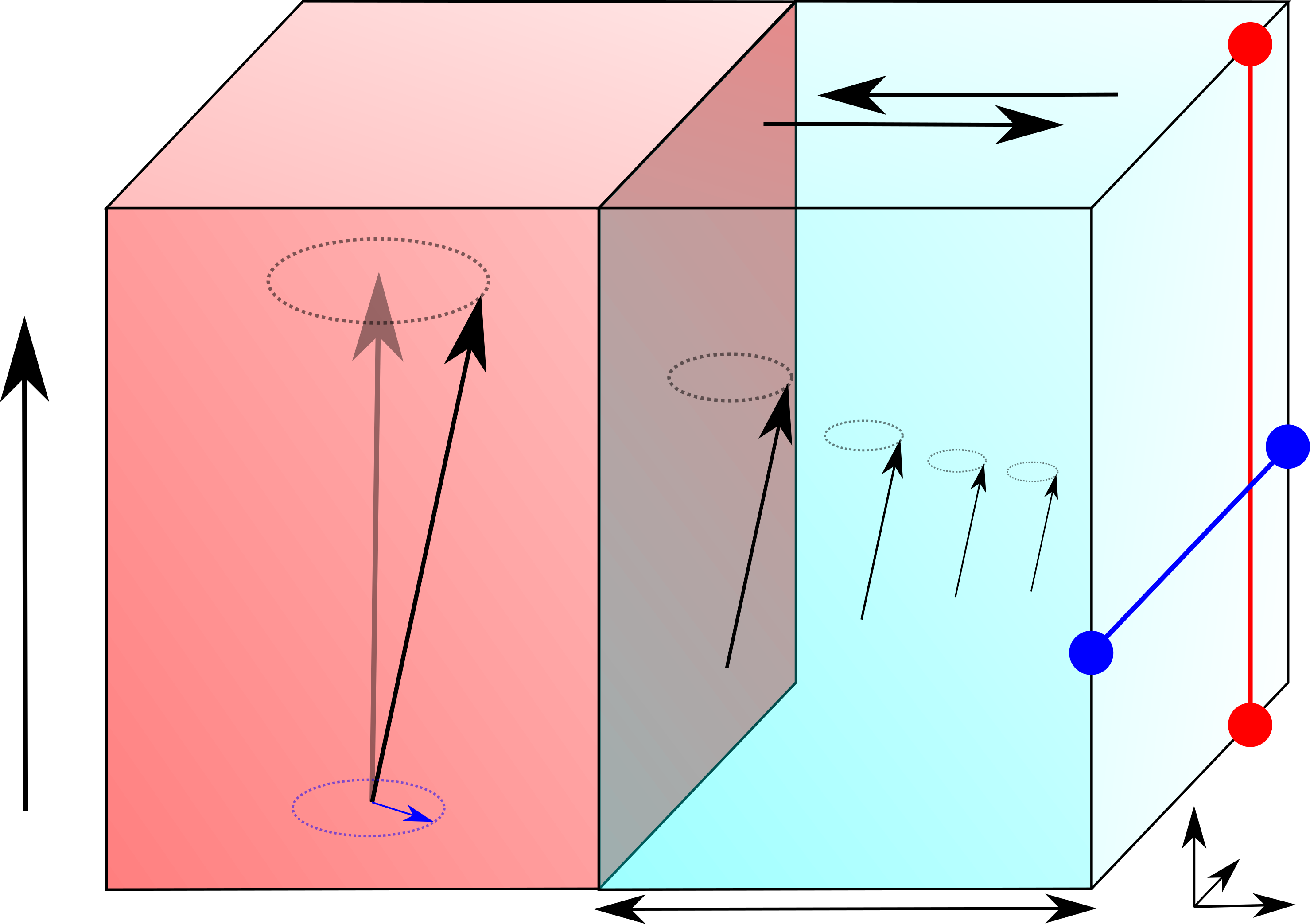 Figure 1
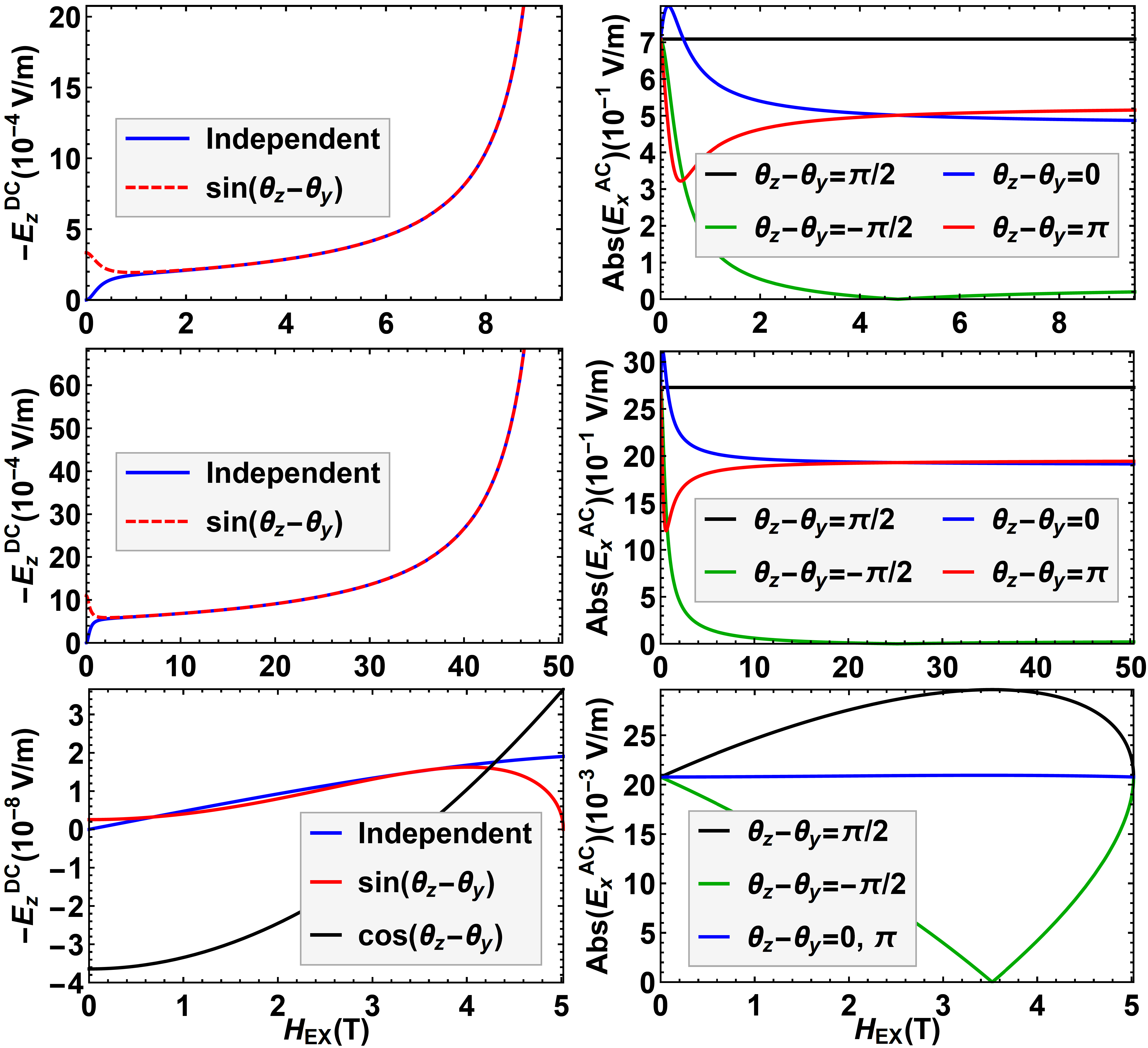 Figure 2
 Figure 3
Peer Reviews
No public reviews on file for this paper yet. If you reviewed it on a platform where reviews are public (OpenReview, ICLR, NeurIPS, ICML), you can paste yours below so the community can read it here.
Videos
No videos yet. Explain this paper in a talk, walkthrough, or lecture? Add one.
Spin Pumping and Inverse Spin Hall Voltages from Dynamical Antiferromagnets
Øyvind Johansen
Arne Brataas
Department of Physics, Norwegian University of Science and Technology, NO-7491, Trondheim, Norway
Abstract
Dynamical antiferromagnets pump spins efficiently into adjacent conductors as ferromagnets. The high antiferromagnetic resonance frequencies represent a challenge for experimental detection, but magnetic fields can reduce these resonance frequencies. We compute the inverse spin Hall voltages resulting from dynamical spin excitations as a function of a magnetic field along the easy axis and the polarization of the driving AC magnetic field perpendicular to the easy axis. We consider the insulating antiferromagnets MnF2, FeF2, and NiO. Near the spin-flop transition, there is a significant enhancement of the DC spin pumping and inverse spin Hall voltage for the uniaxial antiferromagnets MnF2 and FeF2. In the biaxial NiO, the voltages are much weaker, and there is no spin-flop enhancement of the DC component.
Spin pumping is a versatile tool for probing spin dynamics in ferromagnets Mizukami et al. (2001); Urban et al. (2001); Tserkovnyak et al. (2002); Brataas et al. (2002); Heinrich et al. (2003); Tserkovnyak et al. (2005). The magnitude of the pumped spin currents reveals information about the magnetization dynamics and the electron-magnon coupling at interfaces Costache et al. (2006); Heinrich et al. (2011); Kapelrud and Brataas (2013). The precessing spins generate a pure spin flow into adjacent conductors. Inside the conductor, the resulting spin accumulation and currents give insight into the spin-orbit coupling. The inverse spin Hall effect (ISHE) is often used to convert the pure spin current into a charge current, which is detected Mosendz et al. ; Jiao and Bauer (2013). Additionally, the induced non-equilibrium spins can be probed with XMCD measurements Marcham et al. (2013); Baker et al. (2016)
Antiferromagnets (AFs) differ strikingly from ferromagnets Jungwirth et al. (2016). There are no stray fields in antiferromagnets, making them more robust against the influence of external magnetic fields. The recent discovery of anisotropic magnetoresistance Park et al. (2011); Martí et al. (2012); Wang et al. (2014), spin-orbit torques Železný et al. (2014), and electrical switching of an antiferromagnet Wadley et al. (2016) demonstrate the feasibility of antiferromagnets as active spintronics components.
The real benefit of antiferromagnets is that they can enable Terahertz circuits. Unlike ferromagnets, the resonance frequency of antiferromagnets is also governed by the tremendous exchange energy. We recently demonstrated that the transverse spin conductance controlling spin pumping is as large in antiferromagnet-normal metal junctions (AFN) as in ferromagnet-normal metal junctions Cheng et al. (2014). Furthermore, this result is valid even when the magnetic system is insulating. The firm electron-magnon coupling at the interface opens the door for electrical probing of the ultra-fast spin dynamics in antiferromagnets Cheng et al. (2014, 2016).
Precessing spins in antiferromagnets generate Terahertz currents in adjacent conductors. This ability opens new territory in high-frequency spintronics. Such studies could become influential in gathering vital insight into fast electron dynamics and eventually for a broad range of applications. These electric signals also provide further knowledge about the less explored field of antiferromagnetic spin dynamics. This potential requires thorough exploration; we need to establish several critical aspects.
The manner in which spin pumping generates AC and DC inverse spin Hall voltages has yet to be studied in detail. Furthermore, there is a large variety of antiferromagnets and external field configurations that require knowledge beyond the first predictions of the magnitude of the pumped spin current of Ref. Cheng et al., 2014. Recently, researchers explored spin transport through, e.g., the insulating antiferromagnets NiO and MnF2. Unlike the treatment of Ref. Cheng et al., 2014, in NiO, there are two significant anisotropies to consider. As a starting point in the exploration of high-frequency spintronics, it is also important to tune the resonance frequencies to a lower Gigahertz range for easier detection by conventional electronics. The application of an external magnetic field can lower the resonance frequency. However, the details of the magnetic field and its AC component polarization dependence also remain to be classified, a task that we will perform here.
In this Letter, we compute the inverse spin Hall AC and DC voltages generated by spin pumping. We hope that our studies will further motivate these voltages to be experimentally measured. Such studies will provide a needed deeper insight into antiferromagnetic resonance phenomena, features much less explored than their ferromagnetic counterparts in recent decades.
We consider an insulating antiferromagnet-normal metal bi-layer, as illustrated in Fig. 1. We also consider a variety of magnetic anisotropies and magnetic field configurations and strengths. Therefore, the results apply to more complex systems such as biaxial antiferromagnets with elliptical precessional modes. The model also accounts for spin backflow due to the spin accumulation in the metal. We also study how the inverse spin Hall voltages depend on the polarization of the AC magnetic field for different systems, which we find to have a strong influence on the resulting signal. Our main findings are that, when applying an external magnetic field along the easy axis close to the spin-flop transition, we can decrease the resonance frequency while simultaneously significantly increasing the inverse spin Hall signal. The increase in the signal can even overcome the previously anticipated limiting factor in antiferromagnet spin pumping: the ratio of the anisotropic energy to the exchange energy Cheng et al. (2014).
We consider a small antiferromagnet in the macrospin limit whereby all spin excitations are homogeneous. The antiferromagnet has two sublattices, with temporal magnetizations and . The dynamics are described by the staggered magnetizations and the magnetization . These fields satisfy the constraints and . At equilibrium, the sublattice magnetizations are anti-parallel. An AC magnetic field, with a general polarization, drives the magnetic moments at resonance.
The antiferromagnets that we consider are described by the free energy
[TABLE]
where is the gyromagnetic ratio, is the volume of the antiferromagnet, is the exchange frequency, and and are the hard axis (-axis) and easy axis (-axis) anisotropy frequencies. The frequency quantifies the influence of the external magnetic field along the easy axis, whereas and quantify the influence of the AC magnetic field in the -plane. In Table 1, we list the exchange and anisotropy frequencies for MnF2, FeF2 and NiO.
The dynamic Landau-Lifshitz-Gilbert equations that describe the precession of and are
[TABLE]
with the effective fields and . The dissipation and spin-pumping torques are
[TABLE]
where the total Gilbert damping coefficient is a sum of the intrinsic damping and the spin-pumping-enhanced damping: Hals et al. (2011); Cheng et al. (2014).
A linear response expansion around the equilibrium values of and determines the antiferromagnetic resonance (AFMR) frequencies. For simplicity, we only present the resonance frequencies in the exchange limit . This limit is valid for many antiferromagnets but not for FeF2 due to a large anisotropy. In our numerical calculations below, we do not make this approximation. In the exchange limit, the four resonance frequencies below spin-flop are Yosida (1952)
[TABLE]
where . The critical field strength at which the spin-flop transition occurs is in both uniaxial and biaxial antiferromagnets. We will only consider magnetic fields below this value.
Herein, we focus on the right-handed low-energy mode since we want to decrease the resonance frequency. In the absence of an external magnetic field, the resonance frequency of this mode is 0.27 THz for MnF2, 1.41 THz for FeF2, and 0.14 THz for NiO. By applying a magnetic field close to the spin-flop transition, we can reduce these resonance frequencies down to the GHz range. Such a reduction should enable detection of AFMR and the resulting significant spin-pumping-induced AC and DC ISHE voltages.
The pumped spin current from a dynamical antiferromagnet into a normal metal is (Cheng et al., 2014)
[TABLE]
where is the transverse (”mixing”) conductance. The spin pumping from the antiferromagnetic insulator causes a spin accumulation in the normal metal, which in turn produces a spin backflow current Jiao and Bauer (2013). In antiferromagnetic insulators, the backflow spin currents within the sublattices add constructively Gomonay and Loktev (2010); Cheng et al. (2014):
[TABLE]
where is the spin accumulation in the normal metal.
The most significant contributions to the spin current are second order in the deviations from equilibrium along the easy axis and first order along the perpendicular directions. Nevertheless, the leading-order terms in the total spin current only depend on the first-order deviations of the magnetic moments from their equilibrium values, and . It is therefore sufficient to consider the linear response expansions
[TABLE]
where the transverse deviations are and . is the driving frequency of the AC magnetic field. Consequently, to leading order, we can disregard the dependence of the spin backflow on .
The spin accumulation is a solution of the spin diffusion equation
[TABLE]
where the terms on the right-hand side of Eq. (8) are properties of the normal metal such as the diffusion coefficient , the gyromagnetic ratio , and the spin-flip relaxation time , and is the external magnetic field. The boundary conditions for require that the spin current vanishes at the outer edge of the normal metal () and that the current is continuous across the antiferromagnet-normal metal interface (). The diffusion equation can be solved in position-frequency space Jiao and Bauer (2013); Johnson and Silsbee (1988) in terms of the Fourier components of the total spin current at .
The spin current in the normal metal causes a charge current perpendicular to the spin current’s direction and polarization through the ISHE. This charge current is given by Saitoh et al. (2006); Mosendz et al. (2010)
[TABLE]
where is the spin Hall angle in the normal metal and is the area of the AFN interface. Since the system is an open circuit, the charge current accumulates charges at the interfaces. In turn, a generated electric field ensures that the net charge current through the metal vanishes. To determine this electric field, we integrate the charge current over the metallic system to find the electric field needed to cancel the charge current. See the Supplementary Material Sup for the full derivation. The DC component of this electric field becomes
[TABLE]
the first harmonic AC component is
[TABLE]
and the second harmonic AC component is
[TABLE]
Here, we have introduced the conversion coefficient , where is the conductivity of the normal metal. The factors are the -th Fourier components of the spin accumulation at the AFN interface (). We compute that they are
[TABLE]
for the first and second harmonic AC components, and
[TABLE]
for the DC component. All other components of the spin accumulation vanish. The components of the spin accumulation of Eqs. (13) and (14) are expressed in terms of the functions
[TABLE]
with . Here, we have defined , , the spin diffusion length and the one-spin density of state . Note that and consequently vanish in the absence of a magnetic field () and when the precession of the staggered magnetization is circular ().
We will now use our model to compute the ISHE signal as a function of external magnetic fields in an AFPt bilayer. By inserting the linear response ansatz of Eq. (7) into the LLG equations in Eq. (2), we determine the functions and . The components of the AC magnetic field that drives these perturbations are given by for . The phase difference determines the polarization of the AC field, and significantly affects the resulting spin current. In our calculations, we let .
As the material properties of Pt, we use ps Jiao and Bauer (2013), Papaconstantopoulos (1986), Liu et al. (2011), nm, and Meyer et al. (2014). These properties are at 10 K. The transverse conductance has yet to be determined experimentally for antiferromagnets. However, it should be of the same order of magnitude as that of a ferromagnetic or ferrimagnetic material Cheng et al. (2014). A reasonable estimate of this parameter is therefore m*-2* Yoshino et al. (2011); Haertinger et al. (2015), which we use in the following. Experimental measurements of are needed and are further motivated by the present calculations.
The magnitude of the ISHE signal depends on the thickness of the Pt layer. It increases approximately linearly with for and is inversely proportional to for . This qualitative behavior is similar to that in ferromagnetic/normal metal bilayers, cf. Fig. 3(a) in Ref. Jiao and Bauer, 2013. The peak of the ISHE signal is at some value , and for our choice of parameters, it peaks at nm. We use this thickness of the Pt layer for the remaining calculations. The optimal thickness weakly depends on the value of and should therefore be determined experimentally.
Fig. 2 plots the DC and the first harmonic AC components of the ISHE electric field as a function of the magnetic field. In the uniaxial antiferromagnets, MnF2 and FeF2, one contribution to the DC signal is independent of the AC magnetic field polarization, and the other contribution is proportional to . At high magnetic fields, these contributions are equal in magnitude but add constructively or destructively, depending on the circular polarization of the AC magnetic field.
Ref. Cheng et al., 2014 demonstrated that the pumped DC spin current in uniaxial antiferromagnets at resonance is suppressed by the factor . Since is significantly larger in FeF2 (0.61) than in MnF2 (0.13), it was believed that FeF2 gives a stronger signal than does MnF2. However, with our present additional insight, we reach the opposite conclusion at finite magnetic fields. We find that when , the DC signal diverges as . The utilization of the divergence is a better route toward enhancing the ISHE signal than increasing . This implies that MnF2 is a more promising candidate than FeF2 because the spin-flop field of MnF2 (9.5 T) is easier to achieve experimentally than is that of FeF2 (50.4 T).
Unlike the DC component, the first harmonic AC component is independent of the AC magnetic field polarization in the absence of a uniform external magnetic field and converges toward a finite value as . The signal when the polarization is circular () gives the largest DC signal (and AC signal for sufficiently large magnetic fields). Furthermore, this curve becomes independent of the magnetic field. The origin of this is a complicated compensation between the diverging contributions from the out-of-equilibrium fields and the vanishing resonance frequency around the spin-flop transition.
In NiO, the dominant AC magnetic field contribution is linear in the polarization, which is proportional to . Such a feature appears when there is a hard axis, and the precession is in the easy plane. The linear contribution dominates when . In biaxial antiferromagnets, we find that the pumped current is governed by the scaling factor instead of . In discussing the strength of the spin-pumping signals, we should also note that, in both uniaxial and easy-plane antiferromagnets, the signal is inversely proportional to . Since and since is exceptionally large in NiO, the DC spin pumping signal is weak in comparison to that of MnF2 and FeF2. In addition, the DC signal in NiO does not exhibit a divergence as . The first harmonic AC component in NiO is independent of the polarization of the AC magnetic field at the spin-flop transition, unlike the uniaxial antiferromagnets, but the magnitude is small. We do not present the second harmonic AC voltage since it is minimal (and in many cases identically zero) compared to the other voltages. The exception is for NiO just around spin flop, where it can be the same order of magnitude as the DC voltage; however, this is still a very weak signal. Our results imply that uniaxial antiferromagnets are preferred candidates for the observation of spin pumping compared to hard-axis antiferromagnets such as NiO.
Ref. Ross, 2013 conducted preliminary spin-pumping experiments for a MnFPt system. However, they attributed the dominant DC signal to microwave rectification and not spin pumping. Nevertheless, they observed a small change in the signal upon reversal of the magnetic field, which is consistent with spin pumping.
We propose a different experimental geometry to enhance the spin-pumping signal. The use of the AC magnetic field in a plane perpendicular to the easy axis and a polarization increases the DC ISHE signal by a factor of 4. Additionally, by reducing the thickness of the Pt layer from 7 nm to the thickness where the ISHE signal attains its maximum (in our calculations, this is 1.2 nm), we can further amplify the signal by a factor of 2. Together, these improvements will increase the signal strength by an order of magnitude. Whether the signal is due to spin pumping can then easily be tested by the dependence on the polarization of the AC magnetic field according to our model. A circular polarization with doubles the signal strength compared to a linear polarization. On the other hand, a circular polarization with results in no DC spin pumping. In contrast, microwave rectification effects should be much less sensitive to the polarization.
In summary, we computed the inverse spin Hall signal as a result of spin pumping and spin backflow in an AFN bi-layer. Our results apply to any polarization of the AC magnetic field and precessional motion of the magnetizations, and the results can also be used in more complex biaxial antiferromagnets. We demonstrate that the DC signal increases substantially near the spin-flop transition in uniaxial antiferromagnets. Furthermore, the signal strongly depends on the polarization of the AC magnetic field. We also suggest an improved experimental geometry that considerably enhances the DC signal resulting from spin pumping.
The research leading to these results has received funding from the European Research Council via Advanced Grant number 669442 “Insulatronics”, EU FET “Transpire” via grant no. 737038 and The Research Council of Norway via grant no. 239926/F20.
The reference list from the paper itself. Each links out to its DOI / PubMed record.
- 1Mizukami et al. (2001) S. Mizukami, Y. Ando, and T. Miazaki, Jpn. J. Appl. Phys. 40 , 580 (2001).
- 2Urban et al. (2001) R. Urban, G. Woltersdorf, and B. Heinrich, Phys. Rev. Lett. 87 , 217204 (2001) .
- 3Tserkovnyak et al. (2002) Y. Tserkovnyak, A. Brataas, and G. Bauer, Phys. Rev. Lett. 88 (2002).
- 4Brataas et al. (2002) A. Brataas, Y. Tserkovnyak, G. E. W. Bauer, and B. I. Halperin, Phys. Rev. B 66 , 060404 (2002) .
- 5Heinrich et al. (2003) B. Heinrich, Y. Tserkovnyak, G. Woltersdorf, A. Brataas, R. Urban, and G. Bauer, Phys. Rev. Lett. 90 (2003).
- 6Tserkovnyak et al. (2005) Y. Tserkovnyak, A. Brataas, G. E. W. Bauer, and B. I. Halperin, Rev. Mod. Phys. 77 , 1375 (2005) . · doi ↗
- 7Costache et al. (2006) M. V. Costache, M. Sladkov, S. M. Watts, C. H. van der Wal, and B. J. van Wees, Phys. Rev. Lett. 97 , 216603 (2006) .
- 8Heinrich et al. (2011) B. Heinrich, C. Burrowes, E. Montoya, B. Kardasz, E. Girt, Y.-Y. Song, Y. Sun, and M. Wu, Phys. Rev. Lett. 107 , 066604 (2011) .