Necking after extensional filament stretching of complex fluids and soft solids
David M. Hoyle, Suzanne M. Fielding

TL;DR
This paper develops analytical criteria for necking in complex fluids and soft solids during stress relaxation after extensional strain ramps, validated by simulations across various models, revealing delayed necking phenomena.
Contribution
It introduces new analytical criteria for necking during stress relaxation in complex fluids, validated by simulations, and connects delayed necking to similar phenomena in shear banding.
Findings
Two modes of necking identified: stress relaxation curvature and elastic force derivative.
Criteria agree with simulations of Oldroyd B, Giesekus, and RoliePoly models.
Delayed necking occurs after high strain ramps exceeding ~0.7, at certain ramp rates.
Abstract
We perform linear stability analysis and nonlinear slender filament simulations of extensional necking in complex fluids and soft solids, during the stress relaxation process following an interrupted strain ramp. We start by deriving analytical criteria for necking within a highly simplified and generalised scalar constitutive model. Here, we find two different possible modes of necking: one associated with an upward curvature in the stress relaxation function on a log-linear plot, and another related to a carefully defined `elastic' derivative of the tensile force with respect to an imagined sudden strain increment. We showed these two criteria to agree fully with simulations of the Oldroyd B and Giesekus models of polymeric solutions, and with the RoliePoly model of more concentrated polymeric solutions and melts, without polymer chain stretch. With chain stretch included, we find a…
Click any figure to enlarge with its caption.
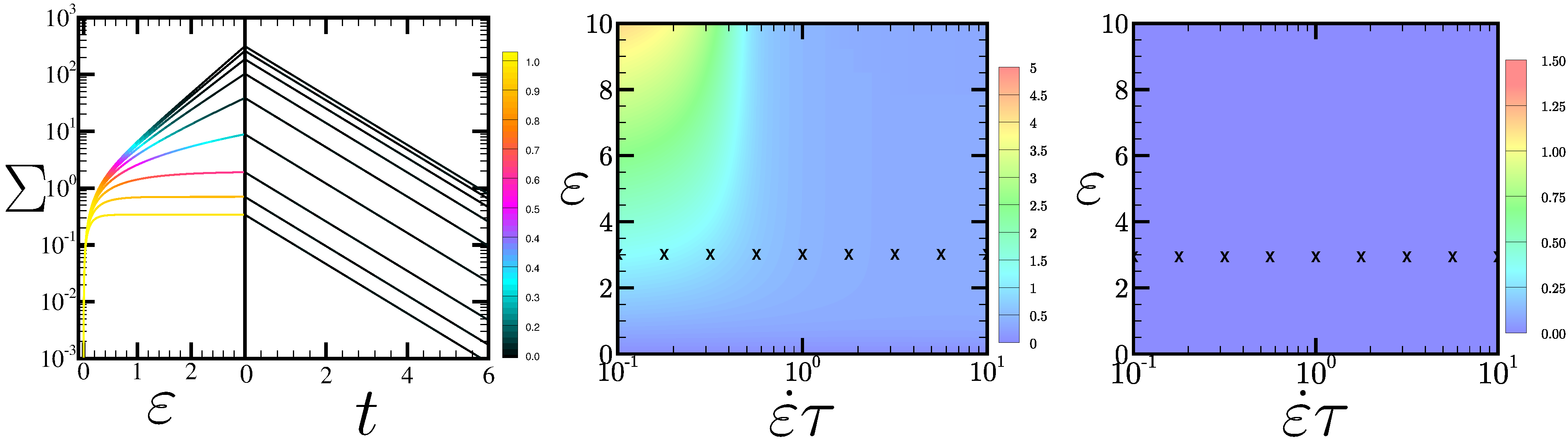 Figure 1
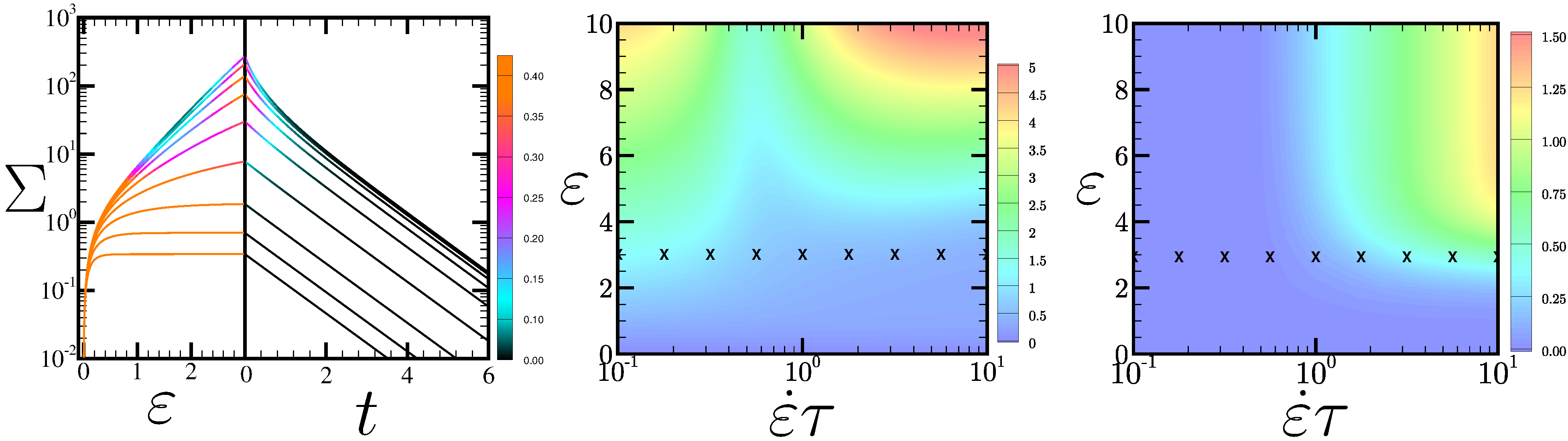 Figure 2
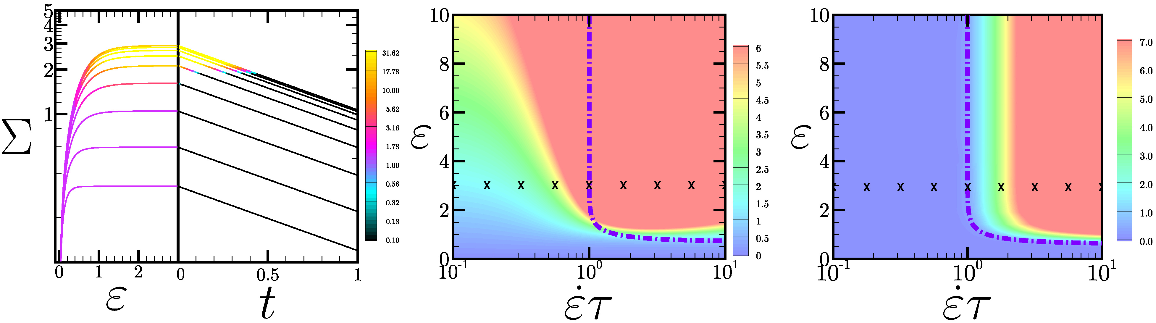 Figure 3
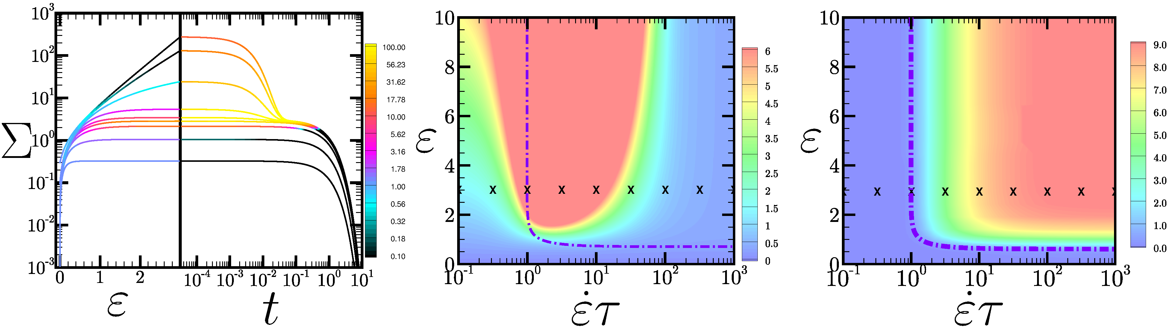 Figure 4
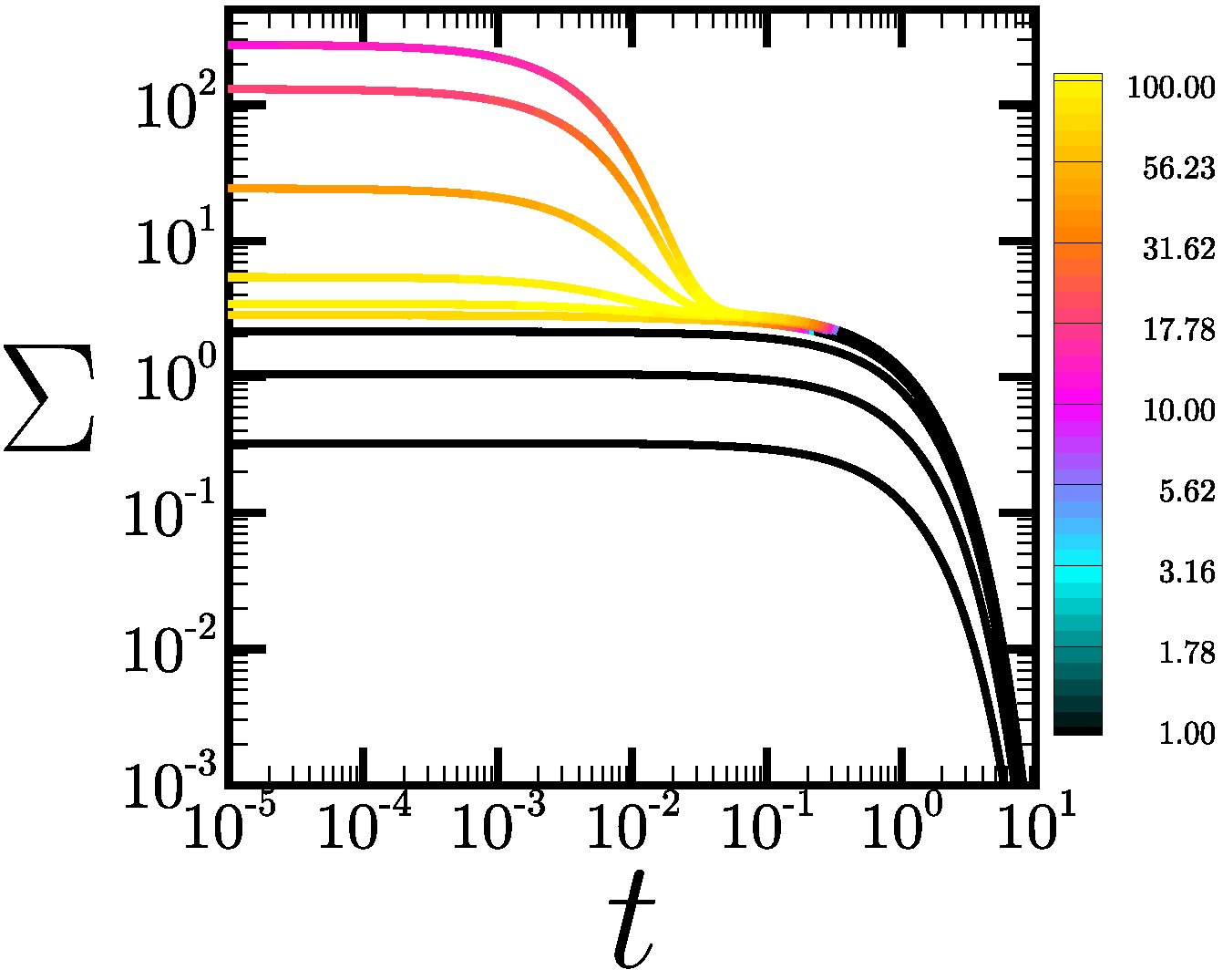 Figure 5
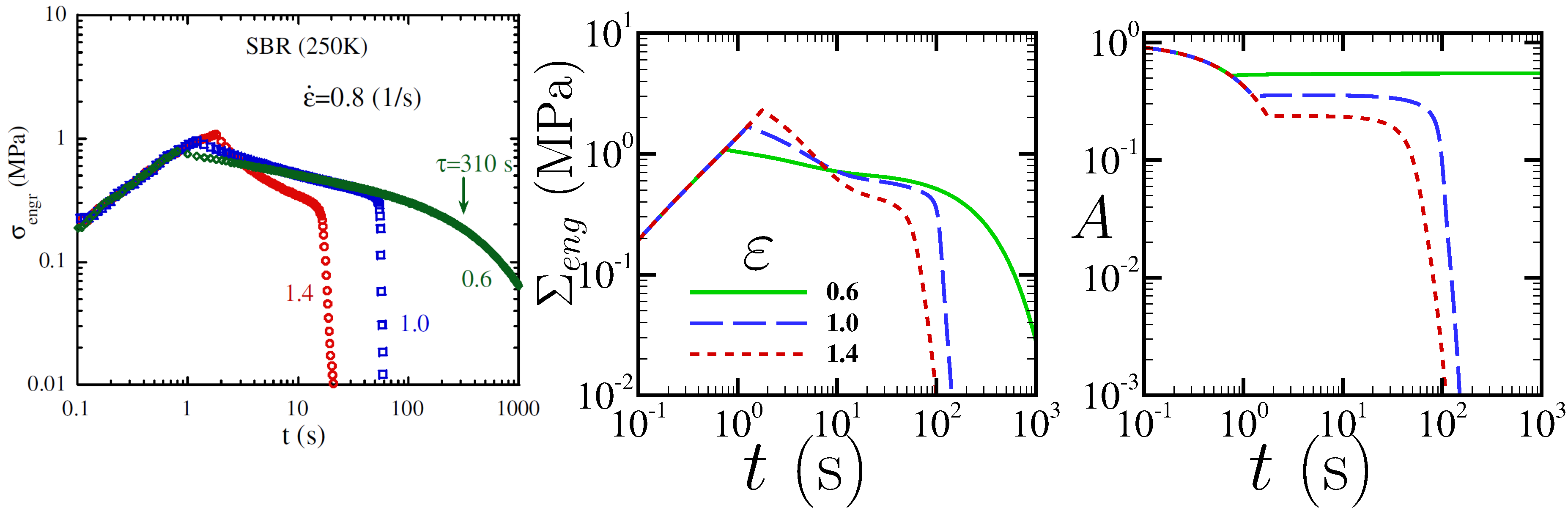 Figure 6
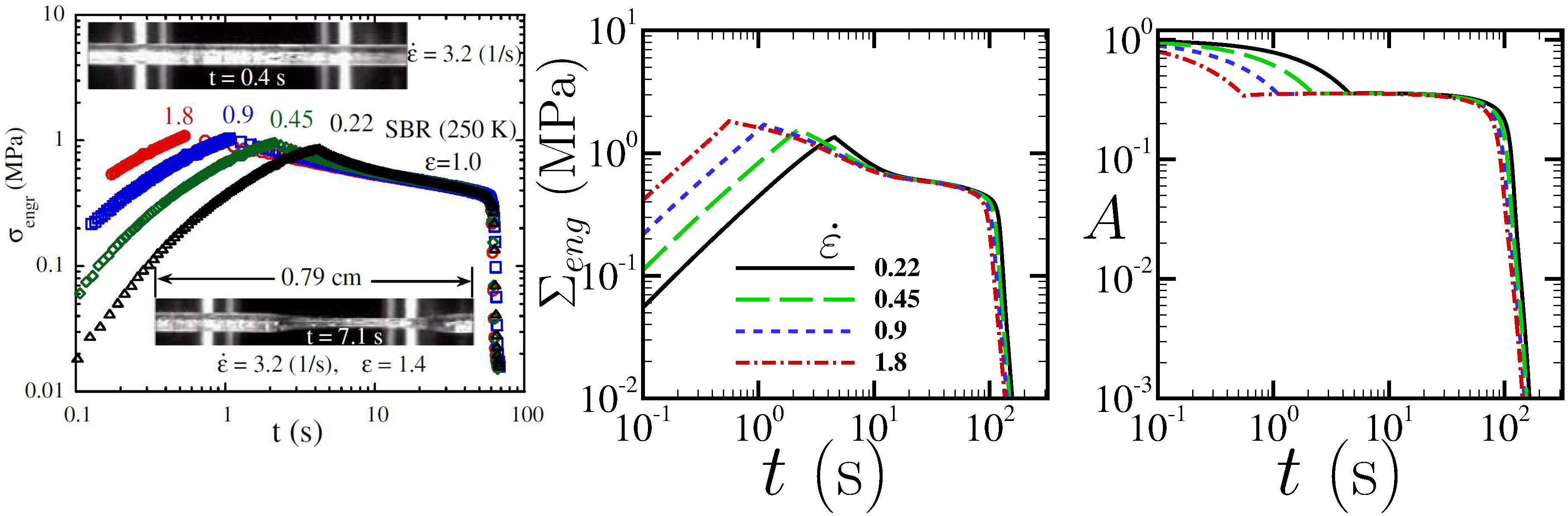 Figure 7
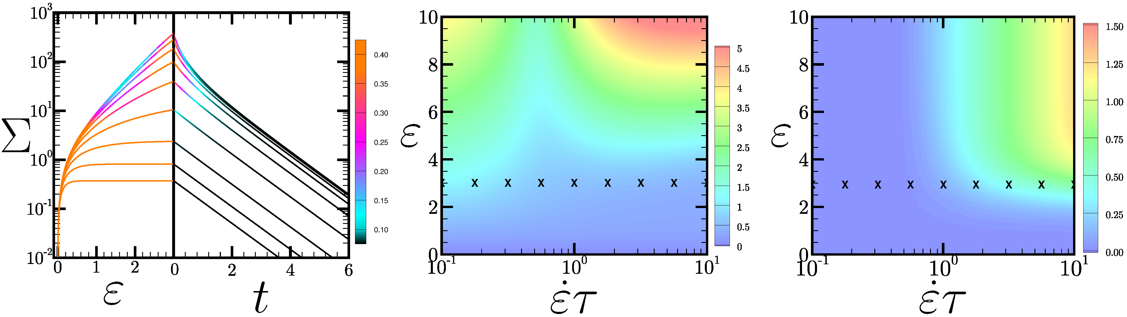 Figure 8
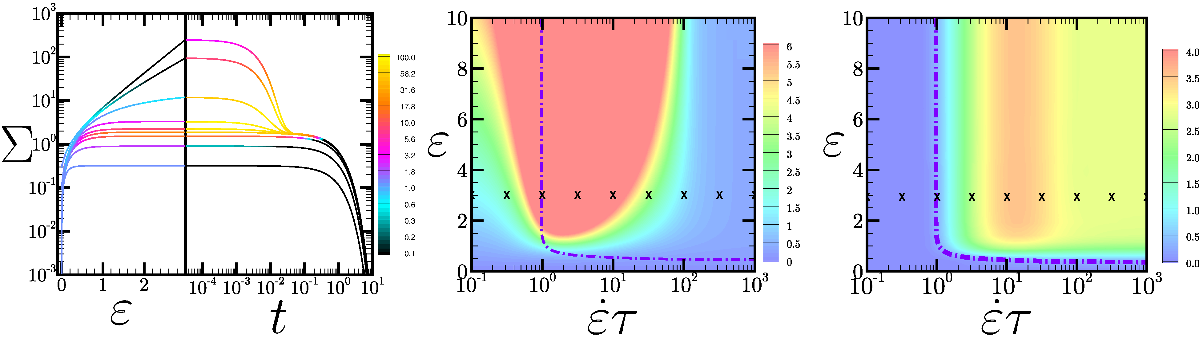 Figure 9
Peer Reviews
No public reviews on file for this paper yet. If you reviewed it on a platform where reviews are public (OpenReview, ICLR, NeurIPS, ICML), you can paste yours below so the community can read it here.
Videos
No videos yet. Explain this paper in a talk, walkthrough, or lecture? Add one.
Necking after extensional filament stretching of complex fluids
and soft solids
D. M. Hoyle
[email protected] http://community.dur.ac.uk/d.m.hoyle/ Department of Physics, University of Durham, Science Laboratories, South Road, Durham, DH1 3LE, United Kingdom
S. M. Fielding
Department of Physics, University of Durham, Science Laboratories, South Road, Durham, DH1 3LE, United Kingdom
Abstract
We perform linear stability analysis and nonlinear slender filament simulations of extensional necking in complex fluids and soft solids, during the stress relaxation process following an interrupted strain ramp. We start by deriving analytical criteria for necking within a highly simplified and generalised scalar constitutive model. Within this, we find two different possible modes of necking: one associated with an upward curvature in the stress relaxation function on a log-linear plot, and another related to a carefully defined ‘elastic’ derivative of the tensile force with respect to an imagined sudden strain increment. We showed these two criteria to agree fully with simulations of the Oldroyd B and Giesekus models of polymeric solutions, and with the Rolie-Poly model of more concentrated polymeric solutions and melts, without polymer chain stretch. With chain stretch included, we find a slightly more complicated analytical criterion for necking during the stress relaxation, although with key ingredients that closely mirror counterpart ingredients of the simpler criteria obtained within the scalar model. We show this criterion to agree fully with slender filament simulations of the Rolie-Poly model with chain stretch, and with the scenario discussed by the Copenhagen group in Refs. Lyhne et al. (2009); Rasmussen and Yu (2011). In particular, we see delayed necking after strain ramps with an accumulated strain exceeding , for ramp rates exceeding the inverse chain stretch relaxation timescale. We discuss finally an analogy between this delayed necking following an interrupted extensional strain ramp and delayed shear banding following an interrupted shear strain ramp Moorcroft and Fielding (2013). This work provides the counterpart, for interrupted extensional strain ramps, to earlier papers giving criteria for necking in the protocols of constant imposed Hencky strain rate Hoyle and Fielding (2016a) and of constant imposed tensile stress or constant imposed tensile force Hoyle and Fielding (2016b).
I Introduction
Extensional flows provide an important test of the constitutive properties of complex fluids and soft solids such as linear Auhl et al. (2008), star Huang et al. (2016a), branched Barroso and Maia (2005); Liu et al. (2013a) and associative polymers Tripathi et al. (2006); Huang et al. (2016b), wormlike micellar surfactants Bhardwaj et al. (2007), bubble rafts Arciniaga et al. (2011) and colloidal suspensions Smith et al. (2010). Typically, they subject the underlying material microstructure (polymer chains, wormlike micelles, foam bubbles, etc.) to much more severe reorganisation than is experienced in shear. As a result, many nonlinear flow phenomena manifest themselves only in extension. An obvious example is the strain hardening seen in extensional flows of polymeric fluids RoloÌn-Garrido and Wagner (2009); Liu et al. (2013b), compared with thinning in shear. Extensional flows therefore provide an important way of characterising a material’s underlying microstructure and molecular architecture Münstedt and Auhl (2005); Lentzakis et al. (2013), and of discriminating between alternative constitutive theories. For reviews, see McKinley and Sridhar (2002); Malkin et al. (2014).
Perhaps the most common extensional flow experiment consists of taking an initially cylindrical filament (or planar sheet) and stretching it out in length under conditions of constant imposed Hencky strain rate Rasmussen et al. (2005); Burghelea et al. (2011); RoloÌn-Garrido and Wagner (2014); Wagner and RoloÌn-Garrido (2013). Other commonly used protocols are those of constant imposed tensile stress Alvarez et al. (2013); RoloÌn-Garrido et al. (2011), constant imposed tensile force Szabo et al. (2012); Wagner and RoloÌn-Garrido (2012), large amplitude oscillatory extension Rasmussen et al. (2007), or a ramp of finite strain amplitude that is then interrupted Bhattacharjee et al. (2003); Wang et al. (2007); Wang and Wang (2008); Wang et al. (2011); Rasmussen and Yu (2011); Huang et al. (2012); Hawke et al. (2015); Huang and Rasmussen (2016). The usual aim in any such experiment is to draw the sample out in as uniform a way as possible, in order to characterise its homogeneous flow response. Almost ubiquitously observed, however, is the phenomenon of necking Barroso and Maia (2005); Liu et al. (2013a); Burghelea et al. (2011); Arciniaga et al. (2011); Smith et al. (2010); Andrade and Maia (2011); Malkin et al. (2014); Wang et al. (2007), in which some region along the filament’s length thins more quickly than the rest, forming a neck. This often leads the filament to fail altogether at the neck, aborting the experiment.
Necking has been studied theoretically in Refs. Considère (1885); Hutchinson and Neale (1977); Ide and White (1977); Malkin and Petrie (1997); Olagunju (1999, 2011); Joshi and Denn (2003, 2004); Hassager et al. (1998); McKinley and Hassager (1999); Rasmussen (2013); Cromer et al. (2009); Eastgate et al. (2003); Hoyle and Fielding (2016a, b). Much early work was based on the Considère criterion for necking in solids Considère (1885), which predicts instability to necking in any regime where the tensile force in the filament is a declining function of the accumulated Hencky strain . However, in failing to take account of the rate of extension, this criterion is unable to address necking in viscoelastic materials, in which the rate at which the strain is applied (compared with the material’s intrinsic rate of stress relaxation ) is an important variable, alongside the total accumulated strain.
Motivated by this shortcoming, we recently provided criteria for necking in viscoelastic fluids and soft solids, separately for the protocols of constant imposed Hencky strain rate Fielding (2011); Hoyle and Fielding (2015, 2016a), constant imposed tensile stress Hoyle and Fielding (2016b), and constant imposed tensile force Hoyle and Fielding (2016b). These criteria were derived analytically within a simplified constitutive model of highly generalised form, with the aim that they should be as fluid-universal as possible, independent of the particular assumptions of any given constitutive model. They were then confirmed against numerical simulations of several of the most widely used constitutive models of dilute polymer solutions, concentrated solutions and melts of entangled linear and branched polymers, wormlike micellar surfactants, and soft glassy materials.
In the present manuscript, we turn to another important filament stretching protocol: that of an interrupted extensional “strain ramp” Bhattacharjee et al. (2003); Wang et al. (2007); Wang and Wang (2008); Wang et al. (2011); Rasmussen and Yu (2011); Huang et al. (2012); Hawke et al. (2015); Huang and Rasmussen (2016). In this protocol, an initially uniform cylindrical filament (or planar sheet) is subject to the switch-on at some time of a constant Hencky strain rate . (The overbar signifies the nominal strain rate averaged along the filament’s length. Should the flow become heterogeneous, the actual strain rate will vary as a function of position locally along the filament.) The filament length then increases as . At some time the strain is switched off and the sample is held in its strained state with new length for all subsequent times. The tensile stress that accumulated during the initial straining process then progressively relaxes as a function of the time since the straining stopped. Indeed, this test is widely used to investigate a material’s stress relaxation properties Bhattacharjee et al. (2003); Sentmanat et al. (2005); Nielsen et al. (2008); Huang et al. (2012); Hawke et al. (2015); Huang and Rasmussen (2016) and the associated damping function Barroso and Maia (2002); RoloÌn-Garrido and Wagner (2009).
Observed in many cases during the process of stress relaxation after the straining has stopped, however, is a delayed necking instability, which often leads the filament to fail entirely Sentmanat et al. (2005); Nielsen et al. (2008); Huang et al. (2012); Wang et al. (2007); Wang and Wang (2008); Wang et al. (2011). Any such failure clearly hampers attempts to characterise a material’s stress relaxation properties: when the sample fails the stress falls catastrophically and the measurement terminates.
This phenomenon of delayed necking after an interrupted extensional strain ramp was studied by numerical simulation in the insightful earlier work of Refs. Lyhne et al. (2009); Rasmussen and Yu (2011). These studies showed that the effect could be completely accounted for within continuum models of polymer rheology, based on long-standing concepts of tube dynamics Doi and Edwards (1986), provided these are augmented to include the concept of chain stretch Fang et al. (1999); Mead et al. (1998); McLeish and Larson (1998); Schieber et al. (2003). Important physical conclusions of the work were that (i) during the initial straining process, the samples could be extended to nominal Hencky strains without necking, (ii) after the straining stops, samples that had been strained up to would remain intact, avoiding any necking instability, while (iii) any samples that had been strained beyond would show delayed necking after the straining stops, and finally that (iv) this delayed necking sets in on a timescale much shorter than the material’s terminal reptation time.
The aim of the present manuscript is to build on the simulation results of Ref. Lyhne et al. (2009); Rasmussen and Yu (2011) by performing analytical linear stability calculations complemented by nonlinear simulations of necking in complex fluids and soft solids, for this interrupted strain ramp protocol. In particular, we shall analytically derive criteria for the onset of necking after the end of the straining process. We do this first within a simplified constitutive model written in a highly generalised form, with the aim that the criteria we provide are as fluid-universal as possible, independent of the assumptions of any particular constitutive model. We then show the criteria to be in excellent agreement with the behaviour of the Oldroyd B and Giesekus models of polymer solutions, and the Rolie-Poly model of concentrated solutions and melts of entangled linear polymers, and wormlike micellar surfactant solutions, provided chain stretch is ignored.
We then proceed to incorporate polymer chain stretch. With this included, we find a slightly more complicated analytical criterion for the onset of necking. However the key ingredients of this updated criterion closely mirror counterpart ingredients of the simpler criteria derived within the generalised model (and checked against Oldroyd B, Giesekus and non-stretch Rolie-Poly). We show that this new criterion agrees fully with our numerical simulations of the Rolie-Poly model with chain stretch included, and with the conclusions of Refs. Lyhne et al. (2009); Rasmussen and Yu (2011): in particular in predicting delayed necking after fast strain ramps with a total accumulated strain exceeding . We also perform a quantitative comparison of our simulations with the experiments of Ref. Wang et al. (2007), demonstrating excellent agreement. Finally, we elucidate a close analogy between this scenario of delayed necking following an interrupted extensional strain ramp and that of delayed shear banding following an interrupted shear strain ramp, as first put forward by one of the present authors together with Moorcroft in Ref. Moorcroft and Fielding (2013).
Throughout we focus on the case of a highly viscoelastic filament of sufficiently large initial cross sectional area that surface tension can be safely ignored in comparison with the bulk viscoelastic stresses, at least in considering the initial stages of neck formation. In this way, we ignore any filament breakup and beading instabilities driven by surface tension Clasen et al. (2006); Tembely et al. (2012); Vadillo et al. (2012); Webster et al. (2008); McIlroy and Harlen (2014).
The paper is structured as follows. In Sec. II we introduce the continuum models to be studied. Sec. III defines the flow protocol and geometry. In Sec. IV we perform a linear stability analysis to derive criteria for the initial onset of necking, and show them to be in excellent agreement with numerical simulations of several of the most commonly used constitutive models of polymeric fluids. Sec. V reports our simulations of nonlinear necking dynamics, once the necking perturbations have grown to be no longer small. In particular, we quantitatively compare our calculations with the experiments of Ref. Wang et al. (2007), demonstrating excellent agreement. In Sec. VI we discuss the analogy with shear banding after an interrupted shear strain ramp. Sec. VII contains our conclusions and outlook for future work.
While this manuscript is intended to be self contained in its own right, it would best be read after our earlier manuscripts in Refs. Hoyle and Fielding (2016a, b). In making this manuscript self-contained, the discussion in some places (particularly the earlier introductory sections) inevitably mirrors that of those earlier papers Hoyle and Fielding (2016a, b) to some degree.
II Rheological models
We assume the stress in a fluid element at position at time to comprise a Newtonian solvent contribution with viscosity , an isotropic contribution from a pressure field , and a viscoelastic contribution arising from the internal fluid microstructure (polymer chains, wormlike micelles, etc.), giving:
[TABLE]
In this expression, is the symmetrised strain rate tensor, with , and is the velocity field of the fluid flow. We assume creeping flow in which the condition of force balance gives:
[TABLE]
We also assume the flow to be incompressible, with the pressure field determined by the requirement that the velocity field remains divergence free:
[TABLE]
The dynamics of the viscoelastic stress comprises loading driven by the velocity gradients of any imposed flow, combined with relaxation back towards an unstressed equilibrium state. For any given fluid, these two physical processes are governed by a rheological constitutive equation. In this work we shall consider several different constitutive models, which we specify now.
The phenomenological Oldroyd B model describes the rheology of a dilute polymer solution by representing each polymer molecule as a dumbbell formed of two beads linked by a Hookean spring. The viscoelastic stress
[TABLE]
in which is a constant modulus and is a conformation tensor formed from the ensemble average of the outer dyad of the dumbbell end-to-end vector . This is assigned dynamics in flow as follows:
[TABLE]
with a relaxation time . The upper convected derivative
[TABLE]
The Giesekus model describes more concentrated polymer solutions by incorporating an anisotropic drag characterised by a parameter , with . This encodes the basic idea that the relaxation dynamics of any dumbbell is altered when its surrounding dumbbells are oriented Larson (1988), giving the modified dynamical equation
[TABLE]
The Oldroyd B model is recovered for .
The Rolie-Poly model Likhtman and Graham (2003) describes more concentrated solutions or melts of entangled linear polymers, or solutions of wormlike micellar surfactants. It is based on the tube theory of polymer dynamics Doi and Edwards (1986), in which any given polymer chain (or wormlike micelle) is assumed to be dynamically restricted by entanglements with its surrounding chains (or micelles). Over time the chain refreshes its configuration by a process of ‘reptation’, i.e., curvilinear diffusion back and forth along the tube contour, on a timescale . An applied flow also induces stretch of any chain along its tube. This relaxes on a timescale , providing an additional mechanism for relaxing entanglement points, known as ‘convective constraint release’ Marrucci (1996); Ianniruberto and Marrucci (2014a, b). With all these processes accounted for, the conformation tensor , in which is the end-to-end vector of a polymer chain, has dynamics:
[TABLE]
In this equation, is the trace of the conformation tensor. The parameter sets the degree of convective constraint release, with .
The timescales of reptation and chain stretch relaxation are assumed to be in the ratio
[TABLE]
where is the number of entanglements per chain. For highly entangled chains, , reptation occurs much more slowly than the relaxation of chain stretch: . In this case, for flow rates much less than , we can use the simpler, non-stretching form of the model:
[TABLE]
in which the limit has been taken upfront.
In both the Giesekus and Rolie-Poly models, the viscoelastic stress is specified in terms of the conformation tensor by Eqn. II.4, as in the Oldroyd B model. Throughout we use units in which the modulus , the relaxation time (Oldroyd B and Giesekus) or (Rolie-Poly), and the initial filament length .
III Flow protocol and geometry
Before any flow commences, the filament is assumed to be prepared in the shape of an undeformed uniform cylinder of length in the direction, with a cross sectional area in the plane. All viscoelastic stresses are taken to be well relaxed, with .
At some time , the filament is subject to the switch-on of a Hencky strain rate that stretches the filament out along the axis, with a flow field
[TABLE]
(As noted above, the overbars signify that is the nominal Hencky strain rate averaged along the length of the filament. Once any necking arises, the strain rate will vary locally as a function of position along the filament’s length.) This strain rate is held constant during a time interval , with the filament progressively drawing out in length according to . Its cross sectional area thins accordingly, to satisfy incompressibility. During this straining process, viscoelastic tensile stresses develop as a function of the time since the inception of the flow.
After a time , once a strain has accumulated and the sample has attained a new length , the strain rate is set back to zero and the filament is held in this strained state with length for all times , during which the viscoelastic stresses progressively relax back to zero.
We shall call this procedure, comprising both the initial straining and the stress relaxation that follows it, a ‘strain ramp protocol’. Any such ramp is fully specified by the two parameters , which respectively denote the total strain applied and the rate at which it is applied. Clearly, during the initial stretching process this strain ramp protocol coincides with the simpler protocol in which a constant Hencky strain rate is applied indefinitely, for all times after the initial switch-on. In earlier papers, we considered the dynamics of necking under those conditions Fielding (2011); Hoyle and Fielding (2016a). The key difference in the strain ramp protocol considered here is that the straining only persists for a finite time .
A key aim in what follows will be to determine whether, for any given fluid and strain ramp, necking will arise at any stage during the protocol. We further aim to determine whether any such necking will occur primarily during the initial stretching, or primarily during the stress relaxation that follows it (or roughly equally during both). Clearly, any case in which necking mainly occurs during the initial stretching process is already covered by our earlier results for the protocol of a constant Hencky strain rate applied indefinitely after the initial switch-ons Fielding (2011); Hoyle and Fielding (2016a). Therefore, our particular interest here will be in cases where necking is actually suppressed during the initial stretching process itself, then occurs with delayed onset during the subsequent stress relaxation.
Throughout we use a slender filament approximation Forest and Wang (1990); Olagunju (1999); Denn et al. (1975), which assumes the characteristic wavelengths of any necking variations in cross sectional area that develop along the filament’s length to be large compared with the filament’s radius. This in turn allows the flow variables to be averaged over the filament’s cross section at any location along its length. This approximation has been carefully tested against full axisymmetric simulations and shown to remain excellent even well into the nonlinear regime, where the amplitude of perturbations becomes large and the shear contribution might be expected to be large Vadillo et al. (2012). The dynamical variables to be considered are then the cross sectional area , the area-averaged fluid velocity in the direction , the extension rate , and any viscoelastic variables, as governed by the relevant rheological constitutive equations set out in Sec. II. The -average of the local extension rate is the nominal Hencky strain rate defined above.
Within this slender filament approximation, the mass balance condition (II.3) becomes
[TABLE]
The force balance condition (II.2) becomes
[TABLE]
in which the tensile force
[TABLE]
and the total tensile stress
[TABLE]
The Lagrangian derivative of any constitutive model (first two terms on the right hand side of Eqn. II.6) is written at this level of slender filament as:
[TABLE]
In any given fluid, the viscoelastic stress in Eqn. III.5 (recall the modulus in our units) is determined by the time-dependent components of the appropriate tensorial constitutive equation of Sec. II. To allow analytical progress in our linear stability calculation of Sec. IV below, however, we shall initially consider a simplified scalar constitutive model that denotes as a single variable , for which it then postulates highly generalised constitutive dynamics:
[TABLE]
This has separate loading and relaxation terms characterised by the functions and respectively. In the first part of our analysis below, we shall intentionally refrain from specifying any particular functional forms for and , in order that the criteria for necking that we shall derive are as fluid universal as possible, independent of the particular assumptions of any given constitutive model. For notational simplicity in this scalar model, we also renormalise the solvent stress . The total stress in Eqn. III.5 then simply reads
[TABLE]
For any ramp protocol, we set the initial cross sectional area of the filament . Note that this is in addition to our having set the initial cylinder length via our choice of length units above. However it is important to realise that we are not actually restricting the initial cylinder radius and length to be in any given ratio: any information about this quantity has simply been lost as a consequence of our having made the slender filament approximation.
For clarity, we shall drop the subscript E from the tensile stress for the rest of the paper.
IV Linear stability analysis
We now perform a linear stability analysis to determine the dynamics of the initial stage in the development of any neck that forms during the strain-ramp protocol defined above, in which a filament is strained at a rate during times to a total strain , then held at this strain for all subsequent times , during which any viscoelastic stresses that developed during the the straining process progressively relax.
Our main objective will be to derive fluid universal criteria for the onset of necking that do not depend on the detailed assumptions of any given constitutive model. To allow analytical progress, we shall first perform this calculation within the simplified, generalised scalar constitutive model defined in Sec. III. The analogous calculation for the fully tensorial models of Sec. II is equivalent in principle, but more cumbersome, and we shall not write it down. Readers are referred to Hoyle and Fielding (2016a) for details. Our numerical results below are, however, for the full tensorial constitutive models. As will be seen, these (mostly) agree extremely well with our criteria derived in the simplified scalar model.
In performing the linear stability analysis, we start by considering a homogeneous “base state” corresponding to a filament that remains a uniform cylinder, with the flow variables uniform along it, both during the initial straining and the stress relaxation that follows it. We shall denote this base state with the subscript [math]. We then add to it small amplitude perturbations describing any initial small heterogeneities along the filament’s length, which are the precursor of a neck. Expanding the governing equations to first order in the amplitude of these perturbations yields linearised equations that govern the dynamics of the perturbations. Our interest then lies in determining whether these perturbations grow to give a necked state, or decay to leave a uniform filament. If they do grow, our main aim is to determine at what stage during the experiment they first start to do so.
Consider first, then, a uniform base state corresponding to a filament that remains a perfect cylinder during the entire protocol. This obeys the homogeneous form of Eqns. III.2 to III.4, III.7 and III.8. The condition of mass balance accordingly gives
[TABLE]
The tensile force
[TABLE]
with tensile stress
[TABLE]
The viscoelastic variable evolves according to
[TABLE]
For the strain ramp protocol of interest here, the strain rate for times , and zero otherwise.
We now add to this homogeneous, time-evolving base state small amplitude heterogeneous perturbations, which are the precursor of any neck. As noted above, the dynamics of any necking perturbations under conditions of a constant Hencky strain rate, indefinitely sustained for all times , have already been studied in our earlier work Hoyle and Fielding (2016a). Because such conditions also pertain to the first (straining) phase of the ramp protocol considered here, our results from Hoyle and Fielding (2016a) automatically apply during that straining phase. Accordingly, we shall write here only the equations governing the fate of any necking perturbations after the straining has stopped, during the subsequent stress relaxation, when the base state’s strain rate . For convenience we decompose these perturbations into Fourier modes with wavevectors reciprocal to the distance along the filament’s length:
[TABLE]
Although the globally averaged (base state) strain rate after the straining has stopped, as just noted, flows with zero averaged strain rate will nonetheless develop internally along the filament as part of any necking process, characterised by . The variable determines the amplitude of any variations in cross sectional area along the filament, and so characterises the degree of necking at any time . A key aim in what follows will be to compute the time-dependence of this quantity for any given fluid and strain ramp protocol. In particular, we seek to distinguish regimes in which grows in time, leading to the development of a neck, from those in which it decays, leaving a uniform filament.
We now substitute expression IV.5 into Eqns. III.2 to III.4, III.7 and III.8. Expanding these then in successive powers of the perturbation amplitude, and retaining only terms of first order in that amplitude, gives a set of linearised equations governing the dynamics of the perturbations.
The linearised mass balance equation is
[TABLE]
The linearised force balance equation is
[TABLE]
and the linearised viscoelastic constitutive dynamics
[TABLE]
in which
[TABLE]
Here prime denotes differentiation with respect to a function’s own argument.
Combining these gives finally
[TABLE]
governed by the stability matrix
[TABLE]
We note that this stability matrix has inherited the time-dependence of the relaxing base state conformation and stress variables, , upon which it depends.
In writing the necking perturbations in this linearised analysis in the form , we have effectively assumed periodic boundary conditions between the two ends of the filament, thereby implicitly taking the filament to correspond to a torus being stretched. In Ref. Hoyle and Fielding (2016a), we showed that this simplifying assumption does not strongly affect any conclusions with regards the onset of necking. Nonetheless, our full nonlinear simulations in Sec. V use more realistic boundary conditions approximating the no-slip condition that pertains where each end of the filament meets the rheometer plates. We have checked that the early time dynamics of our nonlinear simulations, with quasi no-slip, match those of the linear stability analysis, with periodic boundary conditions.
We note, however, that the stability matrix does not in fact depend on the wavevector . In consequence, all Fourier modes are predicted to have the same dynamics. The mode that dominates the necking process in practice is therefore expected to be that which is seeded most strongly by external factors such as thermal or mechanical noise, endplate effects, or any slight imperfections in the way the sample is prepared initially. Among these, we expect the dominant seeding effect to be that imposed by the (quasi) no-slip condition where the filament meets the rheometer plates, as discussed in the previous paragraph. This inhibits stretching of the filament in the vicinity of the sample ends, thereby tending to seed a single neck mid-sample.
In Eqns. IV.10 and IV.11, then, we have arrived at an equation set governing the linearised dynamics of necking perturbations, in the regime where the amplitude of these perturbations remains small. As noted above, the stability matrix (IV.11) depends on the time-evolving base state. Our aim now is to relate any regime in which the degree of necking grows as a function of time to characteristic signatures in the time-evolution of the base state quantities in the stability matrix (IV.11). Furthermore, because those quantities by definition correspond to their counterpart globally measured rheological quantities in any regime where the necking perturbations remain small, these signatures in the base state directly correspond to counterpart signatures in the time-evolving globally measured rheological quantities. Our calculation will therefore allow us to report what signatures in the globally measured rheological quantities correspond to the development of necking. Given the correspondence just discussed, we now drop the 0 subscript from the base state quantities for simplicity.
Returning to the stability matrix IV.11, we note that its determinant and trace are respectively:
[TABLE]
and
[TABLE]
(The solvent viscosity is small compared with the zero shear viscosity of the viscoelastic component, so we ignore any subleading terms in here and throughout.) In the expression for the determinant, the second equality follows from the first by combining Eqn IV.4, differentiated with respect to time, with Eqn. IV.3. In any regime where (which holds unless is small), the two eigenvalues of IV.11 are
[TABLE]
and
[TABLE]
Had these eigenvalues been time-independent, they would have exactly prescribed the rate of growth (or decay) of necking perturbations. However, because the base state upon which the eigenvalues depend is time-dependent, the eigenvalues are themselves time-dependent. In particular, the first eigenvalue (IV.14) predicts that the necking perturbations grow (or decay) on a timescale commensurate with the timescale of the evolution of the base state, and so also of the evolution of the eigenvalue itself. Put differently: the rate at which the perturbations are predicted to change itself changes as fast as the perturbations themselves. To resolve this shortcoming, we performed a more thorough analysis (not detailed here), to show that the rate of growth (or decay) of necking associated with this eigenvalue at any time during the stress relaxation is in fact given by
[TABLE]
Here and throughout, the notation “log” denotes the natural logarithm.
The expression in the square brackets is always positive, because as the stress relaxes over time. In most regimes, the first term involving is also positive. Therefore, whether necking perturbations grow or decay via this mode is determined by the curvature on a log-linear plot of the stress relaxation function. Accordingly, we call this mode of necking the “stress curvature mode”.
The second eigenvalue (IV.15) is large, predicting a fast rate of growth (or decay) of necking perturbations on a short timescale compared with the much longer timescale on which the base state evolves. Concerns about the time-dependence of this eigenvalue are therefore much less serious: indeed, the eigenvalue predicts the rate of growth of necking perturbations at any time during the stress relaxation to excellent approximation:
[TABLE]
The second equality here can be proved by combining Eqns. IV.2 to IV.4. The derivative of the force with respect to strain that it contains needs very careful physical interpretation. Indeed, during the stress relaxation part of the strain-ramp protocol that is our concern here, no strain is actually being applied. The derivative denoted instead defines the incremental change in tensile force that would occur, were there to be a sudden incremental strain. In that very particular sense, this mode provides the equivalent in these viscoelastic materials of the Considère criterion for solids Considère (1885), which states that necking will occur in any regime where the force is a decreasing function of strain. This concept has been discussed in detail in our earlier papers Hoyle and Fielding (2016a, b).
Our analysis up to this point has been highly general, independent of the assumptions of any particular constitutive model. We now seek to apply the two necking criteria (“stress curvature” and “elastic Considère ”) that it has allowed us to derive to the various tensorial constitutive models of Sec. II. As a first step, we recall from Ref. Hoyle and Fielding (2016a) that the dynamics of our simplified scalar model of Eqn. III.7 can be made closely to mimic the Oldroyd B, Giesekus and non-stretch Rolie-Poly models by taking
[TABLE]
and
[TABLE]
The case gives a good approximation to the Oldroyd B model; to the Giesekus model; and to the non-stretch Rolie-Poly model. We shall use these simplified scalar forms of the three tensorial constitutive models in the next three subsections in turn to understand our numerical results for each of these three models. We emphasise that those numerical results were obtained in the full tensorial form of each model.
Recognising that during the stress relaxation the strain rate , and therefore that the total tensile stress and the viscoelastic strain variable coincide up to a prefactor , we shall use the symbols and interchangeably in what follows.
IV.1 Oldroyd B model
Our numerical results for the linearised necking dynamics of the full tensorial Oldroyd B model are shown in Fig. 1. The left panel shows the evolution of the stress: first (in the left subpanel of this left panel) as a function of strain while the sample is being stretched, and then (in the right subpanel) as a function of time during the relaxation of the stress after the straining has stopped. The colourscale superposed on this stress evolution indicates the rate of growth of necking perturbations at any stage in the protocol. (Any regime where the growth is negative, indicating decay, is shown in black.) As can be seen, no growth of necking occurs during the stress relaxation after the straining stops.
This can be understood by applying the two criteria developed in Sec. IV to the simplified scalar version of the Oldroyd B model. In this, the loading function . This gives , which is is always positive, both during the initial straining and after the straining stops. Accordingly, the elastic Considère mode remains stable at all times and causes no necking. The relaxation function , so after the straining has stopped the stress relaxes as , and therefore as . (We define the origin of time here to coincide with the end of straining. Previously we used it to indicate the start of straining.) The curvature of the stress decay on a log-linear plot is therefore zero, and the stress curvature mode predicts neutral stability with respect to necking. In this way, our analytically derived necking criteria, applied to the (simplified, scalarised) Oldroyd B model, predict no growth of necking perturbations during the stress relaxation post-straining, consistent with our numerical results in Fig. 1.
Some necking does however occur during the first part of the protocol, while the strain is being applied. As noted above, during this regime the flow coincides with the simpler protocol in which a constant Hencky strain rate is applied indefinitely for all times after the initial switch on. It is accordingly covered by our results in Ref. Fielding (2011); Hoyle and Fielding (2016a), to which the reader is referred for details. Here, we merely recall that in the Oldroyd B model any significant necking during straining arises only for strain rates , and via the stress curvature mode (generalised to the case of a non-zero strain rate; the stress curvature mode derived above holds for the particular case of zero strain rate).
The results just discussed in the left panel of Fig. 1 pertain to nine different strain ramp protocols, each with a different value of the imposed strain rate , but each with the same total applied strain , as indicated by the crosses in the middle panel of the figure. Beyond these nine individual runs, we also investigated a much fuller range of values of and . The results are represented in a compact way in the middle and right panels of Fig. 1.
In the middle panel, the colourscale at any coordinate pair denotes the total amount of necking that is predicted (at the level of this linear calculation) to accumulate during the first, straining part of a strain ramp protocol, in which a total strain of is applied at a constant rate . (In this way, the colourscale at the location of the nine crosses in the middle panel is effectively an integral over the data shown by the colourscale in the individual runs of the left subpanel of the left panel.)
In the right panel, the colourscale at each coordinate pair denotes the total amount of necking that further accumulates during the stress relaxation after the straining has stopped, for a ramp in which a total strain of has been applied at a constant rate . (In this way, the colourscale at the location of the nine crosses in the right panel is effectively an integral over the data shown by the colourscale in the individual runs of the right subpanel of the left panel.) This panel is essentially however redundant in this particular model, given that no further necking is predicted after the straining stops.
To summarise, in the Oldroyd B model some necking occurs during the straining process itself for imposed strain rates . No further necking is predicted to accumulate during the stress relaxation after the straining stops.
IV.2 Giesekus model
Our numerical results for the linearised necking dynamics of the full tensorial Giesekus model are shown in Fig. 2. These are presented in the same way as for the Oldroyd B model in Fig. 1 so we shall not explain the figure in detail again, but focus on drawing out the main similarities and differences between the two models.
In the left panel of Fig. 2, we see that the relaxation of the stress post-straining displays some initial upward curvature (in the log-linear representation used here):
[TABLE]
Associated with this upward curvature is some instability to necking at early times in this stress relaxation process, as seen by the bright patch in the colourscheme. This then gradually diminishes over time.
This behaviour can be understood within the simplified scalar form of the Giesekus model as follows. Its relaxation function (with Oldroyd B dynamics recovered only for ). Accordingly, during the stress relaxation after the straining has stopped, is more negative for larger values of sigma: the stress relaxation proceeds more quickly at earlier times, then progressively slows down as the stress decays. This indeed gives upward curvature of the rate of decay of the log-stress, as seen in the right subpanel of the left panel of Fig. 2. Accordingly, the stress curvature mode predicts instability to necking during the first part of the stress decay post-straining. (In contrast, the loading function of the scalar Giesekus model is the same as that of scalar Oldroyd B: . Accordingly, the elastic Considère mode remains stable in the Giesekus model, as in Oldroyd B, both during and after straining.)
The results in the left panel of Fig. 2 pertain to nine different strain ramps, each performed at a different value of the strain rate , but each with a total applied strain , as indicated by the crosses in the middle panel.
In the middle and right panels of Fig. 2 we explore a much fuller range of pairs of values of . As in Fig. 1 for Oldroyd B, the colourscale in the middle panel shows the total degree of necking that accumulates during the straining process for a ramp performed with any given pairing of . As noted above, during this straining part of the protocol the dynamics will coincide with those of the simpler protocol in which a constant strain rate is applied indefinitely for all times after the initial switch on. Accordingly, our results in the middle panel for the degree of necking that accumulates during straining follow directly from those in Fig. 3b of our earlier work of Ref. Hoyle and Fielding (2016a) for that protocol of a constant applied strain rate. In the right panel of Fig. 2, we show by the colourscale the total degree of necking that further accumulates during the stress relaxation after the straining stops, for a ramp that had been performed at any .
Compared with Oldroyd B, the most significant feature (at least of principle) in the Giesekus model is that some further necking does take place during the stress relaxation after the straining stops, for ramps with rates and strains , via the stress curvature mode. Comparing the colourscales in the middle and the right panels, however, we see that for any given ramp as specified by , the degree of necking that further accumulates after the straining stops (right panel) is always very modest compared with that which took place during the straining itself (middle panel). Indeed, for any case in which noticeable further necking might in principle have accumulated post-strain, the sample will almost certainly have anyway already failed entirely during the straining process itself.
Our analytical calculations in this section were performed in the simplified scalar version of the Giesekus model. In contrast, our numerical results in Fig. 2 are for the fully tensorial form of the model. To demonstrate the equivalence of these, Fig. 8 in the Appendix shows numerical results for the scalar version of the Giesekus model. Reassuringly, we see close agreement with those of Fig. 2 for the fully tensorial form. Further evidence of the close correspondence between the scalar version of each model (Oldroyd B, Giesekus, non-stretch Rolie-Poly) and its full tensorial counterpart is given in Ref. Hoyle and Fielding (2016a).
IV.3 Non-stretch Rolie-Poly model
Our numerical results for the linearised necking dynamics of the tensorial Rolie-Poly model without chain stretch (which we shall call the nRP model) are shown in Fig. 3, in the same format as in Figs. 1 and 2 for the Oldroyd B and Giesekus models. As can be seen in the left panel, after the straining stops the stress relaxes exponentially. During the first part of this stress relaxation, the system displays instability to necking for those ramps in which the stress had exceeded a threshold value approximately equal to two by the end of the straining process.
These observations can be understood within the simplified scalar version of the nRP model as follows. The relaxation function of this model is the same as for the (scalar) Oldroyd B model: . This gives exponential stress relaxation as a function of the time since the straining stops, consistent with the numerics: the stress decay plotted in log-linear representation is linear. In this way, the stress curvature mode is always stable against necking post-strain. In contrast, the loading function , and the factor that appears in the criterion for the elastic Considère mode to be unstable will become negative if sufficient stress (for ) develops during the straining process. Necking instability will then arise via this elastic Considère mode, and persist after straining stops until such a time as the stress decays to be again below , returning to positivity. This can be seen via the bright patch in the colourscale during the early part of the stress relaxation in the left panel of Fig. 3, for the ramps performed at the higher strain rate values.
In this left panel, we show results for strain ramps performed at nine different values of the imposed strain rate , with a total imposed strain in each case, as indicated by the crosses in the middle panel. We now consider more broadly in what region of the full plane of values of will become negative by the end of the straining process, and so by the start of the stress relaxation post-ramp, signifying instability to necking via the elastic Considère mode during the first part of the stress relaxation in the manner just described.
We studied this by integrating the model equations to obtain the base state stress as a function of accumulated strain and imposed strain rate . Doing so, we find to be negative at the end of the straining process, and so at the start of the stress relaxation, for values of above and to the right of the dot-dashed line in the middle and right panels of Fig. 3. In the limit of large strain rates , the criterion for to be negative tends to the condition
[TABLE]
as seen by the asymptote of the dot-dashed line at the the right hand side of these panels. In the limit of large strains , the criterion for to be negative tends to the condition , as seen by the asymptote at the top of the panels.
The right panel of Fig. 3 shows as a colourscale the total degree of necking predicted to accumulate during the entire stress relaxation after the straining has stopped as a result of this elastic Considère mode, as a function of the rate at which the strain had been applied, and the total strain imposed, . Consistent with the above analytical prediction, significant necking indeed occurs during the stress relaxation in the region of the plane of above the dot-dashed line.
This finding however proves to be mainly of pedagogical interest in this non-stretching version of the model, for the following reason. Comparing the right panel of Fig. 3 (showing the total necking that accumulates post-strain) with the middle panel, which shows the total necking accumulated during the straining process itself, we see that for any given pair of values of in which significant further necking might in principle accumulate after the straining stops, the sample will almost certainly have anyway failed altogether due to the very large degree of necking predicted during the straining process.
To summarise our results so far: in this and the previous two subsections, we have discussed the linearised necking dynamics of the Oldroyd B, Giesekus and non-stretch Rolie-Poly models during the stress relaxation after the straining stops. In the Oldroyd B model, we saw no further necking during the stress relaxation (beyond any that had already accumulated during straining in ramps for which ). In contrast, the Giesekus and non-stretch Rolie-Poly models do predict some further necking during the stress relaxation. In each case, however, a much larger degree of necking is predicted to have already occurred during the straining process itself, likely causing the filament fail altogether during the straining. The discussion of the previous three subsections can therefore be viewed as being primarily pedagogical, in helping us to understand the general conditions under which necking might occur after straining stops. Overall, perhaps the principal physical conclusion for the dilute or semi-dilute solutions modelled by the Oldroyd B and Giesekus models is that necking after straining stops is unlikely to be an important physical effect compared with any that takes place during the straining process itself.
In the next subsection, we turn to the Rolie-Poly model of concentrated solutions and melts of entangled linear polymers, and wormlike micellar surfactant solutions, with chain stretch included. In this case, we shall find an important new regime in which necking is suppressed during the straining process itself, due to the accumulation of chain stretch, but in which significant necking then occurs with a delayed onset after the straining stops, as the chain stretch relaxes on the short timescale , but before the orientational contribution to the stress relaxes on the much longer timescale . Such a physical scenario was predicted in the insightful earlier work of the Copenhagen group in this context of extensional necking Lyhne et al. (2009); Rasmussen and Yu (2011). (An analogous scenario was predicted by one of the present authors, with others, in the context of shear banding following a shear strain ramp Moorcroft and Fielding (2013); Adams and Olmsted (2009). We shall return to discuss this in Sec. VI below.) Here we build on that intuition, in particular by providing an analytical criterion for necking, and showing that it agrees fully with the regimes and rates of necking seen in the numerical simulations.
IV.4 Stretching Rolie-Poly model
Our numerical results for the Rolie-Poly model with chain stretch included are shown in Fig. 4, in the same format as in Figs. 1 to 3 for the Oldroyd B, Giesekus and non-stretch Rolie-Poly models. The new necking physics inherent to this model with chain stretch included is evident already in the left panel of Fig. 4, which shows the stress as a function of strain during the straining process, and as a function of time during the relaxation after the straining has stopped. The superposed colourscale indicates the rate of necking at any given strain (or time).
For the lowest imposed strain rates, , there is a modest rate of necking during the straining process itself, then essentially no further necking during the stress relaxation after the straining stops. For intermediate strain rates, , there is a high rate of necking during the straining. This originates from a significant vestige, in this stretching form of the model, of the elastic Considère mode of necking instability in the non-stretching model. (We shall return to discuss this in more detail below.) Fast necking is also predicted to continue after the straining stops (for the same reason). However that prediction of post-strain instability may be largely irrelevant: the very fast necking during the straining process itself is likely to cause the filament to fail altogether even before the straining stops.
The important new physics of the stretching model arises at high imposed strain rates, . In this regime, the sample is strongly stabilised against necking during the straining process by the accumulation of chain stretch. (This was discussed at length in our earlier work Fielding (2011); Hoyle and Fielding (2016a), and we do not repeat the details here.) Once the straining stops and the stress starts to relax, however, strong necking instability sets in.
Two separate regimes are evident in the stress relaxation. The first occurs on the fast timescale over which the chain stretch relaxes, with the stress quickly falling from its high initial value to an intermediate plateau value. During this first regime we see a fast rate of necking, which in fact becomes ever faster as that first regime proceeds to completion. The second regime occurs on the much slower timescale of reptation, with the stress finally decaying from its intermediate plateau value towards zero. The rate of necking falls in tandem with the stress, and the system is predicted to recover stability against necking once the stress falls below a threshold value . This predicted return to stability may be unimportant in practice, however, as the sample is likely to have failed altogether by this time.
The left panel of Fig. 4 pertains to nine different strain ramps, each performed at a different imposed strain rate , but with a total imposed strain in each case, as indicated by the crosses in the middle panel. In the middle and right panels we explore a much wider range of pairs of values of . As before, the colourscale in the middle panel shows the total degree of necking that accumulates during the straining process itself, for any given imposed . The right panel shows the total degree of necking predicted further to accumulate during the stress relaxation post-strain, again as a function of the variables that prescribed the ramp.
The important new physical regime in this stretching version of the Rolie-Poly model is that for which the imposed strain rate and the imposed strain . For such ramps, the accumulation of chain stretch stabilises the filament against necking during the straining process itself. A strong delayed necking then sets in as the chain stretch relaxes post-straining. For imposed strains (recall that is the asymptote of the dot-dashed line at high strain rates), no significant necking occurs either during or after straining. For value pairings above the dot-dashed line but with , the sample is likely to fail altogether during the straining process itself, with any prediction of further necking post-ramp accordingly essentially irrelevant.
We now sketch an analytical calculation to enable us to understand these numerical results of Fig. 4 in more detail. As ever, at the level of a slender filament approximation the condition of mass balance gives:
[TABLE]
The force balance condition gives
[TABLE]
in which the tensile force
[TABLE]
and the total tensile stress
[TABLE]
The evolution in flow of the components and is given by Eqn. II.8. For simplicity in this analytical calculation we set the convective constraint release parameter , as in our numerical calculations of Fig. 4. (Additional numerical results shown in Fig. 9 in the Appendix confirm essentially the same physical scenario for , at the opposite end of the allowed range .) We adopt the notation for the viscoelastic tensile stress variable (recall that the modulus in our units) and for the chain stretch variable , and then further define the variable that quantifies the chain orientation. The components of Eqn. II.8 then yield equations of motion respectively for the variable that quantifies the polymer chain orientation, and for the variable that quantifies polymer chain stretch:
[TABLE]
in which (for )
[TABLE]
With these equations, we now perform the usual linear stability analysis, considering an underlying homogeneous base state corresponding to a cylinder that remains perfectly uniform, to which are then added small amplitude spatially varying perturbations, which are the precursor of a neck. We specialise to the time regime after the straining has stopped, recalling that the behaviour during straining has already been studied in Ref. Hoyle and Fielding (2016a).
The quantities pertaining to the homogeneous base state relax post-strain according to
[TABLE]
(We have omitted the subscript 0 used previously to denote the base state, having already noted above that the base state quantities coincide with their experimentally measured global rheological counterparts as long as the necking perturbations remain small.) From the second of Eqns. IV.26 one can show that the chain stretch relaxes back to its equilibrium value as a function of the time post-strain on a fast timescale as
[TABLE]
Note that for ramps with strain imposed at a fast rate , the initial value at the start of the stress relaxation (ie, at the end of the straining) can be large.
The variable associated with chain orientation relaxes on the much longer timescale according to
[TABLE]
Taken together, Eqns. IV.27 and IV.28 confirm that the tensile stress has two regimes of relaxation: the first associated with relaxation of the chain stretch variable on the fast timescale , and the second with relaxation of the chain orientation variable on the slower timescale , consistent with our numerical results in the left panel of Fig. 4.
Turning now to consider the small amplitude necking perturbations to the homogeneous underlying base state just discussed, we write linearised equations analogous to those in Eqns. IV.6 to IV.11 for the simplified scalar model. From these, it is possible to show (though we do not provide the details) that the rate of necking at any time during the stress relaxation process is given by
[TABLE]
(The quantity in the square brackets is always positive, because the trace decays as a function of time post-straining, .) This result contains two important factors that closely mirror analogous quantities in our earlier criteria for necking in the simplified scalar constitutive model. The first resembles the factor in the criterion for instability of the elastic Considère mode, but expressed now in terms of the chain orientation variable . (In the non-stretch Rolie-Poly model, at all times and .) The second resembles the factor of the stress curvature mode, but expressed in terms of the chain stretch variable .
We consider now the behaviour of each of these two factors in turn, as a function of the time after the straining stops. It is easy to show from the second of Eqns. IV.26 that the factor involving as written in its form in the first of Eqns. IV.29 obeys (for ) the relation
[TABLE]
This is always positive, and is in general large in magnitude because the stretch relaxation timescale is small. Having thus shown that the -curvature factor in Eqn. IV.29 is always positive, we recognise that any counterpart of the curvature mode of instability of the scalar model will always be stable in this context of the stretching Rolie-Poly model.
In consequence, the stability/instability to necking must be determined by the other, elastic Considère -like factor in Eqn. IV.29, with instability for . For high imposed strain rates, this orientational variable in the stretching Rolie-Poly model follows essentially the same dynamics as the variable in the non-stretching form of the model. Accordingly, the factor can become negative during strain ramps of sufficiently large strain performed sufficiently quickly. The region of the plane of imposed strain and strain rate for which is indeed negative by the end of the straining process is that above the dot-dashed line in the middle and right panels of Fig. 4. This coincides with the counterpart line shown in Fig. 3 for the non-stretching model, and asymptotes to as .
In any regime where indeed , Eqn. IV.30 substituted into Eqn. IV.29 tells us that the necking will develop with a characteristic rate that scales as , and that actually becomes progressively larger during the course of the first regime of stress relaxation post-straining, as the chain stretch relaxes from its large initial value to its equilibrium value .
The rate of growth of necking during the stress relaxation, as predicted by the analytical form in Eqn. IV.29, is plotted as a colourscale in Fig. 5. As can be seen by comparision with the right subpanel of the left panel of Fig. 4, it agrees well with with our simulation data.
Consistent with this analytical prediction, our numerical results shown by the colourscale in the right panel of Fig. 4 indeed display significant necking post-ramp for values of above the dot-dashed line. The middle panel of Fig. 4 shows the total necking predicted to accumulate during the straining process itself. As can be seen, ramps with values that lie above the dot-dashed line but that also satisfy (effectively recovering non-stretching Rolie-Poly dynamics) suffer sufficiently strong necking during the straining process itself that the filament is likely to fail altogether during straining, rendering any prediction of further necking post-strain largely irrelevant. The important new regime lies at high strain rates for imposed strains , where we find stability against necking during the straining process itself due to the accumulation of chain stretch, as discussed earlier in Ref. Hoyle and Fielding (2016a), but with a strong delayed necking after the straining stops. Ramps with imposed strains give no necking, even post-strain.
V Nonlinear dynamics
So far, we have discussed the dynamics of necking perturbations to an initially homogeneous underlying base state in the linear regime, where the amplitude of the perturbations remains small. We now consider the dynamics of necking out of that linear regime, when the amplitude of the perturbations is no longer small. To do so, we numerically evolve the nonlinear slender filament equations by discretizing them on a mesh, and time-stepping them using an explicit Euler algorithm for the spatially local terms and first order upwinding for the convective terms Press et al. (2007). Details are given in Ref. Hoyle and Fielding (2016a), together with a discussion of convergence on the space and time-steps.
The slender filament approach that we use throughout this work is not capable of properly implementing the no-slip condition that pertains where the fluid makes contact with the end-plates. To circumvent this, we use an approximate mimic of that condition by adopting an artificially divergent viscosity near each plate, according to Eqn. VII.1 of Ref. Hoyle and Fielding (2016a). This strongly limits the extensional stretching that can occur in the filament in the vicinity of each plate, and thereby constrains the filament area to remain close its initial value at each plate, even as the sample as a whole is stretched out. This has the effect of forcing the sample to thin more quickly in the middle than at its ends. This purely geometrical effect seeds a single neck mid-filament, which is then picked up by the mechanical necking instability that is our focus.
We perform these simulations in the Rolie-Poly model with chain stretch. Using this model, we attempt a quantitative comparison with the experimental data of Ref. Wang et al. (2007), focusing in particular on their monodisperse styrene-butadiene rubber (SBR 250K), which has modulus MPa, reptation time s, and chain stretch relaxation time s. For all these non-linear simulations we set , but also checked that our results are robust to reasonable variations in this value. In using the Rolie-Poly model we are adopting a course-grained approximation of an entangled linear polymer chain, whereas a multimode approach would be needed to capture the full quantitative behaviour of a real polymeric fluid Likhtman and Graham (2003). We therefore only expect to obtain qualitative agreement with experimental data.
The results are shown in Figs. 6 and 7. In Fig. 6 we compare the results of our theoretical calculations with the experiments of Ref. Wang et al. (2007) for the time-evolution of the tensile engineering stress during and after three different strain ramps, each performed at an imposed strain rate s, and with imposed strains and respectively. The middle panel shows the counterpart results for the tensile engineering stress in our numerical simulations of the Rolie-Poly model, with model and flow-protocol parameter values matched to those of the experimental data (and with an assumed solvent viscosity much smaller than the viscoelastic one, which, as noted above, does not affect the results). The right panel shows the evolution of the area at the filament’s midpoint, again obtained in our numerical simulations. Fig. 7 shows directly corresponding panels to those in Fig. 6, but now for four different strain ramps, each performed to a total strain , and with imposed strain rates , , and . In each case, our numerical simulations are seen to capture the overall qualitative features of the experimental data. Full quantitative agreement would not be expected, due to our use of a simplified constitutive model.
Each of these ramps shown in Figs. 6 and 7 lies in the regime where the imposed strain rate exceeds (or nearly exceeds, for the slowest ramp) the inverse chain stretch relaxation time. According to our arguments in Sec. IV above, then, we should expect the filament to be stabilised against necking during the straining process itself, but then to display delayed failure during the subsequent process of stress relaxation, provided the applied strain . Precisely this scenario is indeed observed: delayed failure is seen in all the ramps that have . In contrast, the ramp with in Fig. 6 displays full stress relaxation without filament failure.
VI Analogy with shear banding
In Ref. Moorcroft and Fielding (2013), one of the present authors together with Moorcroft studied the direct counterpart in shear of the protocol considered in this manuscript in extension: the imposition of a given total shear strain at an applied shear strain rate , after which the straining is switched off and the sample held in its strained state with shear strain for all times thereafter. The interest in that work lay in the possibility that delayed shear banding might arise during the process of stress relaxation after the straining stops, by analogy with the necking after an interrupted extensional strain as considered here. That delayed shear banding effect had also been considered in the earlier work of Ref. Adams and Olmsted (2009).
Fig. 9 of Ref. Moorcroft and Fielding (2013) showed their results for the stretching Rolie-Poly model in that protocol, for two different values of the imposed strain rate: one in the regime and another in the regime . As can be seen by direct comparison with the left panel of Fig. 4 in this work, an analogous scenario with the necking dynamics reported in this manuscript is indeed evident. In particular, for the case , significant instability to shear banding was seen both during the straining process itself, and during the stress relaxation that follows it. In the second case , instability to shear banding was suppressed during the straining process itself. However significant instability to shear banding then arose during the first part of the stress decay, on a timescale , associated with the relaxation of chain stretch. Stability against banding was later recovered on the the longer timescale on which the chain orientation progressively relaxed.
VII Conclusions
In this work, we have performed linear stability analysis and nonlinear slender filament simulations of extensional necking in complex fluids and soft solids, for the flow protocol in which an initially cylindrical filament (or planar sheet) is subject to a constant extensional strain rate for a given time interval, after which the strain rate is then set to zero. Our focus has been on the conditions required for a sample to neck during the process of stress relaxation after the end of the strain ramp.
We derived analytical criteria for necking during the stress relaxation, within a highly simplified and generalised scalar constitutive model. Within this model we found two different possible modes of necking. The first is associated with an upward curvature in the stress relaxation function shown on a log-linear plot. The second is related to a particular, carefully defined ‘elastic’ derivative of the tensile force with respect to an imagined sudden strain increment. We showed these two criteria to be in excellent agreement with the behaviour of the Oldroyd B and Giesekus models, and the Rolie-Poly model with chain stretch ignored.
With chain stretch included in the Rolie-Poly model, we obtained a slightly more complicated analytical criterion for necking during the stress relaxation, although with key ingredients closely mirroring counterpart ingredients of the simpler criteria derived within the simplified scalar model. We showed this criterion to be in full agreement with nonlinear slender filament simulations of the Rolie-Poly model with chain stretch, and with the scenario discussed by the Copenhagen group in Refs. Lyhne et al. (2009); Rasmussen and Yu (2011). In particular, we found delayed necking after ramps with a total accumulated strain exceeding , for ramp rates exceeding the inverse strain relaxation timescale.
We discussed finally a close analogy between this delayed necking following an interrupted extensional strain ramp and that of delayed shear banding following an interrupted shear strain ramp, as discussed earlier in Ref. Moorcroft and Fielding (2013); Adams and Olmsted (2009).
Acknowledgements – The research leading to these results has received funding from the European Research Council under the European Union’s Seventh Framework Programme (FP7/2007-2013) / ERC grant agreement number 279365.
Appendix I: correspondence of tensorial and scalar
constitutive models
Our analytical calculations in Sec. IV.2 were performed in the simplified scalar version of the Giesekus model. In contrast, our numerical results in Fig. 2 are for the fully tensorial form of the model. To demonstrate the equivalence of these, in Fig. 8 we show numerical results for the scalar version of the Giesekus model. Reassuringly, we see close agreement with those of Fig. 2 for the fully tensorial form.
Appendix II: effect of convective constraint release
In Fig. 4 of the main text, we demonstrated the necking dynamics post-straining of the Rolie-Poly model with chain stretch including, for a value of the convective constraint release parameter . In Fig. 9, we show the exactly counterpart results for a value at the other end of the allowed range , demonstrating qualitatively the same scenario even with convective constraint release included to its maximum allowable extent.
The reference list from the paper itself. Each links out to its DOI / PubMed record.
- 1Lyhne et al. (2009) A Lyhne, H. K Rasmussen, and O Hassager. Simulation of elastic rupture in extension of entangled monodisperse polymer melts. Physical Review Letters , 102:1–4, 2009.
- 2Rasmussen and Yu (2011) H. K Rasmussen and K Yu. Spontaneous breakup of extended monodisperse polymer melts. Physical Review Letters , 107(12):1–4, 2011.
- 3Moorcroft and Fielding (2013) R. L Moorcroft and S. M Fielding. Shear banding in time-dependent flows of polymers and wormlike micelles. Journal of Rheology , 58(1):103, 2013.
- 4Hoyle and Fielding (2016 a) D. M Hoyle and S. M Fielding. Criteria for extensional necking instability in complex fluids and soft solids. Part I: Imposed Hencky strain rate protocol. Journal of Rheology , 60(6):1347–1375, 2016 a.
- 5Hoyle and Fielding (2016 b) D. M Hoyle and S. M Fielding. Criteria for extensional necking instability in complex fluids and soft solids. Part II: Imposed tensile stress and force protocols. Journal of Rheology , 60(6):1377–1397, 2016 b.
- 6Auhl et al. (2008) D. W Auhl, J Ramirez, A. E Likhtman, P Chambon, and C Fernyhough. Linear and nonlinear shear flow behavior of monodisperse polyisoprene melts with a large range of molecular weights. Journal of Rheology , 52(3):801, 2008.
- 7Huang et al. (2016 a) Q Huang, S Agostini, L Hengeller, M Shivokhin, N. J Alvarez, L. R Hutchings, and O Hassager. Dynamics of Star Polymers in Fast Extensional Flow and Stress Relaxation. Macromolecules , 49(17):6694––6699, 2016 a.
- 8Barroso and Maia (2005) V. C Barroso and J. M Maia. Influence of long-chain branching on the rheological behavior of polyethylene in shear and extensional flow. Polymer Engineering & Science , 45(7):984–997, 2005.