User Assistance Characteristics of the USE Model Checking Tool
Frank Hilken (University of Bremen), Martin Gogolla (University of, Bremen)

TL;DR
The paper discusses how the USE tool supports modelers in analyzing, validating, and verifying UML and OCL models through graphical means and a plugin, enhancing usability for non-experts.
Contribution
It introduces the USE model validator plugin and demonstrates its integration, improving accessibility and effectiveness in formal model checking.
Findings
The USE tool facilitates interactive model analysis and validation.
The plugin enables non-experts to verify model consistency.
Graphical means aid in interpreting formal model descriptions.
Abstract
The Unified Modeling Language (UML) is a widely used general purpose modeling language. Together with the Object Constraint Language (OCL), formal models can be described by defining the structure and behavior with UML and additional OCL constraints. In the development process for formal models, it is important to make sure that these models are (a) correct, i.e. consistent and complete, and (b) testable in the sense that the developer is able to interactively check model properties. The USE tool (UML-based Specification Environment) allows both characteristics to be studied. We demonstrate how the tool supports modelers to analyze, validate and verify UML and OCL models via the use of several graphical means that assist the modeler in interpreting and visualizing formal model descriptions. In particular, we discuss how the so-called USE model validator plugin is integrated into the USE…
Click any figure to enlarge with its caption.
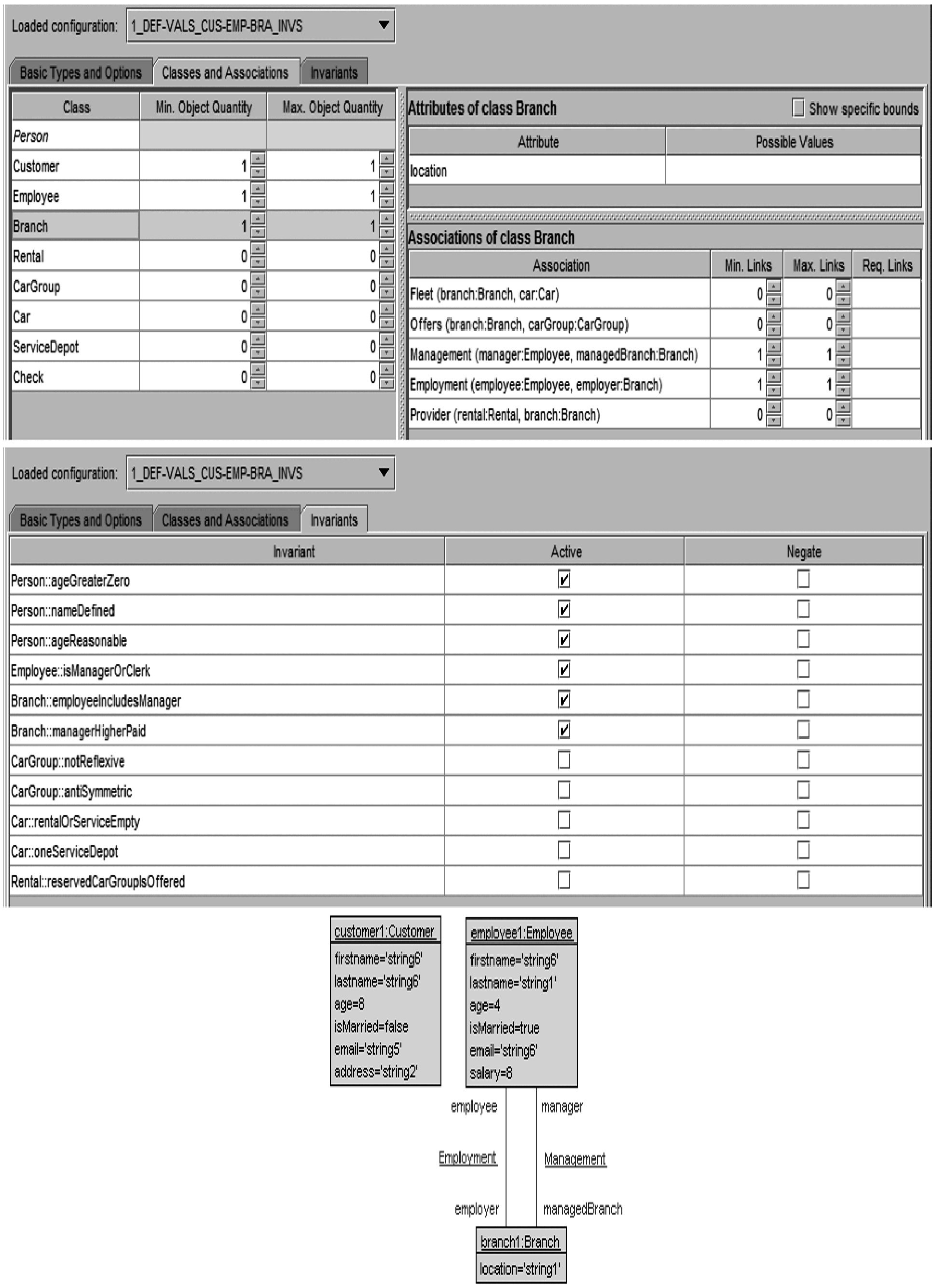 Figure 1
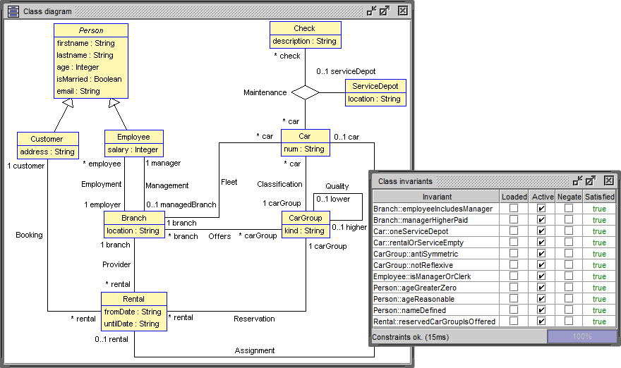 Figure 2
Peer Reviews
No public reviews on file for this paper yet. If you reviewed it on a platform where reviews are public (OpenReview, ICLR, NeurIPS, ICML), you can paste yours below so the community can read it here.
Videos
No videos yet. Explain this paper in a talk, walkthrough, or lecture? Add one.
User Assistance Characteristics
of the USE Model Checking Tool
Frank Hilken Martin Gogolla University of Bremen, Computer Science Department
28359 Bremen, Germany {fhilken,gogolla}@informatik.uni-bremen.de
Abstract
The Unified Modeling Language (UML) is a widely used general purpose modeling language. Together with the Object Constraint Language (OCL), formal models can be described by defining the structure and behavior with UML and additional OCL constraints. In the development process for formal models, it is important to make sure that these models are (a) correct, i.e. consistent and complete, and (b) testable in the sense that the developer is able to interactively check model properties. The USE tool (UML-based Specification Environment) allows both characteristics to be studied. We demonstrate how the tool supports modelers to analyze, validate and verify UML and OCL models via the use of several graphical means that assist the modeler in interpreting and visualizing formal model descriptions. In particular, we discuss how the so-called USE model validator plugin is integrated into the USE environment in order to allow non domain experts to use it and construct object models that help to verify properties like model consistency.
1 Introduction
Model-Driven Engineering (MDE) is an approach to software development concentrating on models in contrast to traditional code-centric development approaches. Within MDE, models are frequently formulated in the Unified Modeling Language (UML) with accompanying formal restrictions expressed in the Object Constraint Language (OCL). UML models are visually specified with several diagram kinds emphasizing structural and behavioral system aspects. Visual model descriptions offer a great potential for a user-friendly development process. Naturally, tools must take up the challenge and provide interfaces that support the developer in an easygoing way.
The present paper studies formal system descriptions employing UML class diagrams that are restricted by OCL invariants. The feature set of UML class diagrams that is handled here and the employed OCL elements pose a formal semantics. We regard this combination of UML and OCL as a formal method. The aim of this contribution is to demonstrate how the development of formal UML and OCL models can be supported by a user-friendly interface. Employing this interface it is possible to verify properties like model consistency.
2 Preliminaries
2.1 Running Example in UML and OCL
In UML, class diagrams describe the structure of models with classes and class attributes, which are templates for ’things’ and their properties, e.g. persons and their personal information. Additionally, associations put the classes in relation with each other. Figure 1 (left) shows the running example model description. It shows a Car Rental model with cars that are assigned to branches and their maintenance history. Additionally, there is a categorization for the cars into car groups. Finally, customers can rent cars from the branches that are run by their employees. The model uses a wide variety of UML features.
The class diagram is instantiated to create actual scenarios to describe car rentals. These system states are represented by UML object diagrams. They are restricted by the semantics of the class diagram and must satisfy all model inherent constraints given by, e.g. generalizations, multiplicities or compositions (not present in this model).
In addition to the UML descriptions, OCL invariants are used to employ further restrictions on the model that are not expressible by UML alone. These constraints are pictured in Fig. 1 on the right. They handle further relations between classes and ensure that the model does not allow system states that are not intended. For example, in the car rental model, the categorization of the car groups shall be cycle free and all employees must be connected to a branch, which cannot be handled by multiplicities, because there are multiple ways to represent this relation (Employment and Management).
The goal is to create a model description that can represent all intended situations but not more. Using model checking tools, the models can then be checked for certain properties. Usually, these properties regard safety, but other concerns can be checked as well. A valid system state must satisfy all model inherent constraints as well as all concrete constraints given by the OCL invariants.
2.2 Model Verification with the USE Tool
In this paper, the UML-based Specification Environment tool (USE, [3]) is used together with the so-called model validator plugin that allows to generate system states for UML/OCL models based on a relational logic encoding [7]. There is earlier work showing features of the USE tool that help to analyze and debug OCL expressions, namely the evaluation browser [2], but we concentrate on the model validator and its model checking aspects in this work.
In order for the model validator to search for a valid system state, it needs several inputs:
- •
A description of the model in the form of a class diagram optionally enhanced with invariants given as OCL expressions, see Fig. 1.
- •
A configuration, which defines the search space by providing the domain of basic data types (Integer, String and Real) and lower and upper bounds for classes and associations, i.e. specifies how many objects of each class – or links of each association respectively – are required and how many are allowed at most. Furthermore, the configuration contains rules for the assignments of class attributes, e.g. restricting domain values for certain attributes specifically. Finally, it allows to disable or negate invariants.
- •
Optionally a partial system state can be instantiated before the validation process that is used as a base for the task. The model validator adds elements to the system state until it: (a) conforms the bounds given in the configuration; and (b) is a valid system state as defined by the model. This can be seen as a lower bound on the model level.
- •
Smaller, model independent parameters include the choice of the SAT solver and bitwidth for the encoding of the model.
The second bullet point, the configuration, previously required the modeler to edit a text file containing key-value pairs to setup values for certain keys. The keys are determined by the model. For example for each class and association a lower and an upper bound is expected. The required values are mostly numbers, but more complex constructs were required to specify, e.g. preexisting links. This process requires a deep understanding of the existing syntax to enter the values. Moreover, special values exist for some keys with different meanings, e.g. unlimited upper bounds. Even experienced users regularly required the manual of the configuration.
In the following sections, we explain how a new graphical user interface helps to simplify the configuration process and reduce the necessity for a separate manual to the tool. Furthermore, additional analysis features of the tool are presented to help identify potential problems with the verification process caused by the inputs.
3 Iterative Instantiation of the Running Example
We now study for our running example four use cases corresponding to four model validator configurations that result in UML object diagrams. The basic structure of the GUI contains three tabs for (1) the datatypes, (2) the classes and associations, and (3) the invariants. We iteratively build up the configuration to generate multiple object diagrams.
Datatypes
First, only basic OCL types (e.g. Integer and String) are configured by giving bounds for their domain. For example, it is determined that integers may range from to and we want to use at most string values, which are automatically generated.
Parts of the Model
In the next step, the bounds for some of the classes of the model are configured and their relevant invariants are enabled. Figure 2 shows the configuration tabs and the resulting object diagram for this step. Here, the bounds for the classes Customer, Employee and Branch are set to 1..1 and all others are set to 0. The class Person is abstract and, therefore, cannot be setup. All invariants based on these classes are enabled as well and none are negated. These settings are useful to setup certain model verification tasks, e.g. invariant independence [4]. In addition, the associations Management and Employment are enabled with a bound configuration of 1..1. The object diagram shows the default string values for attributes, since these have not been specified further.
Full Model
Once parts of the model have successfully been instantiated, a configuration enabling all elements is built and run through the model validator. With these smaller steps per configuration, there is less margin for errors and if there is one, it is easier detectable.
Application Specific Values
Finally, application specific datatype values are employed for class attributes and basic types. They lead in the constructed object diagram to a state that seems more realistic, more domain specific than the previous object diagram. This also allows to specify that , e.g. address strings are not used for names.
4 Configuration GUI
First off, with the release of the configuration GUI the interface of configuration files was extended to allow storing multiple configurations in one file. These configurations can be named individually and the configuration GUI offers operations to manage them, e.g. cloning configurations, renaming or deleting them etc. This allows for an easy iterative construction of the configurations as shown in Sect. 3. The GUI also offers common file system operations to deal with the generated configuration files. For convenience, a configuration file with the same base name as the loaded model is automatically opened if one exists.
The GUI is split into three tabs that each cover a part of the configuration.111A detailed explanation of all three tabs in detail including screenshots can be found in [5]. The first tab is the basic types tab in which the domains for the basic types of OCL are defined. The domains can be defined as ranges or specific values that will be used by the model validator.
The second tab defines the model dependent bounds and domains. These include bounds for classes, attributes and associations as seen in the top of Fig. 2. The GUI only requires the values for the specific settings which eliminates the need to know the syntax for each model element, which makes the creation of configurations simpler and faster. Further, abstract classes cannot be setup, which is represented with non-editable fields in the GUI. If a value cannot be parsed, it is highlighted red and the modeler immedietly sees problems in the configuration. Features that require expert knowledge are hidden behind a checkbox.
The final, third tab, configures the invariants. Invariants can be individually deactivated and negated, which is required for certain verification tasks [4].
5 Analysis of Potential Modeling Problems
So far, we have shown how the user is assisted by the graphical user interface to setup the configuration of a verification task. However, besides a bad configuration, other problems can interfere with the checking process, in particular problems that the user is not aware of.
UML and OCL are rich languages filled with features for all kinds of purposes. Trying to support all of them is not only a lot of work, but also reduces the efficiency of the tools, the more features they support [6]. Therefore, it is common practice to restrict UML and OCL verification engines to a subset of the languages. This results in some features being completely unsupported and others only having limited support. Both categories pose problems to the users of the tools. If there are no means in place to detect the limitations, the outcome might differ from the user’s expectations and it is not feasible to keep track of all limitations from long tool manuals.
The verification engine of the USE tool, the model validator, has good support for UML and OCL, but also has limits. The underlying solving engine of the model validator is based on relational logic, which has great support for set operations and, thus, the integration of the OCL Set collection type is extensive. Adding support for the other collection types Bag, Sequence and OrderedSet would pose a significant overhead though, i.e. will be less efficient. This restriction to the Set collection type is particularly problematic for OCL navigation expressions. This expression allows to navigate the classes of the model using associations, more precisely the roles visible in Fig. 1. Usually a 1- navigation results in a set of elements, because at most one link is allowed between two objects, but under certain circumstances – namely starting with a set of objects rather than a single one – the navigation results in the duplicate preserving Bag type, because the result might contain the same value multiple times after the navigation. Due to the implicit nature of this effect and the strict interpretation of bags as sets in the model validator, simple expressions might already suffer unintended side effects. To help identify those potential problems, the occurrences are made visible to the modeler via a warning.
WARNING: Collect operation ‘[...].employee.age’ results in unsupported type ‘Bag’. It will be interpreted as ‘Set’.
\lst@ifdisplaystyle
The implicit type change from Set to Bag in OCL, which is consequently interpreted as Set by the model validator, brings more potential problems with it. Most OCL collection operations are defined on all collection types, but the results are different. Consider the operation sum(), which sums all integer elements of a collection. Here, the implicit conversion from Set to Bag is usually helpful when collecting, for example, the ages of persons to calculate an average. However, the interpretation as a Set does not work in this situation. To assist the user, the model validator checks for these situations and warns the modeler about this potential problem, which only the modeler can decide whether it needs to be addressed or not.
WARNING: The evaluation of sum expression ‘[...].employee.age->sum()’ might be wrong if source contains duplicates (Collection is interpreted as Set).
\lst@ifdisplaystyle
Other problems might arise from contradictions in the model itself. Navigations through the model can become quite long and obscure the resulting type. In these situations, typecasts like oclAsSet() need to be used to be able to compare differing types, but the textual representation of OCL alone is often insufficient to recognize such disparities. USE is able to structurally analyze the expressions in the model for type contradictions and gives hints about (sub)expressions that were determined to be contradicting, resulting in constant values.
WARNING: Expression ‘Set{ 1 } = Bag{ 1 }’ can never evaluate to true because ‘Set(Integer)’ and ‘Bag(Integer)’ are unrelated.
\lst@ifdisplaystyle
Finally, the underlying solving engine is bound to a bitwidth that has to be specified with the verification task. Setting the bitwidth as small as necessary increases the efficiency of the tool, thus we leave the task to the user to choose an appropriate bitwidth. But if the bitwidth is chosen too small, undefined behavior occurs when dealing with arithmetic operations exceeding the bitwidth. Finally, if the user is not aware of – or forgets – that the bitwidth is specified in two’s-complement, off-by-one errors can occur. In order to alleviate the problem, the model validator analyzes the configuration and model description for integer literals and checks them against the given bitwidth. If it is determined that the chosen bitwidth is too small, a warning is displayed including the appropriate bitwidth for the current model and configuration.
WARNING: The configured bitwidth is too small for the property Integer max value (237). Required bitwidth: 9 or greater.
\lst@ifdisplaystyle
6 Conclusion and Future Work
We have presented the USE tool together with its model validator plugin and have shown the steps necessary to apply model checking to given UML/OCL models. Furthermore, the simplifications of the process by integrating the graphical user interface have been discussed and the possibilities of the configuration GUI and the coverage mode are demonstrated. Finally, the possibilities of the model validator plugin to detect potential problems have been demonstrated to guide users in finding incompatibilities in their models.
Besides the configuration of the model domains and bounds, we have presented more aspects that have to be setup before a system state can be generated including the verification task itself, e.g. by manipulating the invariants. Future work should concentrate on the simplification of all steps of the setup and provide easy interfaces for each of them. Additionally, the evaluation of the configuration GUI and other presented interfaces is an ongoing process and new assistance features are constantly added and improved.
Acknowledgement.
We thank Subi Aili for his contributions to the configuration GUI – ideas and implementation – in his diploma thesis.
The reference list from the paper itself. Each links out to its DOI / PubMed record.
- 1[1]
- 2[2] Jens Brüning, Martin Gogolla, Lars Hamann & Mirco Kuhlmann (2012): Evaluating and Debugging OCL Expressions in UML Models . In Achim D. Brucker & Jacques Julliand, editors: Proc. 6th Int. Conf. Tests and Proofs (TAP 2012) , Springer, Berlin, LNCS 7305, pp. 156–162, 10.1007/978-3-642-30473-613 . · doi ↗
- 3[3] Martin Gogolla, Fabian Büttner & Mark Richters (2007): USE: A UML-Based Specification Environment for Validating UML and OCL . Science of Computer Programming 69, pp. 27–34, 10.1016/j.scico.2007.01.013 . · doi ↗
- 4[4] Martin Gogolla, Mirco Kuhlmann & Lars Hamann (2009): Consistency, Independence and Consequences in UML and OCL Models . In Catherine Dubois, editor: Tests and Proofs, TAP , Lecture Notes in Computer Science 5668, Springer, pp. 90–104, 10.1007/978-3-642-02949-38 . · doi ↗
- 5[5] Frank Hilken & Martin Gogolla (2016): User Assistance Characteristics of the USE Model Checking Tool . Technical Report, University of Bremen. Available at http://www.db.informatik.uni-bremen.de/publications/intern/HG 2016.pdf .
- 6[6] Frank Hilken, Philipp Niemann, Martin Gogolla & Robert Wille (2014): Filmstripping and Unrolling: A Comparison of Verification Approaches for UML and OCL Behavioral Models . In Martina Seidl & Nikolai Tillmann, editors: Tests and Proofs, TAP , LNCS 8570, Springer, pp. 99–116, 10.1007/978-3-319-21155-812 . · doi ↗
- 7[7] Mirco Kuhlmann & Martin Gogolla (2012): From UML and OCL to Relational Logic and Back . In Robert France, Juergen Kazmeier, Ruth Breu & Colin Atkinson, editors: Proc. 15th Int. Conf. Model Driven Engineering Languages and Systems (Mo DELS’2012) , Springer, Berlin, LNCS 7590, pp. 415–431, 10.1007/978-3-642-33666-927 . · doi ↗