Recovering 3D Planar Arrangements from Videos
Shuai Du, Youyi Zheng

TL;DR
This paper introduces a novel optimization framework for reconstructing 3D planar arrangements from videos by leveraging structure-guided dynamic tracking and planar constraints, improving accuracy in camera motion and structure estimation.
Contribution
It presents a new structure-guided dynamic tracking algorithm and a reconstruction pipeline that enforces planar constraints, enhancing 3D reconstruction from videos.
Findings
Effective localization of structure correspondence across dense frames
Faithful reconstruction of camera motion and 3D structure
Improved robustness over traditional point correspondence methods
Abstract
Acquiring 3D geometry of real world objects has various applications in 3D digitization, such as navigation and content generation in virtual environments. Image remains one of the most popular media for such visual tasks due to its simplicity of acquisition. Traditional image-based 3D reconstruction approaches heavily exploit point-to-point correspondence among multiple images to estimate camera motion and 3D geometry. Establishing point-to-point correspondence lies at the center of the 3D reconstruction pipeline, which however is easily prone to errors. In this paper, we propose an optimization framework which traces image points using a novel structure-guided dynamic tracking algorithm and estimates both the camera motion and a 3D structure model by enforcing a set of planar constraints. The key to our method is a structure model represented as a set of planes and their arrangements.…
Click any figure to enlarge with its caption.
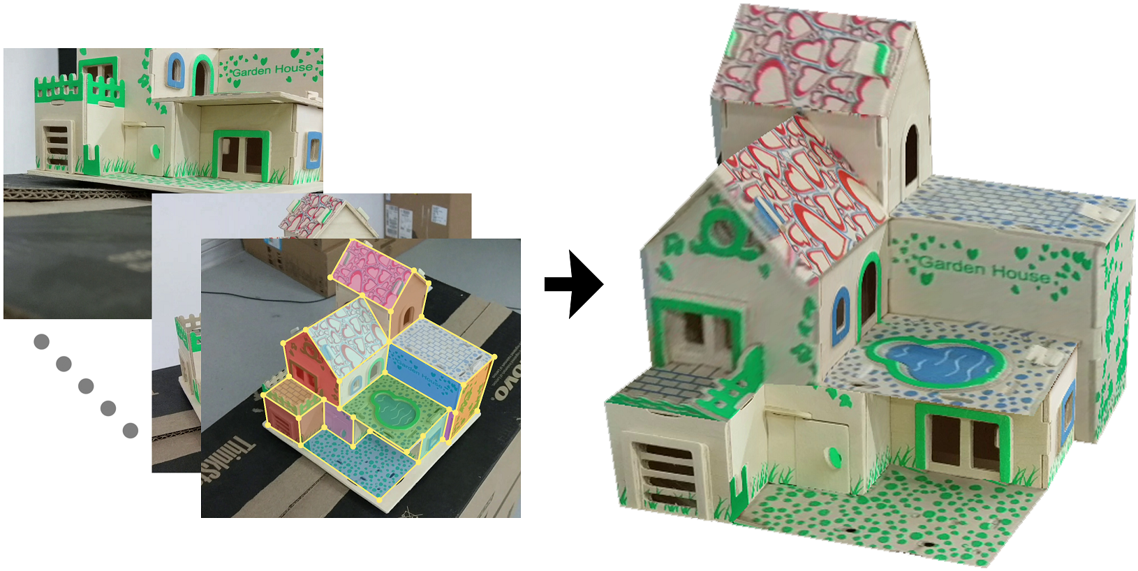 Figure 1
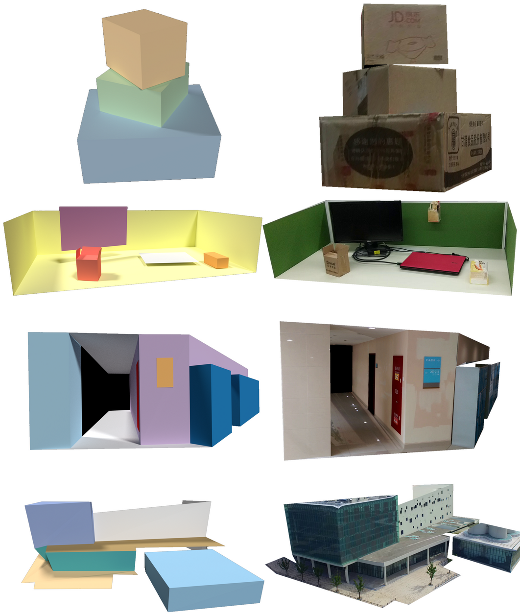 Figure 10
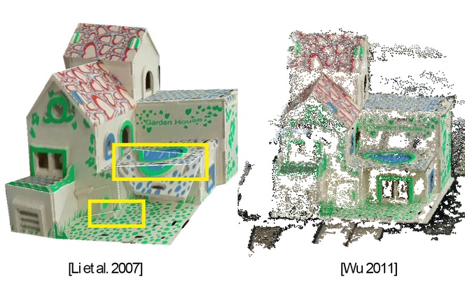 Figure 11
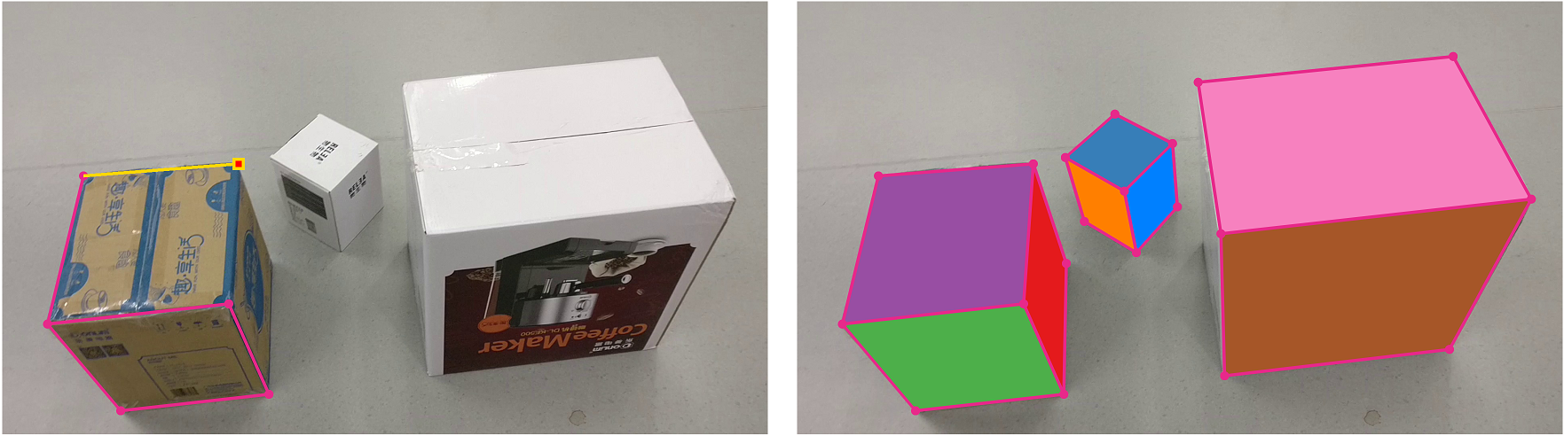 Figure 2
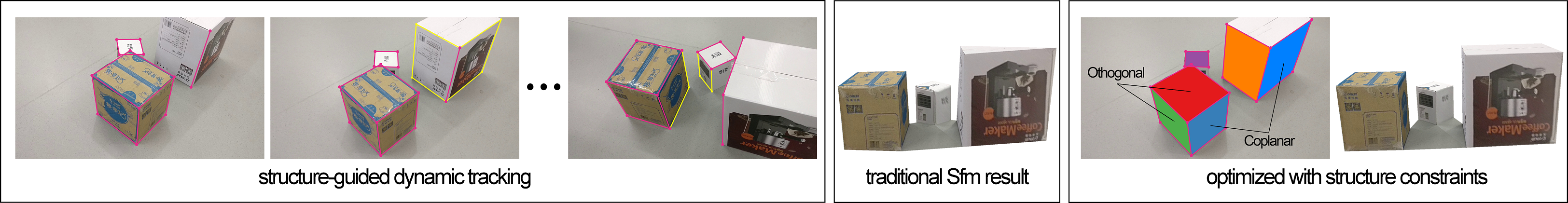 Figure 3
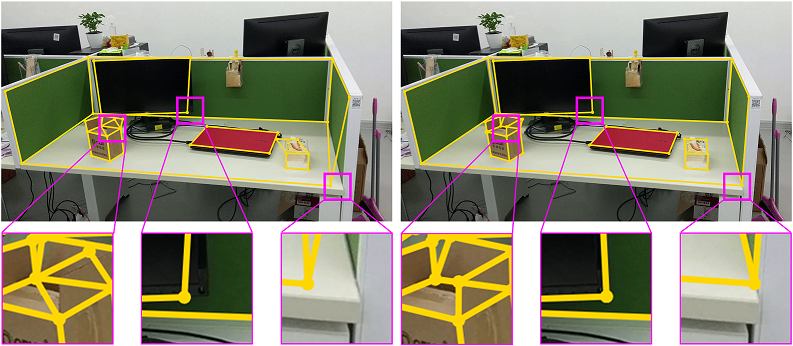 Figure 4
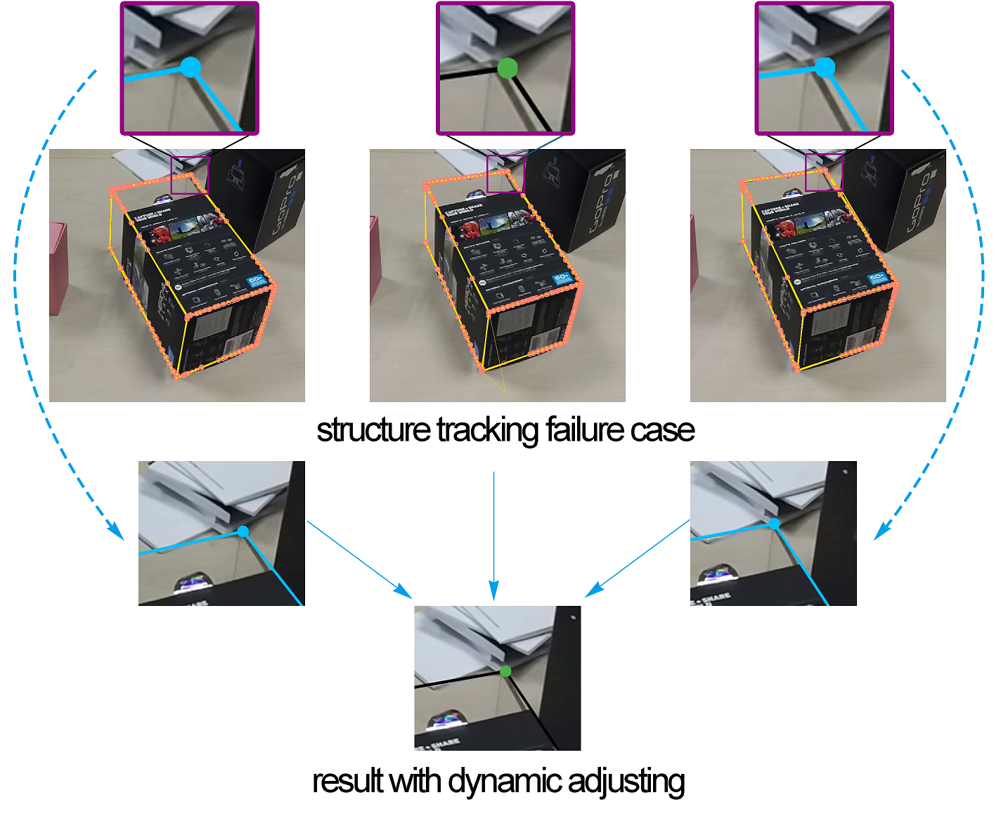 Figure 5
 Figure 6
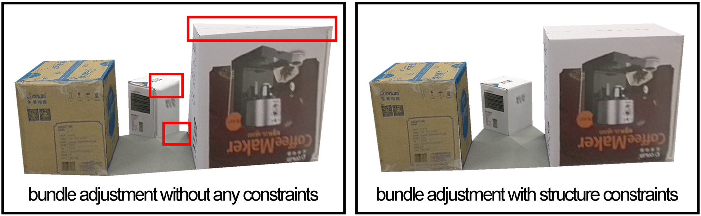 Figure 7
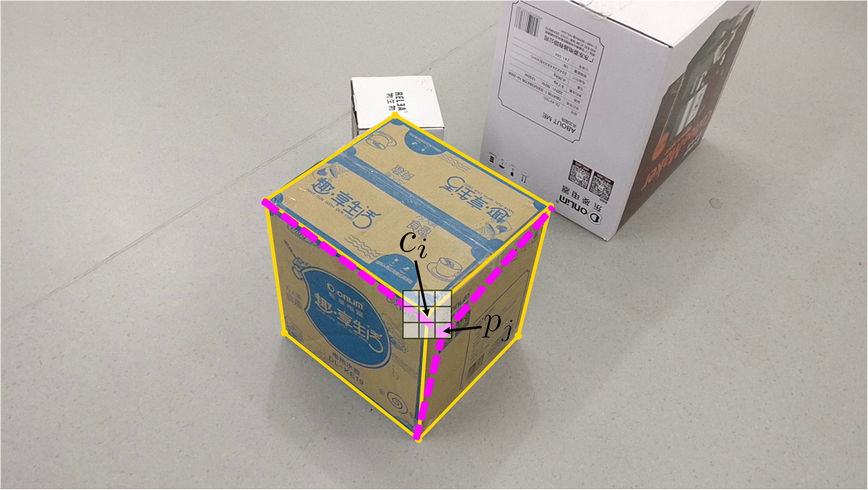 Figure 8
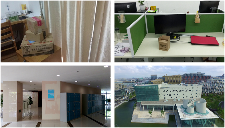 Figure 9
| frames | planes | points (adj.) | time(s) | |
|---|---|---|---|---|
| boxes | 300 | 11 | 23(70) | 380 |
| hall | 350 | 12 | 38(100) | 420 |
| toy house | 300 | 18 | 35(40) | 270 |
| desktop | 150 | 14 | 36(5) | 150 |
| library | 500 | 18 | 41(50) | 330 |
Peer Reviews
No public reviews on file for this paper yet. If you reviewed it on a platform where reviews are public (OpenReview, ICLR, NeurIPS, ICML), you can paste yours below so the community can read it here.
Videos
No videos yet. Explain this paper in a talk, walkthrough, or lecture? Add one.
Taxonomy
TopicsAdvanced Vision and Imaging · Robotics and Sensor-Based Localization · Optical measurement and interference techniques
Recovering 3D Planar Arrangements from Videos
Shuai Du
ShanghaiTech University
Youyi Zheng
ShanghaiTech University
Abstract
Acquiring 3D geometry of real world objects has various applications in 3D digitization, such as navigation and content generation in virtual environments. Image remains one of the most popular media for such visual tasks due to its simplicity of acquisition. Traditional image-based 3D reconstruction approaches heavily exploit point-to-point correspondence among multiple images to estimate camera motion and 3D geometry. Establishing point-to-point correspondence lies at the center of the 3D reconstruction pipeline, which however is easily prone to errors. In this paper, we propose an optimization framework which traces image points using a novel structure-guided dynamic tracking algorithm and estimates both the camera motion and a 3D structure model by enforcing a set of planar constraints. The key to our method is a structure model represented as a set of planes and their arrangements. Constraints derived from the structure model is used both in the correspondence establishment stage and the bundle adjustment stage in our reconstruction pipeline. Experiments show that our algorithm can effectively localize structure correspondence across dense image frames while faithfully reconstructing the camera motion and the underlying structured 3D model.
1 Introduction
As virtual reality device is becoming more and more popular, 3D content plays a key role associated with these devices. Instead of manually making 3D models using softwares such as 3Ds Max, Maya and Blender, automated 3D reconstruction methods are attracting more attentions due to its high efficiency. By now, a large body of research has been devoted in the field of 3D reconstruction in the aim of producing realistic 3D geometry [6, 7, 12, 22, 25]. However, most of these methods usually output low-level geometric point cloud. These low-level geometry information often lack structure and semantic properties of the 3D content, thus hinders direct usages of these data in the subsequent applications.
In recent, there emerges techniques which exploit high-level structure information such as Manhattan-world assumption [5], CSG representation [32], and repetitions [3] to help the process of 3D reconstruction. A common flavour of these approaches is that the structural information such as Manhattan-world assumptions and repetitions are ubiquitous in manmade scenes and thus can be exploited either at the early stage of analysis [3] or at the later stage of consolidation [5].
In this paper, we propose a semi-automatic method to recover the structured 3D model from video sequences. We focus on reconstruction of structured 3D models from videos captured with inexpensive consumer-level RGB cameras. We base our experiments on the speculation that the underlying structure of the 3D object is essentially hidden in the geometry and can be globally decoupled from the geometry [20]. This could not only give us a more stable bundle estimation but also a structured 3D model. Our key observation is that most manmade environments are constituted of many planar surfaces such as houses and indoor scenes, which inspires us to represent the structured 3D model as a set of planes and their arrangements (e.g., parallel planes and intersecting planes). We devise an optimization framework which simultaneously recovers the plane arrangements and the camera motion as well as the intrinsic relations among the planes.
Start with a video sequence of a 3D model captured with a hand-held consumer camera or downloaded from the internet, we let the user initiate a few planes in one single frame by specifying a sequence of points using mouse clicking (Figure 3). We detect planar regions and represent planes in the form of open or closed polygons depending on the point visibility. Our automatic tracking algorithm is then employed to track each polygon point in the rest frames. The tracking consists of a structure-based optical flow process and a backtracking process via dynamic programming. We then use the triangulation algorithm to calculate the motion of the camera and finally, we use a structure-constrained bundle adjustment algorithm to optimize the plane points by taking into consideration of the inter-relations of the planes.
We test our algorithm on various manmade scene data. By manually providing a sparse set of input (points) in the initial frame, we are able to track the structured points in dense image frames using our tracking algorithm. After the tracking procedure, our method automatically extracts structural relations among planes and uses the arrangement relations as constraints in the bundle adjustment. Constraints that fail to be detected by our algorithm can be further added by the user to provide additional cues to help reconstruct the 3D object. Finally, our algorithm can reconstruct an object satisfying all the constraints.
Our contribution contains two parts. The first part is a structure propagation method. After the user has initially marked out the structure model, we propagate the structure model using a dynamic tracking algorithm, which can relieve the user from marking too many things in order to establish correspondence across the frames. The second part is that we come up with a structure constrained bundle adjustment optimization process, wherein the structural constraints are gradually consolidated during optimization.
We organize this paper’s content as follows. Section discusses the related works in reconstruction and tracking areas. In Section and , we show the propagation step for dense correspondence matches, the reconstruct algorithm and our modified bundle adjustment method. Results are presented in Section 5. And we conclude with the discussion of our method in Section 6.
2 Related Work
A full review of current state-of-the-art 3D reconstruction algorithms is out of the scope of this paper. We refer interested readers to the excellent surveys on stereo vision [23] and multi-view geometry [9, 19]. Below we review the works that are closely related to ours on structure-based tracking and reconstruction.
Point tracking. To track the corresponding points between frames, Sam Hare et al. [8] combine matching and tracking together in a unified optimization formulation. They use their method to detect object and track under a large class of 3d pose or homography transformations. We tried a similar version of the method to track the plane corner points using homography warping, but due to the inherent noise in corner point detection which results in the subsequent Ransac computation of homography matrix unreliable, the tracking result shows to be impractical.
Another common way to track for corresponding points is to use optical flow. It is a dense field of displacement vectors which defines the translation of each pixel in a region. Popular techniques for computing dense optical flow include methods by Horn and Schunck [10], Lucas et al. [18], and Weinzaepfel et al. [29].
More recent research works include [28, 15, 2, 1]. Wedel et al. [28] explore fundamental matrix priors which favor flows that are aligned with epipolar lines. Lempitsky et al. [15] assume that a number of candidate flow fields have been generated by running standard algorithms possibly multiple times with a number of different parameters. Computing the flow is then posed as choosing which of the set of possible candidates is best at each pixel. And other methods like Brox et al. [2] and Bailer et al. [1] first do a coarse feature matching for large displacement optical flow to refine the result.
To the best of our knowledge, none of the above methods explicitly exploit a structure model to help the tracking process. Our approach utilizes the underlying planar structure to alleviate the instabilities in single point tracking and thus enables a more reliable frame-to-frame tracking.
Structure-based reconstruction. Many structure-based modeling approaches assume there is a structure. These structures include Manhattan-world assumption [5], cuboid assumption [13], CSG representation [32], symmetry [17, 35, 14] and repetitions [3], etc., which are exploited to help regulate and reconstruct the 3D object and to truly interpret the scene.
By giving pre-known constraints in perspective projection, we can recover the 3D information from a single image [36, 14, 26] by calculating the normals. But single image has a very limited field of view, and can not deal with the occlusion without additional symmetry assumption [14, 35].
Mura et el. [21] use clustered 3D range scans to create the structured 3D models of typical interior environments, namely of recognizing their structure of individual rooms and corridors.
By learning the unique features of different types of surfaces and the contextual relationships between them, Xiong et al. [33] propose a method to automatically convert the 3D point data from a laser scanner into a compact, semantically rich information model. And from panorama RGBD images, Furukawa et al. [11] use a graph to represent the internal structures and reconstruct an indoor scene as a structured model.
Relying on raw outputs of traditional multi-view stereo techniques, a structured model can be created and regularized with structural constraints discovered from the point cloud [34, 27]. Such methods could fail once the multi-view stereo methods return degenerated output due to occlusion, reflectance, and bad illuminations, etc.
In contrast, our method couples the process of structure discovering and structure regularization and jointly optimize the plane geometry and plane arrangements, at the cost of a light-weighted initial input of polygon points.
3 The approach
We now detail our algorithm. The main pipeline is devised into two key stages: a structure-based point tracking stage to establish point correspondence across frames and a joint optimization stage where camera motion and planar structures are recovered simultaneously.
3.1 Initialization of the structure model
The input to our algorithm is a video sequence of a 3D model or 3D scene captured by hand-hold cameras or downloaded from the internet. As mentioned before, our goal is to reconstruct the structured 3D model in terms of a set of planes and their arrangements. We represent each plane by a planar polygon.
During initialization, we allow the user to create these polygons manually since automatic detection of planar regions in images is an ill-posed problem and can be easily corrupted by occlusions in cluttered scenes. To create a planar face, the user simply clicks on the image to indicate a corner point of a planar face and then s/he moves the mouse to place the next corner point. Two corner points form a line segment of a planar face. On mouse move, the user sees a highlighted line segment connecting the previous point to the current mouse position (Figure 3). In such setting, the user can position the points more precisely by aligning the line segment with image edges. The user continues the task with existing corner points to create additional points and line segments of planar faces. Newly created line segments share vertices with existing line segments. This process leads to a graph with points as graph nodes and line segments as graph edges, for which we use the automatic planar region detection algorithm [17] to extract planar faces. Figure 3 left shows a snapshot of the interaction process. Since the polygon points are all marked by users, they may be inaccurate. However, this does not affect our point tracking algorithm as our structure-based tracking iteratively improves the points position based on detected structures by minimizing a structure error. This also helps ease users’ work in marking the structures at initialization.
Once the user draws up points and lines to form the structured model that needs to be reconstructed, our system automatically tracks these face points using a structured-guided dynamic tracking algorithm. The user can add additional points if they do not appear in the initial frame due to occlusions (yellow points and edges in Figure 2), our system then automatically tracks the newly added points in the subsequent frames. Occasionally, the user can help the tracking procedure by adjusting the result of some tracking points once occlusion happens or the edges get blurred, and the system will update the intermediate tracking results using dynamic programming. Finally, we will get all the corresponding points to feed into a structure constrained bundle adjustment algorithm.
3.2 Structure-guided Point Tracking
To trace the corner points of all planar faces in the marked image, a straightforward way is to employ optical flow [18, 29]. Unfortunately, a direct tracking with optical flow returns very bad results as it is based on local gradients without paying any attention to the global structure. See Figure 4 for an illustration of results from a direct tracing using optical flow.
We resort to an algorithm that exploits the structure information provided in the initial frame. Instead of directly tracing the points in a local window using optical flow, we make the following key observation: a corner point is an intersecting point of its two or more adjacent line segments in the polygonal faces. While tracking of a single point might lead to undesired positions, tracking of a line segment (a set of points) could be more reliable. To this end, we uniformly sample the points along each of the line segments which intersect at a corner point of the planar faces and track the sampled points from the first frame to the next by optical flow. For each line segment where is the -th sampled point on , each sampled point will have a new position , we weight the points with a propagation confidence value computed from the optical flow. We then run a weighted RANSAC algorithm to find the best fitting line associated with the new point positions. Intersection points are updated accordingly which completes the process of corner points tracking. In cases of more than two line intersections, we find the intersection point by weighted least squares. Figure 4 shows an example of the tracing process. Compared to single-point local tracing, our method generates much more reliable results.
Sometimes the result of structured optical flow shifts from the real position, this can be caused by a fuzzy point marked by the user. To relieve this problem, we create a local window for each tracking point. We consider each pixel as a candidate point, and we trace all pixels using the structure-guided propagation. In specific, each point in the local window is connected to the neighboring corner points of . This creates new line segments (see an illustration in Figure 5). We then trace these line segments for point using our structure-guided propagation. We choose the most confident traced point (measured as summed weights returned from the optical flow) as the new location for the tracking point of . See figure 5 for an illustration of the process. Each blue line is a candidate edge in the next frame.
Occasionally, the tracing could still fail if occlusion happens or the object edge blends with the background colors as the camera view changes as shown in Figure 6. We design a back tracing algorithm to address this issue. Once the tracking is failed in one frame, errors will accumulate in all subsequent frames and it is not invertible since we are not aware of at which frame the tracking goes down. Hence, we leave this to the user. If at any stage the user observes that point tracking goes wrong, s/he could simply adjust the point position by reposition of the corner points using mouse dragging. We devise a dynamic programming to automatically adjust the point positions in all the intermediate frames, detailed below.
Given the start point and the end point in two frames and , we would like to find a best path connecting these two points and going through points in the intermediate image frames. To increase the possibility of finding the optimal path, as previous, we start from a corner point (pixel) in frame and create a local window centered at that point. For each point in the window we trace its path along the subsequent frames using the same strategy as mentioned above (i.e., by tracing the line segments). Then each point in window at frame will be traced to a point in frame . In frame , we then create for each traced point a local window and repeat the process to frame until we reach frame .
Note that the above process creates a discrete set of local windows across all frames between and , thus guarantees the existence of a valid tracing path. However, such strategy quickly leads to exponential complexity as the size of local windows grows exponentially. To enable efficiency, we need to bound the search locally such that the windows size does not grow too quickly.
We devise a constrained window growing algorithm. We observe that the search region should be small when the frame is close to frame and becomes larger when it is far away from frame . This is not surprising due to the nature of camera motion in consecutive frames. Hence, for each intermediate frame , we restrict local window size to be . The center of local window at a frame (except for frame and ) is determined as the weighted center of all traced points from frame (weights are computed from optical flow). Note that this will crop out some traced points that are far away from the center. Figure 7 shows the tracing windows and it can be noted that the positions of window centers vary across frames.
We then establish links across all intermediate frames. Each pixel in the local window at frame is connected to all pixels in the local windows of frame and frame by creating edges. The weight of each edge is the key to our path finding algorithm. We relate it to the results of structure tracking. Let a point denote as the point to trace from frame and its traced points as in the next frame. Then the lowest weight is assigned to the link and the weight spreads to the neighbor of in an increasing manner when connecting to all points in the local window of frame , that is, the further it spread, the larger the weight becomes. We used as our weight function, where is a score returned from the optical flow algorithm. The best tracing path is found as the shortest path connecting points in frame to frame using dynamic programming.
4 Reconstruction and Modified Bundle Adjustment
After tracking, we get the whole sequence of images with corresponding points in them. Following the traditional structure from motion pipeline could give us a set of 3D points as well as the rigid camera transformations. However, this will completely ignore all the planar structures of the model, for example, points of planar faces might not lie on the same plane anymore. Hence, we integrate such constraints in our bundle adjustment algorithm. Besides that, additional structure relations such as coplanarity and orthogonality should be added as well. Detecting such relations from pure 2d images is an ill-posed problem due to the lack of 3D information. We thus resort to an iterative optimization approach to analyze such relations from 3D and then re-feed them into the bundle adjustment.
4.1 Image Formation and Camera Motion
For the completeness of exposition, we would like to briefly include some basic notions about the camera model we use and a basic description of the structure from motion pipeline. Interested readers are referred to read more sophisticated contents in the excellent book of [9].
Assume the camera coordinate of frame [math] is the world coordinate and the camera coordinate at frame is . Given any 3-D point in the world coordinate, we have where and are the local coordinates of in and respectively (assume and share the same origin, otherwise there will be a translation ). So we have , where is a rotation matrix. In general, the coordinates of a 3-D point according to two arbitrary coordinate bases have the following relation:
[TABLE]
where is the translation between the two corresponding coordinate bases.
We know an image is captured through a camera lens. When the aperture is small, the camera model can be regarded as a pinhole camera. In this case, the point x = on the image is given by the following equations:
[TABLE]
Here is the distance between CCD and aperture, is the 3D corresponding point of the 2d image. It can be easily derived from similarity geometry.
Usually, the image has at its up-left corner. It demands a shift in both and axis when assuming the focal point lies at image center. Combining all these together, we can get the relation between camera’s image plane and world’s 3D coordinate:
[TABLE]
where and are now homogeneous coordinates, K=\left[\begin{array}[]{cccc}f&0&u\\ 0&f&v\\ 0&0&1\\ \end{array}\right] is the intrinsic parameter of the camera, and represent the camera motion related to the world coordinate, and is the 3D position under the world coordinate system.
4.2 Sfm and Optimization
The relation between two corresponding points and in two images can be derived from equation 3:
[TABLE]
Each pair of R, T can be derived from the eight-point algorithm [9, 19]. After that, we can get relative , after the eight-point algorithm. We need to merge all relative , to a world coordinate. Let’s say, the relation between the and cameras is , the relation between the and cameras is . We can easily derive that the relation between the and cameras is .
Finally, we run the optimize process to reduce the error. We consider both the re-projection error and the structure error during the optimization. In detail, the re-projection error is formed as:
[TABLE]
where is the 2d image point of 3D in image .
Besides the re-projection error, we add an additional term to measure the structure error, which is the points on a same planar face should stay coplanar in 3D. This leads to the constraint:
[TABLE]
where is an edge on plane , is the normal direction of plane which can be computed from the edges. Optimizing the above equations leads us to a bundle adjustment of camera motion and structured planar faces. Still, there are other structure relations missing, such as coplanarity between two planar faces and orthogonality between two planar faces.
A direct analysis of such relations from 2d is not feasible, thus we detect the coplanarity and orthogonality in the estimated 3D from the above bundle adjustment. We employ a method similar to the method of GlobFit [16]. We detect near orthogonal, coplanar, and parallel plane groups and attempt to enforce them to be orthogonal, coplanar, and parallel. A group of planar faces are detected to be parallel if their normals coincide (. A group of planar faces are detected to be coplanar if their normals coincide and the line connecting their centers is close to orthogonal to their normals. Two parallel groups of planar faces are detected to be orthogonal if the angle between their normals is close to . To reduce the ambiguities in detecting these constraints, we first detect parallel groups of planes and take their weighted normal for the subsequent analysis of orthogonality and coplanarity. To detect parallel groups, we apply mean shift [4] on plane normals with a default bandwidth set to . During the optimization, if any of the group enforcement leads to an increase of error in the bundle adjustment, we release such group constraint. If the automatic detection fails, we let the user to indicate planar relations by clicking on relevant faces. The constraints of orthogonality, parallelism, and coplanarity are in the following forms:
[TABLE]
Here -s are edges connecting points in the two planes. We use Levenberg-Marquardt Algorithm to optimize the sparse camera motion.
5 Experiments
In this section, we experiment using real data to fully evaluate our algorithm. Figure 9 shows the example 3D models and scenes we use in our experiments. They include stacking boxes in a dorm, desktop workspace in a computer lab, corridor inside a building, a toy house, and a school library. They are captured either by a cell phone or by a UAV (the library scene). These models span a typical set of objects in manmade environments and many of them consist of a lot of planar structures which fit perfectly to our algorithm.
When it comes to real data, things get a little different. The first thing is that the camera’s intrinsic parameters are unknown. We solve this by assuming only the focal length of the camera is missing, and we try different values to unproject the 2d image and choose the one with the least error. The second is that real data always has blur due to the camera’s unstable moving and the resolution limitation, which has negative effects on our tracking process, even if the tracking is helped by users. So providing structure constraints will help to improve the optimization result.
Figure 10 shows the reconstruction results and Table 1 shows the statistics of the generated results. We render the reconstructed results using both shaded 3D model and textured model for clear illustration. To texture a planar face, we use a similar technology as in [24]. Our method allows the user to manually adjust the dynamic tracking process once failures were detected (see the point adjustment statistics in Table 1). We observe that such cases happen typically at places where occlusion happens (e.g., the occluded points in the toy house model) or when the structure lines to track blends with the background (Figure 6 and Figure 9 bottom left). We believe these two cases are inherently challenging to handle even with our human perception. We leave it as future work.
Time complexity. Our algorithm consists of a tracking part and a bundle optimization part. The tracking employed a shortest path dynamic programming whose time complexity is with the largest window size and the number of frames (note that here our graph is layered,thus the complexity is different from a traditional all-pairs shortest path algorithm on a graph which is known to have an approximate complexity of . The bundle adjustment optimization runs at the same rate as traditional Sfm methods which is super fast in our case, as our input is a sparse set of plane points. It takes less than 1 minute to optimize the toy house model on a laptop with 3.2GHz CPU and 8GB RAM.
Comparison. We conducted a pilot comparison with two state-of-the-art 3D reconstruction methods which we consider to be relevant. The first one is the planar reconstruction method proposed by Li et al. [17] and the other is the famous structure from motion software VisualSFM proposed by Wu et al. [30, 31]. Figure 11 shows their results. Without any structural constraints, the VisualSFm system merely generated a set of incomplete point cloud while the loose symmetry and coplanar constraints used in the method of [17] still cannot guarantee a convergence of the output to a desired one especially when only dealing with a single image (see the drifted faces). Our method faithfully recovers all planar faces and their inter-relations.
Limitation. By now, our method requires the user to specify an initial set of corner points and edges which constitute the planar faces. The initial specification typically takes around 2-5 minutes. This is the main limitation of our algorithm. By far, we are not aware of any automatic algorithms that can robustly identify planar regions from RGB images. An intriguing direction to explore is to use some deep-learning based approaches for detecting planar regions. Another limitation is that our structure-based dynamic tracking could fail at places where the edges get weak or occlusion happens. This is unavoidable due to the inherent noise and motion blur during video capture. A pre-denoise or deblurring process could alleviate the problem a bit but completely solving such problems requires more significant efforts as this needs a semantic understanding of the underlying scene.
6 Conclusion
In conclusion, this paper provides a semi-automatic 3D reconstruction algorithm that recovers a set of structured planes along with their arrangements from a video. Our key contribution is a structure model represented as a set of planes whose arrangements form a faithful description of the scene model. We propose a dynamic point tracking algorithm which explicitly exploits the structure lines as effective means for identifying reliable corner point locations. Besides, a structure-augmented optimization framework with bundle adjustment is introduced to jointly optimize the plane arrangements and the plane geometry. Our future work will consider to combine the traditional Sfm process with automatic structure analysis to enable a fully automated 3D reconstruction pipeline, which we believe will open up new possibilities in the area of structure-based 3D reconstruction and bring potential influence to the community.
The reference list from the paper itself. Each links out to its DOI / PubMed record.
- 1[1] C. Bailer, B. Taetz, and D. Stricker. Flow fields: Dense correspondence fields for highly accurate large displacement optical flow estimation. In Proceedings of the IEEE International Conference on Computer Vision , pages 4015–4023, 2015.
- 2[2] T. Brox and J. Malik. Large displacement optical flow: descriptor matching in variational motion estimation. IEEE transactions on pattern analysis and machine intelligence , 33(3):500–513, 2011.
- 3[3] D. Ceylan, N. J. Mitra, Y. Zheng, and M. Pauly. Coupled structure-from-motion and 3d symmetry detection for urban facades. ACM Trans. Graph. , 33(1):2:1–2:15, 2014.
- 4[4] Y. Cheng. Mean shift, mode seeking, and clustering. IEEE transactions on pattern analysis and machine intelligence , 17(8):790–799, 1995.
- 5[5] Y. Furukawa, B. Curless, S. M. Seitz, and R. Szeliski. Manhattan-world stereo. In Computer Vision and Pattern Recognition, 2009. CVPR 2009. IEEE Conference on , pages 1422–1429. IEEE, 2009.
- 6[6] Y. Furukawa, B. Curless, S. M. Seitz, and R. Szeliski. Towards internet-scale multi-view stereo. In Computer Vision and Pattern Recognition (CVPR), 2010 IEEE Conference on , pages 1434–1441. IEEE, 2010.
- 7[7] Y. Furukawa and J. Ponce. Accurate, dense, and robust multiview stereopsis. IEEE transactions on pattern analysis and machine intelligence , 32(8):1362–1376, 2010.
- 8[8] S. Hare, A. Saffari, and P. H. Torr. Efficient online structured output learning for keypoint-based object tracking. In Computer Vision and Pattern Recognition (CVPR), 2012 IEEE Conference on , pages 1894–1901. IEEE, 2012.