Capacity Region of Layered Erasure One-sided Interference Channels without CSIT
Yan Zhu, Dongning Guo

TL;DR
This paper determines the exact capacity region of a layered erasure one-sided interference channel with receiver-only CSI, extending previous special cases and applicable to arbitrary fading statistics.
Contribution
It provides a complete characterization of the capacity region for layered erasure one-sided interference channels without CSIT, generalizing prior results.
Findings
Capacity region is fully characterized.
Results hold for arbitrary fading statistics.
Generalizes previous special case results.
Abstract
This paper studies a layered erasure interference channel model, which is a simplification of the Gaussian interference channel with fading using the deterministic model approach. In particular, the capacity region of the layered erasure one-sided interference channel is completely determined, assuming that the channel state information (CSI) is known to the receivers, but there is no CSI at transmitters (CSIT). The result holds for arbitrary fading statistics. Previous results of Aggarwal, Sankar, Calderbank and Poor on the capacity region or sum capacity under several interference configurations are shown to be special cases of the capacity region shown in this paper.
Click any figure to enlarge with its caption.
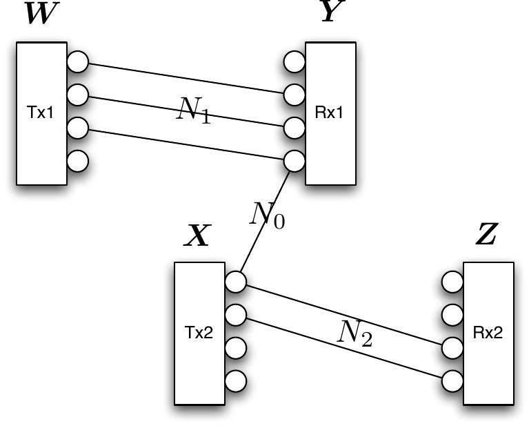 Figure 1
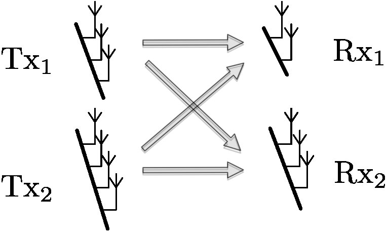 Figure 2
Peer Reviews
No public reviews on file for this paper yet. If you reviewed it on a platform where reviews are public (OpenReview, ICLR, NeurIPS, ICML), you can paste yours below so the community can read it here.
Videos
No videos yet. Explain this paper in a talk, walkthrough, or lecture? Add one.
Taxonomy
TopicsAdvanced MIMO Systems Optimization · Cooperative Communication and Network Coding · Wireless Communication Security Techniques
{tikzpicture}
[scale=.6] \coordinate(origin) at (0, 0); \draw[-¿, ultra thick] (0,0) – (6,0) node[below] ; \draw[-¿, ultra thick] (0,0) – (0, 8.5) node[left] ; \coordinate(C1) at (4,0); \coordinate(C11) at (4,10); \coordinate(C2) at (0,6); \coordinate(C22) at (10,6); \coordinate(L1x) at (4.5,0); \coordinate(L1y) at (0,13.5); \coordinate(L2x) at (5,0); \coordinate(L2y) at (0,10); \coordinate(L3x) at (5.8,0); \coordinate(L3y) at (0,8.7); \coordinate(L4x) at (8,0); \coordinate(L4y) at (0,8); \coordinate(L0) at (intersection of C1–C11 and L1x–L1y); \coordinate(L1) at (intersection of L1x–L1y and L2x–L2y); \coordinate(L2) at (intersection of L2x–L2y and L3x–L3y); \coordinate(L3) at (intersection of L3x–L3y and L4x–L4y); \draw[very thick] (C1) node [below]–(L0); \draw[very thick] (L0) –node[right] (L1); \draw[very thick] (L1)node[right] –node[right] (L2)node[right]; \coordinate(up) at (intersection of C2–C22 and L2–L3); \draw[very thick] (C2) node[left]–(up); \draw[very thick] (up)–(L2); \draw[very thick] (L3)node[right] –node[right] (L4y); \draw[very thick] (L3) – node[right](L2); [black] (C1) circle (1mm); [black] (C2) circle (1mm); \node[rectangle, inner sep=1mm,draw=blue, fill=blue] at (L0) ; \node[rectangle, inner sep=1mm,draw=blue, fill=blue] at (up) ; \node[star, inner sep=.6mm,draw=red, fill=red] at (L1) ; \node[star, inner sep=.6mm,draw=red, fill=red] at (L2) ; \node[star, inner sep=.6mm,draw=red, fill=red] at (L3) ; \draw[dashed] (L0) –( L0 -— C2) node[left];