Spin-wave interference in three-dimensional rolled-up ferromagnetic microtubes
Felix Balhorn, Sebastian Mansfeld, Andreas Krohn, Jesco Topp, Wolfgang, Hansen, Detlef Heitmann, and Stefan Mendach

TL;DR
This study explores how spin waves behave in three-dimensional rolled-up ferromagnetic microtubes, revealing quantized modes influenced by the tube's geometry, which could impact future magnonic device design.
Contribution
It demonstrates the quantization of spin-wave modes in 3D microtubes and shows how their spectrum can be engineered by adjusting physical parameters.
Findings
Identification of quantized azimuthal spin-wave modes
Mode spectrum tunable by tube radius and layer number
Confirmation of spin-wave resonator behavior in microtubes
Abstract
We have investigated spin-wave excitations in rolled-up Permalloy microtubes using microwave absorption spectroscopy. We find a series of quantized azimuthal modes which arise from the constructive interference of Damon-Eshbach type spin waves propagating around the circumference of the microtubes, forming a spin-wave resonator. The mode spectrum can be tailored by the tube's radius and number of rolled-up layers.
Click any figure to enlarge with its caption.
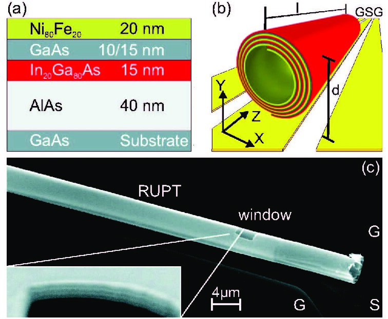 Figure 1
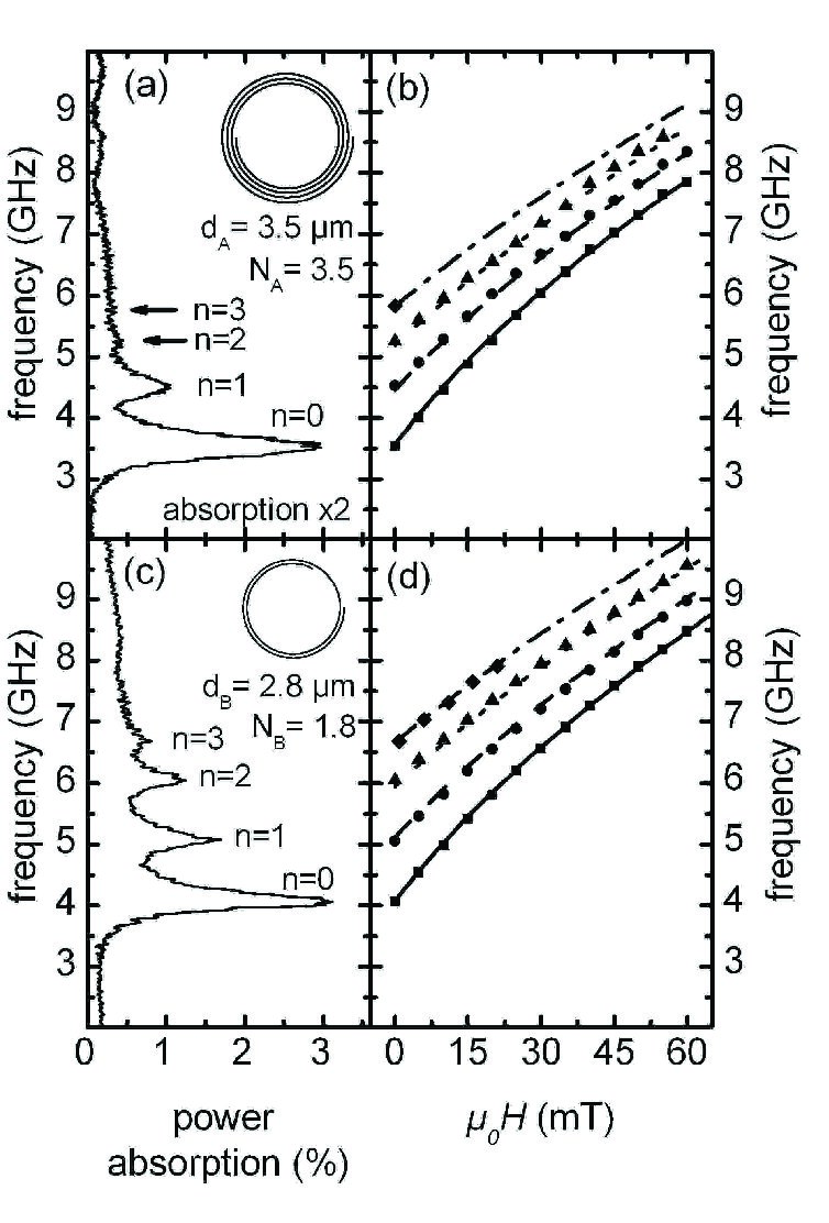 Figure 2
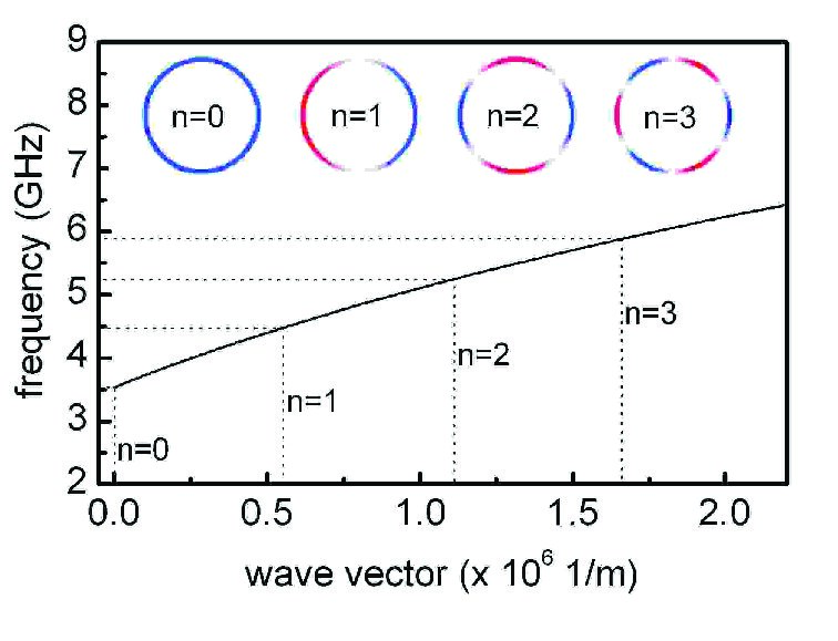 Figure 3
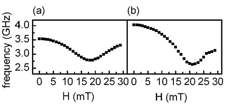 Figure 4
Peer Reviews
No public reviews on file for this paper yet. If you reviewed it on a platform where reviews are public (OpenReview, ICLR, NeurIPS, ICML), you can paste yours below so the community can read it here.
Videos
No videos yet. Explain this paper in a talk, walkthrough, or lecture? Add one.
corresponding author, email: ][email protected]
Spin-wave interference in three-dimensional rolled-up ferromagnetic microtubes
Felix Balhorn
Sebastian Mansfeld
Andreas Krohn
Jesco Topp
Wolfgang Hansen
Detlef Heitmann
Stefan Mendach
[
Institut für Angewandte Physik und Zentrum für Mikrostrukturforschung, Universität Hamburg, Jungiusstrasse 11, D-20355 Hamburg, Germany
Abstract
We have investigated spin-wave excitations in rolled-up Permalloy microtubes using microwave absorption spectroscopy. We find a series of quantized azimuthal modes which arise from the constructive interference of Damon-Eshbach type spin waves propagating around the circumference of the microtubes, forming a spin-wave resonator. The mode spectrum can be tailored by the tube’s radius and number of rolled-up layers.
Spin-wave excitations in thin films and patterned ferromagnetic structures are of both fundamental and practical scientific interest. On the micrometer scale geometric boundaries induce quantization conditions on spin-wave excitations. This effect has been shown for flat laterally patterned geometries such as wires and rectangular elements Jorzick et al. (2002); Bayer et al. (2004); Demidov et al. (2008) as well as for micrometer sized rings and discs Jorzick et al. (1999); Park and Crowell (2005); Giesen et al. (2007); Podbielski et al. (2006); Neudecker et al. (2006).
In this letter we report on the fabrication and experimental investigation of novel three-dimensional ferromagnetic microstructures consisting of rolled-up Permalloy/semiconductor () layers, in the following termed rolled-up Permalloy microtube (RUPT). Using microwave absorption spectroscopy on homogenously magnetized RUPTs we observe a series of sharp modes which arise from the constructive interference of Damon-Eshbach type Damon and Eshbach (1961) spin waves traveling along the circumference of the RUPT. These interference conditions are quite universal. They resemble the acoustic whispering-gallery modes in the St. Pauls Cathedral, originally explored by Lord Rayleigh Rayleigh (1912), optical resonators based on semiconductor microtubes Strelow et al. (2008); Mendach et al. (2008) and microdiscs McCall et al. (1992); Peter et al. (2005) or dielectric microspheres Vernooy et al. (1998); Vahala (2003).
The measurements discussed in this work were performed on two RUPTs with different radii , winding numbers (giving the number of revolutions of the rolled-up material) and layer composition (RUPT A and RUPT B, parameters given below). They were prepared from a strained Permalloy/semiconductor multilayer, utilizing the self-rolling effect Cho (2006) pioneered by Prinz et al. Prinz et al. (2000) and Schmidt et al. Schmidt and Eberl (2001).
For RUPT A (RUPT B) a nm thick Permalloy layer was thermally evaporated on a molecular beam epitaxy grown heterostructure made of nm ( nm) GaAs, nm and nm AlAs on a GaAs substrate (see Fig. 1(a)). The lattice constant of InAs is significantly larger than for GaAs and allows a pseudomorphically strained growth. By selectively etching the AlAs sacrificial layer the layer system is released from the substrate and minimizes its strain energy by rolling up into a tube (see Fig. 1(b) and (c)). The diameter of the RUPT is determined by the composition and thickness of the layer system Grundmann (2003). The length and winding number of the RUPT can be precisely controlled by photolithography, i.e. by defining the lateral dimensions of a strained mesa which is rolled-up in the final selective etching step from a well-defined starting edge Schumacher et al. (2005). After the measurements were performed on RUPT A, a window was prepared into its surface by focused ion beams to enable an analysis of its inner structure (see inset in Fig. 1(c)). The RUPT is tightly rolled up, spiral in shape and formed from windings of the multilayer. Together with each RUPT an unpatterned Permalloy film from the same wafer was prepared, using the same thermal evaporation step to allow the determination of reference parameters. The film for RUPT A (RUPT B) has a saturation magnetization mT ( mT) and a Gilbert damping constant (), as determined by microwave absorption measurements.
We investigated the spin-wave spectrum using high-resolution microwave absorption spectroscopy. For this purpose the RUPT was removed from the GaAs substrate and placed on the m wide signal line of a coplanar waveguide (CPW) using a setup with piezo controlled manipulation needles Mendach et al. (2008). The CPW was defined by optical lithography on a GaAs wafer and consists of a nm thick trilayer of Cr/Ag/Au. A static external magnetic field was applied in the plane of the waveguide along the tube’s axis. With a vector network analyzer (VNA) we measured the microwave transmission through the CPW in dependence of the microwave frequency . The high-frequency magnetic field of the CPW pointed perpendicularly to the axis of the RUPT. The excitation of a spin wave is indicated by a reduced transmission of the waveguide due to the absorption of power at the corresponding excitation frequency . Each measurement was normalized to a reference measurement, taken with mT applied perpendicularly to the axis of the RUPT. To assure a well-defined magnetization configuration within the RUPT, it was magnetized along its axis with mT prior to every frequency sweep, ramped down to zero and then ramped up to the actual field. For a detailed description of the technique used in this experiment, see Ref. Giesen et al. (2007).
Let us first discuss measurements performed on RUPT A with diameter , length and rolling number . Figure 2(a) shows the excitation spectrum of RUPT A at an external magnetic field . Four distinct resonances are observed at GHz, GHz, GHz, and GHz. With increasing external magnetic field the spacing between all resonance peaks reduces until they overlap. To determine the exact eigenfrequency of each spin wave each peak was fitted assuming a Lorentzian shaped curve. Figure 2(b) depicts a plot of the resonance frequency of the three larger resonance peaks for different external magnetic fields . Figure 2(c) and (d) display corresponding data for RUPT B with diameter , length and winding number . This RUPT shows four resonance peaks for at GHz, GHz, GHz, and GHz. RUPT B absorbs about twice as much microwave power as RUPT A.
In the following we show that the resonances in the spectra of RUPT A and RUPT B are due to spin waves traveling around the RUPTs perimeter. They form resonant modes if the periodic boundary condition for a ring resonator
[TABLE]
is fulfilled. Here denotes the wavelength of the spin wave, the azimuthal wave vector and the diameter of the RUPT. Condition (1) is true if an integer number of wavelengths fits into the circumference of the RUPT, so that spin-waves interfere constructively. We prepared RUPT B on purpose with smaller diameter and a winding number of only to confirm our explanation. The fact that we observe four resonant modes for RUPT B as well confirms that they originate from interfering azimuthal spin waves and not from individual isolated modes in single films or parts of the circumference. In particular we observe that with decreasing diameter for RUPT B as compared to for RUPT A the resonance frequency increases as expected from the spin-wave model described below.
At first it seems surprising that spin waves interfere on the circumference, since the actual ferromagnetic film is of spiral and not closed shape. The explanation is that the individual overlapping films couple strongly through dipole-dipole interaction. This coupling also automatically leads to a renormalization of the spin-wave mode frequencies as compared to a single-layered film. This can be modeled by a single-layered tube with an effective thickness . Additionally, the curved shape of the microtubes also leads to both static and dynamic demagnetization effects Mendach et al. (2008). This, the demagnetization, coupling and renormalization and their incorporation into a spin-wave model will be addressed in detail in the following.
Spin-wave model. — To describe our data, we start from a model introduced by Kalinikos and Slavin Kalinikos and Slavin (1986) for a flat, thin film, modified by Guslienko et al. Guslienko et al. (2003). Here, the resonance frequency is given by
[TABLE]
is the internal magnetic field, is the exchange constant for Permalloy (), is the saturation magnetization and is the dipole-dipole interaction matrix given by
[TABLE]
with
[TABLE]
Spin waves traveling around the perimeter of an axially magnetized RUPT with an external magnetic field parallel to its axis exhibit Damon-Eshbach character for all field values. The dispersion of these spin waves calculated with equation (2) is shown in Fig. 3. From the quantized wave vector given by equation (1) we directly get the corresponding resonance frequency. We see that indeed the spacing between the modes decreases with mode number as observed in the experiment. We used this model to fit our data. The coupling and frequency renormalization were accounted for by an effective layer thickness . As explained below, the demagnetization was considered by adding an effective demagnetizing field to the internal magnetic field, . We find a nearly perfect agreement with the experimental data using nm and mT for RUPT A and nm and mT for RUPT B. The fit is shown in Fig. 2(a) and (b).
Demagnetization. — Due to the bent shape of the RUPT any precession of the magnetization leads to magnetization components pointing towards geometric boundaries. This causes dynamic demagnetizing effects which form a two-dimensional potential energy landscape for a precessing spin Mendach et al. (2008). For this reason, even for the RUPT has a resonance frequency . Thus, to explain our data we have to take into account an additional effective demagnetizing field . This concept is similar to the treatment of a thin ferromagnetic wire in the Kittel formula Kittel (1948). For wires such an effective field can be accurately retrieved from the hard-axis dispersion relation, i.e. when external field and long axis of the wire are perpendicular to each other. In this case, if the external field is large enough, it forces the magnetization to align itself also perpendicularly. This creates a static demagnetization field, which reduces the internal field in the wire. At the external field for which the frequency of the fundamental spin-wave mode is minimal, the external and the demagnetization field compensate each other Bailleul et al. (2003). Using this value for the resonance frequency and dispersion of a thin wire can be modeled within sufficient accuracy. We used an identical approach for the RUPTs. The experimentally observed hard-axis dispersion indeed displays a pronounced minimum at mT for RUPT A and at mT for RUPT B (see Fig. 3(b) and (c)), which is quite close to the values used above to fit our data.
Dipole coupling. — The RUPT is of spiral shape so that at first sight there is no periodic azimuthal path through ferromagnetic material for the spin-waves to travel. Instead the spin-waves traveling in individual layers of the RUPT couple via dipole-dipole interaction. To support this approach, we performed micromagnetic simulations using the OOMMF framework Donahue and Porter (1999). The simulation of the bent shape of a microtube is, however, extremely time consuming and beyond our computer capacities due to the rectangular discretization of space required for the simulations with OOMMF. Instead, we simulated two thin rectangular Permalloy stripes stacked vertically (separation distance 35 nm). Only the lower stripe is excited directly by a ps long pulse applied perpendicular to an external in-plane field of mT. Our simulations show that the second, not directly excited stripe follows the excitation of the lower stripe via dipole-dipole coupling with almost the same amplitude, indeed indicating strong dipole-dipole coupling.
Renormalization. — Due to the coupling the spin excitations can be treated as an one-layered spin-wave system, described by an effective thickness. As discussed above, we find a nearly perfect agreement using an effective thickness of nm (30 nm) for RUPT A (B). These values lie in between the thickness of a single layer, nm, and the total thickness of nm ( nm) for RUPT A (B). Also in the micromagnetic simulations we find that the resonance frequency of the coupled two-layered stripe system is shifted to higher frequencies with regard to the single-layered system, which can indeed be described by an increased effective thickness.
The fits in Fig. 2 agree extremely well with the experimental data for RUPT A, while for RUPT B we find small deviations. We attribute this to the fact that one part of RUPT B consists of two layers, while the other one consists of only one layer. For this reason the difference between both parts is much larger than the difference between the parts of RUPT A with three and four layers, which perhaps is the reason why the effective thickness ansatz is less accurate here.
In conclusion, we have fabricated and investigated novel ferromagnetic microtube ring resonators. We observe quantized spin-wave modes arising from the constructive interference on the circumference of the tube. The mode spectrum can be tailored by the tube’s radius and number of windings. The confinement in these microtube ring resonators is, in contrast to flat ferromagnetic structures, not governed by geometrical edges and their complicated magnetization patterns and loss mechanisms. In this way our microtube ring resonators open a wide field of fundamental research and practical applications.
We would like to thank Markus Bröll, Stephan Schwaiger and Yuliya Stark for help during the tube preparation and Jan Podbielski and Dirk Grundler for fruitful discussions. We acknowledge financial support by the DFG via Grant Nos. SFB 668, SFB 508, and GrK 1286.
The reference list from the paper itself. Each links out to its DOI / PubMed record.
- 1(1)
- 2Jorzick et al. (2002) J. Jorzick, S. O. Demokritov, B. Hillebrands, M. Bailleul, C. Fermon, K. Y. Guslienko, A. N. Slavin, D. V. Berkov, and N. L. Gorn, Phys. Rev. Lett. 88 , 047204 (2002).
- 3Bayer et al. (2004) C. Bayer, J. P. Park, H. Wang, M. Yan, C. E. Campbell, and P. A. Crowell, Phys. Rev. B 69 , 134401 (2004).
- 4Demidov et al. (2008) V. E. Demidov, S. O. Demokritov, K. Rott, P. Krzysteczko, and G. Reiss, Phys. Rev. B 77 , 064406 (2008).
- 5Jorzick et al. (1999) J. Jorzick, S. O. Demokritov, B. Hillebrands, B. Bartenlian, C. Chappert, D. Decanini, F. Rousseaux, and E. Cambril, Appl. Phys. Lett. 75 , 3859 (1999).
- 6Park and Crowell (2005) J. P. Park and P. A. Crowell, Phys. Rev. Lett. 95 , 167201 (2005).
- 7Giesen et al. (2007) F. Giesen, J. Podbielski, and D. Grundler, Phys. Rev. B 76 , 014431 (2007).
- 8Podbielski et al. (2006) J. Podbielski, F. Giesen, and D. Grundler, Phys. Rev. Lett. 96 , 167207 (2006).